Interpack CE-12P User manual

Page 1 of 36
CE-12P
Automatic Case Erector
& Bottom Sealer
OPERATION MANUAL & PARTS LIST
This manual also available at www.itape.com.
Rapid Packaging, Inc.
763-404-8900 | [email protected]
www.RapidPackaging.com

Page 2 of 36
TABLE OF CONTENTS
GENERAL SAFETY RULES.................................................................................3
POWER SOURCE WIRING ..................................................................................3
CE-12P LAYOUT...................................................................................................4
MACHINE INSTALLATION ...................................................................................5
MANUAL FUNCTION LIST...................................................................................6
FAULT LIST...........................................................................................................6
OPERATION..........................................................................................................7
ABNORMAL REMEDY .......................................................................................10
ELECTRIC CIRCUIT ...........................................................................................12
AIR PRESSURE CIRCUIT ..................................................................................19
PNEUMATIC PART LIST ....................................................................................20
FRONT FLAP FOLDING ASSEMBLY ................................................................20
CASE DRAWING ASSEMBLY............................................................................21
LEFT & RIGHT FLAP FOLDING ASSEMBLY....................................................23
REAR FLAP FOLDING ASSEMBLY...................................................................24
SAFETY DOOR ASSEMBLY ..............................................................................26
HOPPER BASE...................................................................................................27
HOPPER TOP UNIT............................................................................................29
BOTTOM SEALING ASSEMBLY........................................................................31
TOP UNIT ADJUSTING ASSEMBLY..................................................................34
ELECTRIC CONTROL BOX ...............................................................................36

Page 3 of 36
GENERAL SAFETY RULES
1. Read and understand the entire instruction manual before operating the machine.
Know it’s limitations, as well as the specic potential hazards peculiar to it.
2. Make certain the machine is properly grounded.
3. Before operating the machine, remove ties, rings, watches other jewelry, and roll up
sleeves above the elbows. Remove all loose clothing and conne long hair. Do not
wear gloves.
4. Keep the oor around the machine clean.
5. Keep machine guards in place at all times when the machine is in use.
6. Do not overreach. Maintain a balanced stance at all times so that you do not fall or
lean against blades or other moving parts.
7. Make all machine adjustments or maintenance with the machine unplugged from the
power source.
8. Replace warning labels if they become obscured or removed.
9. Made sure the power source switch is in the OFF position before connecting the
machine to the power source
10.Make a habit of checking to see that the keys and adjusting wrenches are removed
before turning on the machine.
11. Keep belt guard and blade guards in place and in working order.
12.Failure to comply with all of these warnings could lead to serious injury.
POWER SOURCE WIRING
1. Before connecting, make sure the voltage is the same for both the machine and
the power source.The machine has been wired before shipment, and all electrical
information (such as voltage) indicated on the electrical instruction label.
2. Connect the power source wires to the “R.S.T.” connection points.The machine must
be properly grounded to prevent damage from electric shocks. (3 phase only)
3. After the power source wires have been connected, check to see if the wires are
connected to the correct points by the running direction of the left and right driving
belts. If the driving belts run in the correct direction, then the power source wires are
connected to the correct points. If the driving belts run in the opposite direction, cut
off the power source and change any two of the three power source wires to obtain
the correct running direction. (3 phase only)
Page 4 of 36
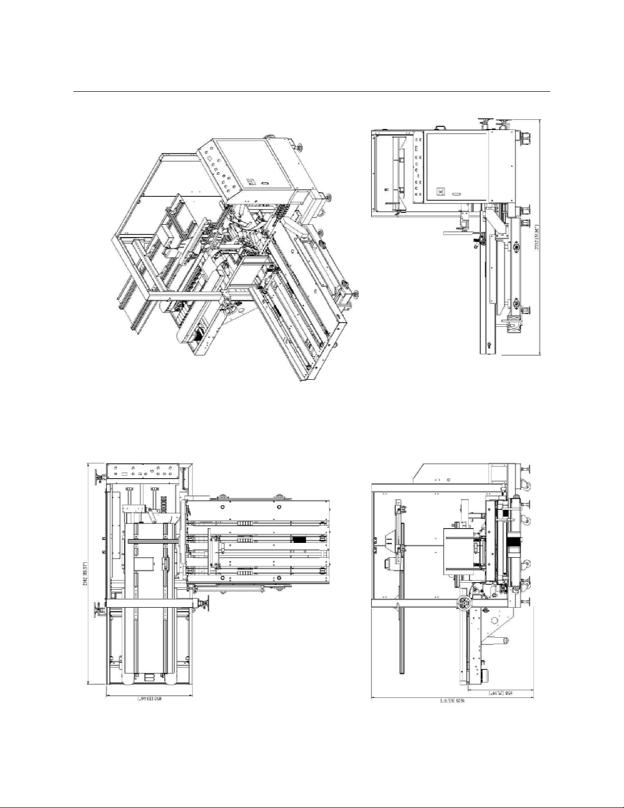
CE-12P LAYOUT

Page 5 of 36
MACHINE INSTALLATION
1. Please open the package and discharge the machine carefully for the installation.
Please check if appearance is food without any damage, otherwise, please advise
our company.
2. After installation, adjust the height of working table to parallel with the height of your
production line.
3. Remove the xed items inside the machine. (Ex: wooden block, plastic band)
4. Locate the machine, plus in the power source.
5. Connect pressure air source and adjust pressure to 5 kgs ~ 6kgs, then open manual
valve (VHS4000-03)
6. Machine testing: Switch on the Magnetic Breaker located inside the Control Box,
then press “Run Preparative”, turn Button (CS1) on Manual, start testing by Manual
Digital No. on Control Panel.
7. Side Belt On: Turn Manual No. to 01→press Manual On (Belt clockwise)→press
Manual Off (Belt stop).
a. Vacuum Activated: Turn Manual No. to 02→press Manual On (Vacuum cup suck
on)→press Manual Off (vacuum cup suck off)
b. Vacuum cup forward: Turn Manual No. to 03→press Manual On (Vacuum cup
forward)
c. Vacuum cup backward: Turn Manual No. to 04→press Manual On (Vacuum cup
forward)]
d. Guide Cylinder: Turn Manual No. to 05→press Manual On (Forming mechanism
effect) →press Manual Off (Forming mechanism return)
e. Front Minor Flap Forward Up: Turn Manual No. to 06→press Manual On (Front
Minor Folder upward up)
f. Rear Minor Flap Forward Up: Turn Manual No. to 07→press Manual On (Rear
minor ap forward up)
g. Left Major Flap Forward Up: Turn Manual No. to 08→press Manual On (Left
major ap forward up)
h. Right Major Flap Forward Up: Turn Manual No. to 09→press Manual On (Right
major ap forward up)
i. Vacuum release: Turn Manual No. to 10→press Manual On (Vacuum release)
j. Pushing Cylinder: Turn Manual No. to 11→press Manual On (Pushing cylinder
forward)

Page 6 of 36
MANUAL FUNCTION LIST
No. Description
01 Side Belt On
02 Vacuum Activated
03 Vacuum Cup Forward
04 Vacuum Cup Backward
05 Guide Cylinder
06 Front Minor Flap Folding Up
07 Rear Minor Flap Folding Up
08 Left Major Flap Folding Up
09 Right Major Flap Folding Up
10 Vacuum Released
11 Pushing Cylinder
FAULT LIST
No. Description
01 Low Air Pressure
02 Not in Initial Position
03 Vacuum Not Detected
04 Hopper Empty
05 Carton Withdraw Failure
06 Carton Jam
07 Tape Application Problem
08 Motor Problem
09 Safety Door Open
10 Emergency Stop Not Reset
11 Front Flap Folder Cylinder Not In Position
12 Rear Flap Folder Cylinder Not In Position
** When Alarm Sounds
1. Press “Alarm Reset” to stop alarm
2. Press and Hold Cycle Stop Button for 3 Seconds and Troubleshoot Fault
3. Press the button which is ashing to stop alarm and home-position
Page 7 of 36
OPERATION
1. Please make sure correct power source 110V, turn on Magnetic Breaker. Connect air
pressure at 5-6 kg/s.q.cm, switch on Manual Valve.
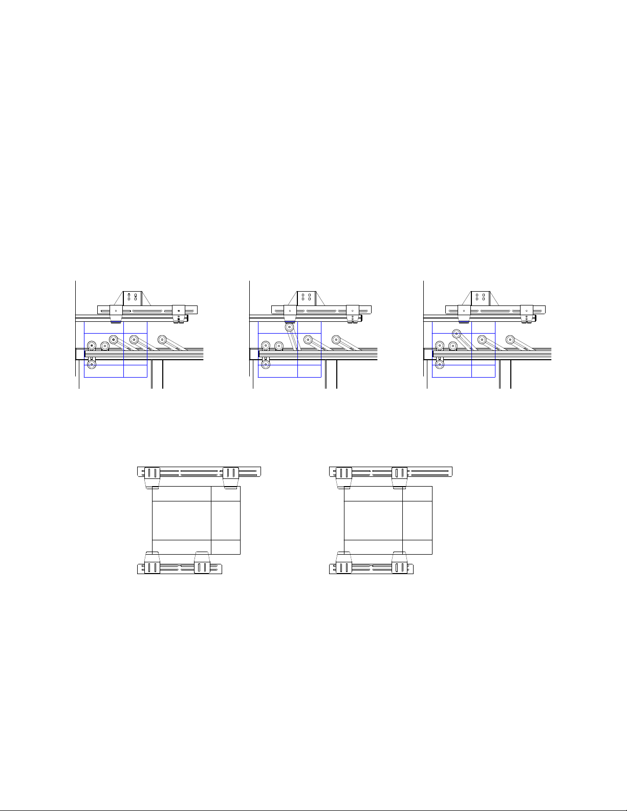
2. Adjust the location of Left//Right Belt (as Drawing 2) to t the wide of cartons (as
Drawing 1)
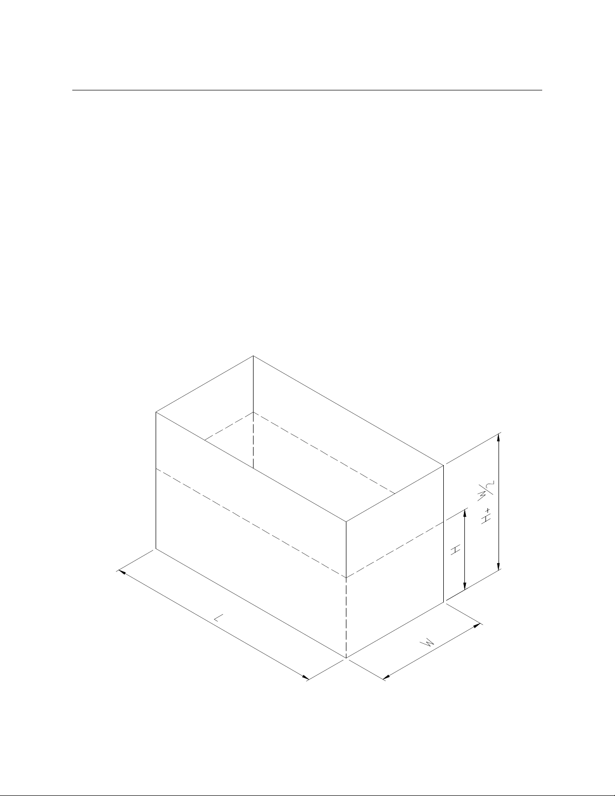
3. Adjust the location of Upper Working Table to t the height of carton plus half wide
(H+W/2). Notice: When the total is smaller than 300mm, adjust the location of
Sucking Plate rstly. Then adjust the location of Upper Working Table (as Drawing
2). Vacuum Cup can’t hit the stopper, Manual Valve of useless Vacuum Cup have to
be turn off.
4. Adjust the location of Magazine to the size of half wide (W/2).
5. Adjust the location of Carton Drawing Mechanism to the size of half wide (W/2).
6. Adjust the location of Carton Pushing Mechanism to length of carton (L).
Drawing 1

Page 8 of 36
L&R Belt
Upper working table
adjusting wheel
Drawing 2
Page 9 of 36
Notice:The machine is suitable for various wide range size of carton, so Vacuum Cup
and Stoppers are adjustable parts. If carton size is changed a lot for suitable position, all
adjustment might be necessary. So step G and H are not necessary.
7. G. The adjustment of Vacuum Cup can’t interfere other parts running. Please use
the Vacuum Cup as many as you could for proper function.
8. The folding line can’t be blocked by Up/Down Stopper.
9. Put Carton in the hopper, pre Power On, then turn on manual. Use Manual Mode to
complete a carton forming procedure. If carton sealing is not prefect, please conrm
the location of B,C,D,E,F. When carton sealing is perfect, turn on Auto and press
Continuous Cycle to start running.
Correct Incorrect
( ○) (╳) ( ╳)

Page 10 of 36
ABNORMAL REMEDY
1. Air Pressure is not enough,. Probable cause:
a. The air is not connected to pressure source or no compression air.
b. Air pressure is no enough.
c. Manual valve is not open.
2. Not reset: Motion don’t return to home position, just press ”Manual Reset”
3. Vacuum Cup effecting is not vacuum:
a. The inner lter of Vacuum Inspection need to clean.
b. The manual valve of useless sucker have not been turned off.
c. Vacuum Cup is sucking on the folding line.
4. Carton shortage indication:
a. No carton: Stop and supply carton.
b. Carton out of effort or black cartons used.
5. Carton drawing failure:
a. It’s failure to suck carton. So adjust Vacuum Cup and Up/down stopper to
adequate position. (As drawing as below)
b. The motion of front / rear / left / right ap folding is not precise.
6. Carton chocked: It’s too long for carton to stay at belt area. Probable causes:
a. Left / right belt is too wide or too narrow.
b. Upper working table is too low.
7. Taping trouble: caused by
a. No tape.
b. Taping Inspection is out of order.
8. Motor trouble: Motor has no power or motor is out of order.
9. Safety door doesn’t be closed: Active safety door have not been closed.
Page 11 of 36
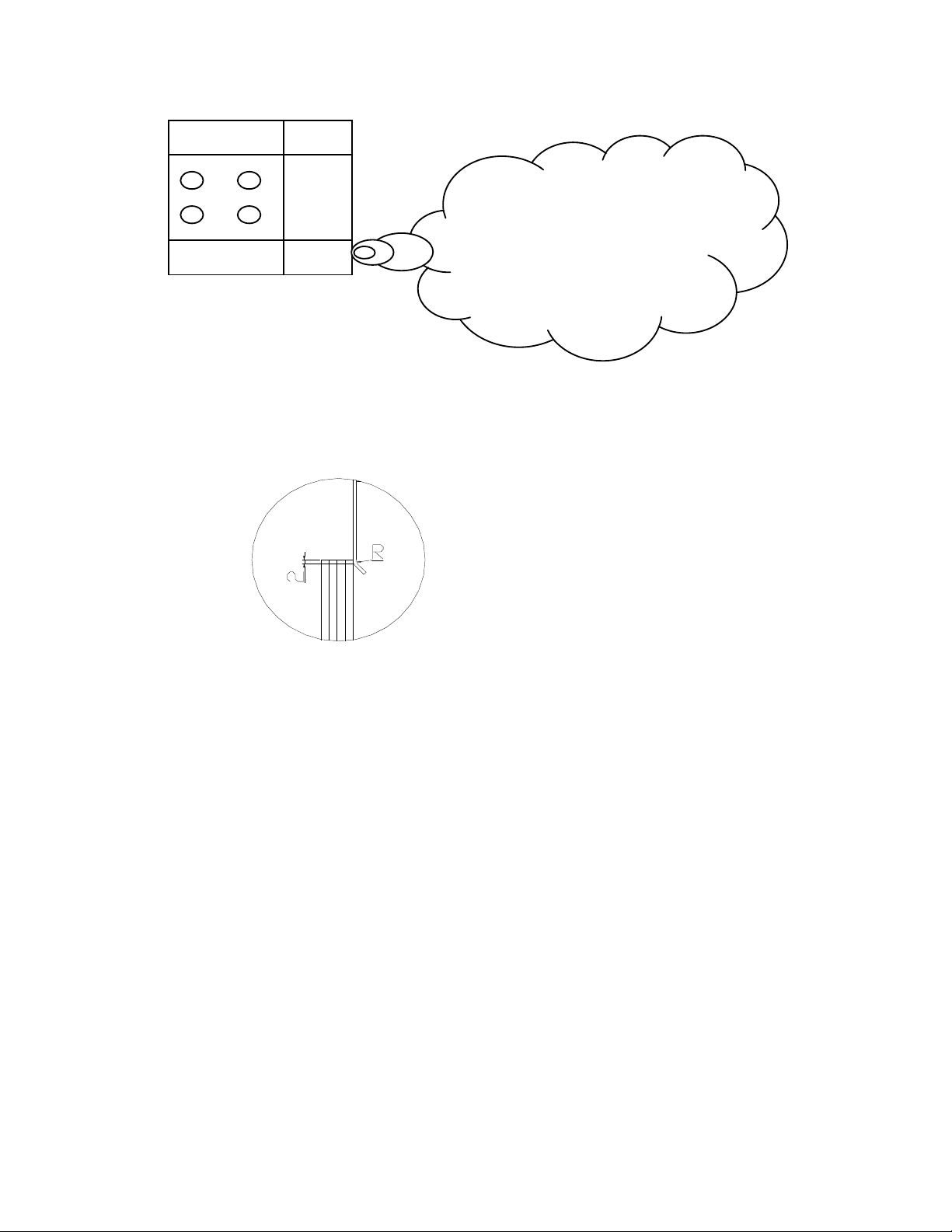
The vacuum cup can not
draw the case on the
folding line to prevent
from the air leaking.
a. After Up/Down stopper upward, the best distance is 2 mm between above
angle R and carton. If stopper is over high, carton. If stopper is over high, carton
will slip down or leap. If not, carton will not easy to be feed out due to strong
pressure.
b. Up/Down stopper position shouldn’t be against folding line.
c. The adjustment of Vacuum Cup can’t interfere other parts running.
d. The more Vacuum Cup to be used, better suction function. (As above drawing)
10.10. Trouble remedy: Press “ Alarm Reset” , solve trouble, then press “ Circle Motion”.

Page 12 of 36
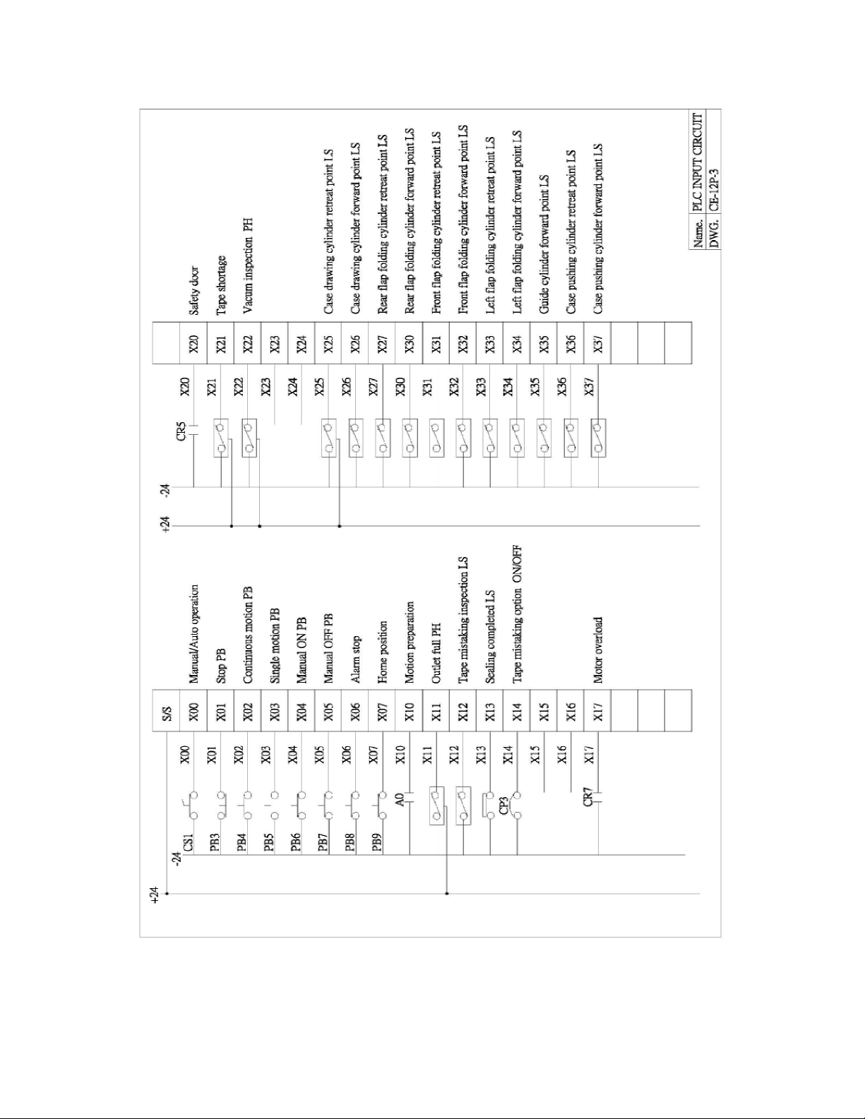
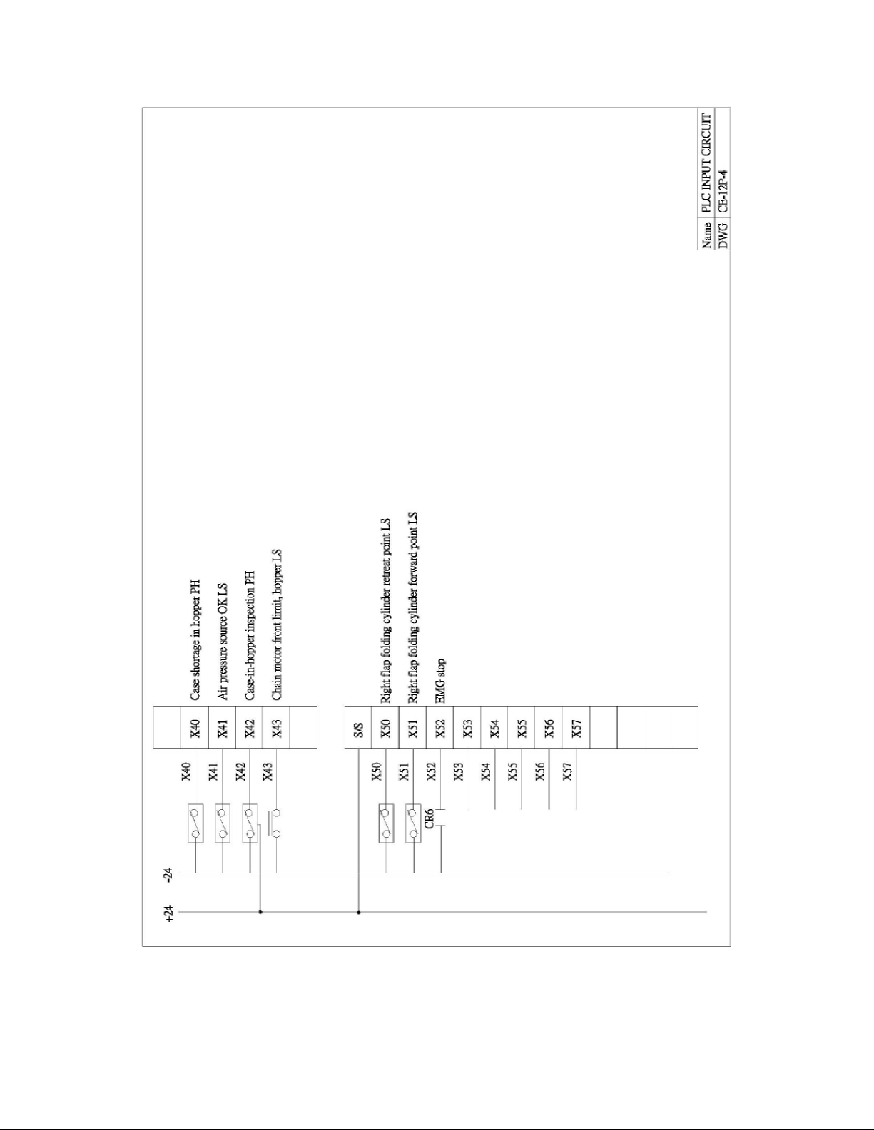
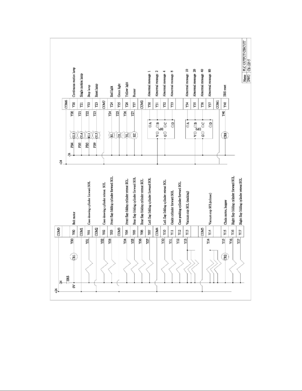
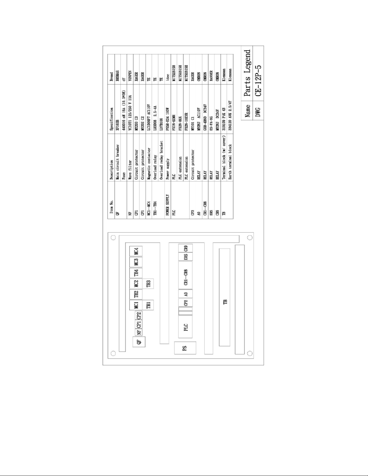
ELECTRIC CIRCUIT

Page 13 of 36
Page 14 of 36
Page 15 of 36
Page 16 of 36
Page 17 of 36

Page 18 of 36
Page 19 of 36
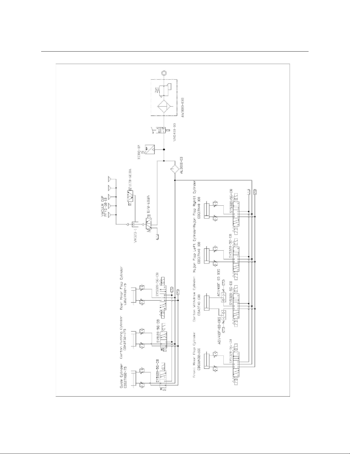
AIR PRESSURE CIRCUIT

Page 20 of 36
PNEUMATIC PART LIST
N9310-700
No. Part No. Description Q’ty
1. VM323-1 Vacuum pump 1
2. AW3000-03D Air lter 1
3. VHS400-03 Manual valve 1
4. IS300-02 Pressure inspecting switch 1
5. AL3000-03 Oil lter 1
6. SS5Y5-20-04 Solenoid valve w/ base 1
7. SS5Y5-20-03 Solenoid valve w/ base 1
8. SY5320-5G-C8 Solenoid valve 5
9. SY5120-5G-C8 Solenoid valve 2
10. 117B-611BA Solenoid valve 2
11. 101327601002 Pressure gauge 1
12. BVLC6-01 Closing valve 1
13. 33060806 Joint 1
14. 31260800 Adapt 1
15. 31260600 Adapt 2
FRONT FLAP FOLDING ASSEMBLY
M3303-20B
No. Part No. Description Q’ty
1. M3303-B01 Front ap folder 1
2. M3303-B02 Front ap folder mounting 1
3. M3303-B03 Bearing bushing 2
4. M3303-B04 Outfeed guide plate 1
5. Q1-201203 Washer 1
6. 81-3210 Cylinder 1
7. 81-3224 Cylinder 1
8. PHS10×1.25P Bearing 1
9. E00-2110 Ball bearing 2
Other manuals for CE-12P
1
Table of contents
Other Interpack Industrial Equipment manuals

Interpack
Interpack HSD2000 XS II Series User manual

Interpack
Interpack CE-12P User manual

Interpack
Interpack RSA 20-B User manual

Interpack
Interpack ETII+ LD User manual

Interpack
Interpack HSD2000 ET II RC User manual

Interpack
Interpack USA 2024-SB User manual

Interpack
Interpack USA 2024-SB DH User manual

Interpack
Interpack ipg RSA 2625-TB User manual


