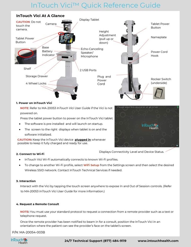
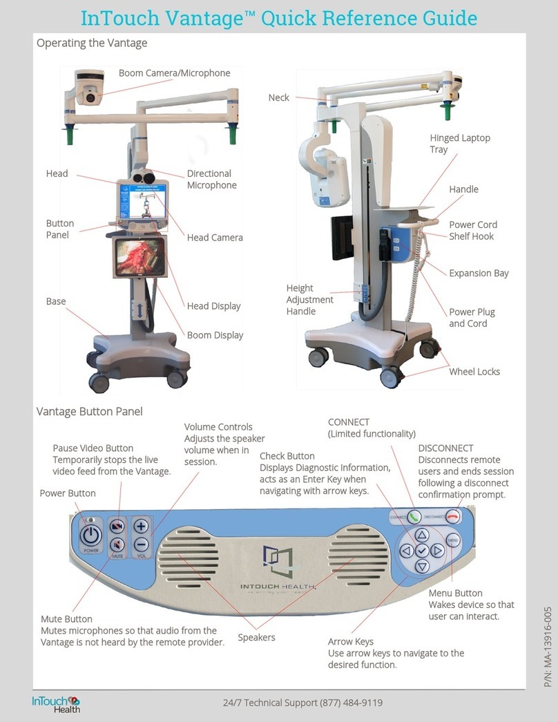
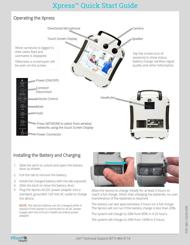
InTouch Health InTouch Lite 4 User manual

P/ N: MA-20084-002B
InTouch Lite™ 4
with Boom Camera
User Guide

Table of Contents
COPYRIGHT 5
SAFETY INSTRUCTIONS 7
User Profile 7
Notes, Cautions, and Warnings 7
Electromagnetic Compatibility - Guidance and Manufacturer's Declaration 9
Table 1: Electromagnetic Emissions 10
Table 2: Electromagnetic Immunity 11
Table 3: Electromagnetic Immunity 13
Table 4: Recommended separation distances 15
VIRTUAL CARE SYSTEM OVERVIEW 16
INTOUCH LITE 4 WITH BOOM CAMERA AND ITS INTENDED APPLICATION 18
InTouch Lite 4 with Boom Camera Indications for Use 18
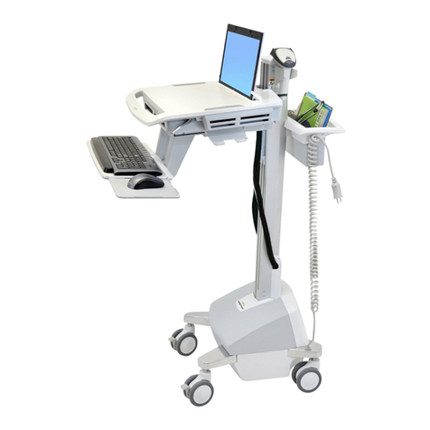
INTOUCH LITE4WITH BOOM CAMERA ANATOMY AND COMPONENTS 19
INTOUCH LITE 4 FEATURES 21
Adjusting the Head Height on an InTouch Lite 4 21
Adjusting the Boom 22
Moving the InTouch Lite 4 24
InTouch Lite 4 Main Power - Recharging the InTouch Lite 25
InTouch Lite 4 Head Display 27
InTouch Lite 4 with Boom Camera Idle Features (Out of Session) 27
InTouch Lite 4 with Boom Camera Settings Screens 30
InTouch Lite 4 with Boom Camera Wi-Fi Connection Setup 30
Connectivity Details 32
Device Cleaning Mode 32
Date and Time Settings Screen 33
Device Settings - More Options 34
Active Session Screen Navigation 36
Privacy Handset 38
Expansion Panel 38
Lite 4 Power On 41
Lite 4 Power Off 42
INTOUCH THERMAL CAMERA OVERVIEW (OPTIONAL) 44
InTouch Thermal Camera Indications for Use 44
InTouch Thermal Camera Statement of Intended Use 44
Intended Environment 44
- 2 -
24/7 Technical Support (877) 484-9119

Using the InTouch Thermal Camera View 45
Locally - Using Camera Preview 45
Check Thermal Differences 46
Thermal Map Palettes 46
Palette 1 47
Palette 2 47
Palette 3 47
Palette 4 47
Palette 5 48
Palette 6 48
Cleaning the InTouch Thermal Camera Lens 48
Thermal Camera Specifications 49
InTouch Thermal Camera Summary of Accuracy 50
InTouch Thermal Camera FDA Clearance 50
PATIENT ACCESS DEVICE - ERROR MESSAGES 51
CLEANING AND MAINTENANCE 53
Cleaning Instructions 53
Approved Disinfectants 54
Maintenance and Inspection 55
InTouch Lite 4 with Boom Camera Maintenance 55
INTOUCH LITE AND NETWORK INSTALLATION 56
Unpacking and Charging the Patient Access Device 56
Network Configuration 57
Configuring the InTouch Patient Access Device Wireless Connection 57
Non-Overlapping Channels 57
Transmitting Power 57
Interference 57
Security Options 57
NETWORK INSTALLATION 59
INTOUCH LITE 4 WITH BOOM CAMERA TECHNICAL SPECIFICATIONS 60
Performance 60
System Input Power Requirements 61
Classification 61
General Specifications 61
InTouch Lite 4 61
EMCClassifications 62
InTouch Lite 4 62
Environmental Specification for InTouch Lite 4 62
- 3 -
24/7 Technical Support (877) 484-9119

Copyright
© 2019 InTouch Technologies, Inc. All rights reserved. InTouch Lite 4 and this manual
contain information including, but not limited to, instructions, descriptions, definitions,
firmware and software, which are proprietary to InTouch Technologies, Inc. This
copyrighted information is protected under Title 17 of the United States Code. This
information shall not be copied, modified, or used in any manner which may violate any
rights of InTouch Technologies, Inc. InTouch Technologies, Inc. will strictly enforce all of
its rights to this information.
Patent(s):http:/ / www.intouchhealth.com/ patents
Speex Open Source Software includes:
Copyright 2002-2008 Xiph.org Foundation
Copyright 2002-2008 Jean-Marc Valin
Copyright 2005-2007 Analog Devices Inc.
Copyright 2005-2008 Commonwealth Scientific and Industrial Research
Organisation (CSIRO)
Copyright 1993, 2002,
2006
David Rowe
Copyright 2003 EpicGames
Copyright 1992-1994 Jutta Degener, Carsten Bormann
Redistribution and use in source and binary forms, with or without modification, are
permitted provided that the following conditions are met:
- Redistributions of source code must retain the above copyright notice, this list of
conditions and the following disclaimer.
- Redistributions in binary form must reproduce the above copyright notice, this list of
conditions and the following disclaimer in the documentation and/ or other materials
provided with the distribution.
- Neither the name of the Xiph.org Foundation nor the names of its contributors may be
used to endorse or promote products derived from this software without specific prior
written permission.
- 5 -
24/7 Technical Support (877) 484-9119

THIS SOFTWARE IS PROVIDED BY THE COPYRIGHT HOLDERS AND CONTRIBUTORS
“AS IS” AND ANY EXPRESS OR IMPLIED WARRANTIES, INCLUDING, BUT NOT LIMITED
TO, THE IMPLIED WARRANTIES OF MERCHANTABILITY AND FITNESS FOR A
PARTICULAR PURPOSE ARE DISCLAIMED. IN NO EVENT SHALL THE FOUNDATION OR
CONTRIBUTORS BE LIABLE FOR ANY DIRECT, INDIRECT, INCIDENTAL, SPECIAL,
EXEMPLARY, OR CONSEQUENTIAL DAMAGES (INCLUDING, BUT NOT LIMITED TO,
PROCUREMENT OF SUBSTITUTE GOODS OR SERVICES; LOSS OF USE, DATA, OR
PROFITS; OR BUSINESS INTERRUPTION) HOWEVER CAUSED AND ON ANY THEORY OF
LIABILITY, WHETHER IN CONTRACT, STRICT LIABILITY, OR TORT (INCLUDING
NEGLIGENCE OR OTHERWISE) ARISING IN ANY WAY OUT OF THE USE OF THIS
SOFTWARE, EVEN IF ADVISED OF THE POSSIBILITY OF SUCH DAMAGE.
Microsoft® and Windows® are either registered trademarks or trademarks of Microsoft
Corporation in the United States and/ or other countries.
Last updated: December, 2019
- 6 -
24/7 Technical Support (877) 484-9119

Safety Instructions
User Profile
Trained healthcare professionals are the intended users of any InTouch Health Patient
Access Device. Users of the system require clinical judgment and experience to review
and interpret the patient data transmitted.
Notes, Cautions, and Warnings
CAUTION: Federal law restricts this device to sale by or on the order of a
physician.
Information in ORANGE BOLDFACED TYPE throughout this User Guide should be
interpreted in the following context:
NOTE: Provides supplementary information for facilitating operation of the
system.
CAUTION: Presents instructions for avoiding damage to the system.
WARNING: Disregarding this information may prove hazardous to the safety of a
person near the InTouch Health Patient Access Device.
Wireless Transmitter Notification – Non-ionizing
electromagnetic radiation. This device communicates over
the 802.11 ac/a/b/g/n standard for wireless communication.
Pinch Point — Avoid the labeled pinch point on the
rear of the display of the InTouch Lite 4.
Avoid the labeled pinchpoint between the camera and
the first boom joint when the boom is folded to a
storage position.
Body Float—Type B. A Type B piece of equipment is one that
provides a particular degree of protection against electric
shock, particularly regarding allowable leakage current and
reliability of the protective earth connection (grounding).
- 7 -
24/7 Technical Support (877) 484-9119

Consult Operator's Manual – Operating Instructions
are contained in a separate instruction manual.
Do not push or lean – Do not push on cart when it is
prevented from lateral movement by an obstruction.
Tipping Hazard – Do not pull down on the Boom. Fold and
lower the Boom to storage position to transport.
- 8 -
24/7 Technical Support (877) 484-9119

Electromagnetic Compatibility - Guidance and
Manufacturer's Declaration
The InTouch Lite system complies with IEC 60601-1- 2 4th edition, General
Requirements for Safety—Collateral Standard: Electromagnetic compatibility.
Performance of the device is unaffected by exposure to the compliance levels
described in Tables 1,2,3 and 4 in the following section.
Special precautions and installation information for the InTouch Lite for electromagnetic
compatibility (EMC) are provided below:
lEquipment in hospital environments, including the InTouch Lite and other portable
or mobile communications equipment, can produce Electromagnetic Interference
(EMI), which may affect the function of these devices. Such effects are prevented
by use of equipment with EMI characteristics proven below recognized limits, as
identified in the tables below.
lIn the event of suspected interference from other equipment, which prevents the
proper functioning of the InTouch Lite, contact InTouch Health and discontinue use
of the system until the problem can be remedied.
The following tables contain the Manufacturer’s declaration and additional information
required by IEC 60601-1-2.
- 9 -
24/7 Technical Support (877) 484-9119

Table 1: Electromagnetic Emissions
The InTouch Lite is intended for use in the electromagnetic environment specified
below. The customer or the user of the InTouch Lite should assure that it is used in
such an environment.
Emissions Test Compliance Electromagnetic Environment
RF Emissions
CISPR 11
Group 1 The InTouch Lite uses RF energy only for its internal
function. Therefore, its RF emissions are very low and
are not likely to cause any interference in nearby
electronic equipment.
RF Emissions
CISPR 11
Class A The InTouch Lite is suitable for use in all establishments
other than domestic and those directly connected to
the public low-voltage power supply network that
supplies buildings used for domestic purposes.
Harmonic
Emissions IEC
61000-3-2
Class A
Voltage
Fluctuations /
Flicker Emissions
IEC 61000-3-3
Complies
- 10 -
24/7 Technical Support (877) 484-9119

Table 2: Electromagnetic Immunity
The InTouch Lite system is intended for use in the electromagnetic environment
specified below. The customer or the user of the InTouch Lite should assure that it is
used in such an environment.
Immunity Test EC 60601 Test
Level
Compliance
Level
Electromagnetic Environment -
Guidance
Electrostatic
Discharge (ESD)
IEC 61000-4-2
±8 kV Contact
±15 kV Air
±8 kV
Contact
±15 kV Air
Floors should be wood, concrete or
ceramic tile. If floors are covered with
synthetic material, the relative humidity
should be at least 30%.
Electrical Fast
Transient / Burst
IEC 61000-4-4
±2 kV for Power
Supply Lines
±1 kV for Input /
Output Lines
±2 kV for
Power
Supply Lines
±1 kV for
Input /
Output Lines
Mains power quality should be that of a
typical commercial or hospital
environment.
Surge IEC
61000-4-5
±1 kV Line(s) to
Line(s)
±2 kV Line(s) to
Earth
±1 kV Line(s)
to Line(s)
±2 kV Line(s)
to Earth
Mains power quality should be that of a
typical commercial or hospital
environment.
Voltage Dips,
Short
Interruptions,
and Voltage
Variations on
Power Supply
Input Lines IEC
61000-4-11
<5% UT (>95%
dip in UT) for 0.5
cycle
40% UT (60%
dip in UT) for 5
cycles
70% UT (30%
dip in UT) for 25
cycles
<5% UT (>95%
dip in UT) for 5
sec
<5% UT (>95%
dip in UT) for
0.5 cycle
40% UT (60%
dip in UT) for
5 cycles
70% UT (30%
dip in UT) for
25 cycles
<5% UT (>95%
dip in UT) for
5 sec
Mains power quality should be that of a
typical commercial or hospital
environment. If the user of the device
requires continued operation during
power mains interruptions, it is
recommended that the Patient Access
Device be powered from an
uninterruptible power supply (UPS) or
a battery.
- 11 -
24/7 Technical Support (877) 484-9119

Immunity Test EC 60601 Test
Level
Compliance
Level
Electromagnetic Environment -
Guidance
Power
Frequency
(50/ 60 Hz)
Magnetic
Field
IEC 61000-4-8
30 A/m 30 A/m Power frequency magnetic fields
should be at levels characteristic of a
typical location in a typical commercial
or hospital environment.
UT is the a.c. mains voltage prior to application of the test level.
- 12 -
24/7 Technical Support (877) 484-9119

Table 3: Electromagnetic Immunity
InTouch Lite is intended for use in the electromagnetic environment specified below.
The customer or the user of an InTouch Lite should assure that it is used in such an
environment.
Immunity Test EC 60601 Test Level Compliance
Level
Electromagnetic Environment -
Guidance
Conducted RF
IEC 61000-4-6
Radiated FR
IEC 61000-4-3
3 Vrms 150 kHz to 80
MHz
6V in ISM bands
between 150kHz and
80MHz
3 V/ m 80
MHz to 2.5
GHz
3 Vrms 150 kHz
to 80 MHz
6V in ISM
bands between
150kHz and
80MHz
3 V/ m 80 MHz
to 2.5 GHz
Portable and mobile RF
communications equipment should be
used no closer to any part of the
InTouch Lite, including cables, than
the recommended separation distance
calculated from the equation
applicable to the frequency of the
transmitter. Recommended separation
distance:
d= 1.2
d= 1.2
d= 2.3
where P is the maximum output power
rating of the transmitter in watts (W)
according to the transmitter
manufacturer and d is the
recommended separation distance in
meters (m). Field strengths from fixed
RF transmitters, as determined by an
electromagnetic site surveya, should
be less than the compliance level in
each frequency rangeb.
Interference may occur in the vicinity
of equipment marked with the
following symbol:
NOTES:
1. At 80 MHz and 800 MHz, the higher frequency range applies.
2. These guidelines may not apply in all situations. Electromagnetic propagation is
affected by absorption and reflection from structures, objects, and people.
80 MHz to 800 MHz
800 MHz to 2.5 GHz
- 13 -
24/7 Technical Support (877) 484-9119

Immunity Test EC 60601 Test Level Compliance
Level
Electromagnetic Environment -
Guidance
a. Field strengths from fixed transmitters, such as base stations for radio (cellular/ cordless)
telephones and land mobile radios, amateur radio, AM and FM radio broadcast, and TV
broadcast cannot be predicted theoretically with accuracy. To assess the electromagnetic
environment due to fixed RF transmitters, an electromagnetic site survey should be
considered. If the measured field strength in the location in which the InTouch Lite is used
exceeds the applicable RF compliance level above, the InTouch Lite should be observed to
verify normal operation. If abnormal performance is observed, additional measures may be
necessary, such as re-orienting or relocating the InTouch Lite.
b. Over the frequency range 150 kHz to 80 MHz, field strengths should be less than [3] V/ m.
- 14 -
24/7 Technical Support (877) 484-9119

Table 4: Recommended separation distances
Recommended separation distances between portable and mobile RF
communications equipment and the InTouch Lite.
The InTouch Lite is intended for use in an electromagnetic environment in which
radiated RF disturbances are controlled. The customer or the user of the InTouch Lite
can help prevent electromagnetic interference by maintaining a minimum distance
between portable and mobile RF communications equipment (transmitters) and the
InTouch Lite as recommended below, according to the maximum output power of the
communications equipment.
Rated Maximum Output
Power of
Transmitter
(W)
Separation distance according to frequency of
transmitter
(m)
150 kHz to 80
MHz
d =1.2
80 MHz to 800
MHz d =1.2
800 MHz to 2.5
GHz d= 2.3
0.01 0.12 0.12 0.23
0.1 0.38 0.38 0.73
1 1.2 1.2 2.3
10 3.8 3.8 7.3
100 12 12 23
For transmitters rated at a maximum output power not listed above, the recommended
separation distance d in meters (m) can be estimated using the equation applicable to
the frequency of the transmitter, where P is the maximum output power rating of the
transmitter in watts (W) according to the transmitter manufacturer.
NOTES
1. At 80 MHz and 800 MHz, the separation distance for the higher frequency
range applies.
2. These guidelines may not apply in all situations. Electromagnetic
propagation is affected by absorption and reflection from structures,
objects and people.
- 15 -
24/7 Technical Support (877) 484-9119

Virtual Care System Overview
Health systems now view virtual care as an extension of their services, relying on a
combination of software, hardware, networks, systems, and people to work together to
deliver improved access, quality, and care to their patients.
Enabling healthcare’s only integrated virtual care platform, InTouch Health powers
virtual visits within your clinics, healthcare facilities, or even your patients’ home for an
integrated experience across a multitude of use cases, environments, and budgets.
Built on our cloud-based network, Solo™ by InTouch, our next generation software
platform, is the backbone to delivering care anywhere, anytime. Solo by InTouch
provides users with everything they need to streamline their telehealth needs for fast
user adoption and program growth.
- 16 -
24/7 Technical Support (877) 484-9119

With Solo by InTouch as your virtual care foundation, connect people, healthcare
systems, HIT systems, devices, and third-party software applications to enable
telehealth solutions across the patient care journey. Whether launching a scheduled visit
from your EMR, providing care for patients at home or in a clinic, Solo by InTouch
provides a core set of tools to easily deliver virtual care and provide users with an
immersive, patient- centric view of their clinical workflows.
Purpose-built for healthcare. Designed with the
security and reliability you need
Our cloud-based, patented network ensures the industry’s highest connection success
rate and meets industry-defined requirements for protecting and securing sensitive
healthcare information. Our downloadable and web- based platform allows users to
access virtual care across a broad range of consumer and telehealth devices in any
clinical setting.
Within a single platform, users are in control of their virtual experience with a
configurable dashboard to meet the unique set of preferences for every user. Layer Solo
by InTouch into your existing HIT system investments or use it as the foundation to close
your workflow gaps with our software modules, creating a solution unique to you.
- 17 -
24/7 Technical Support (877) 484-9119

InTouch Lite 4 with Boom Camera and Its
Intended Application
The InTouch Lite 4 with Boom Camera is a clinical communications tool that provides a
means of transmitting, receiving, and storing real-time audio, video and patient data.
InTouch Lite 4 with Boom Camera may also be used in conjunction with 510(k)-cleared
devices that transmit patient biometric data including vital signs information. The
InTouch Lite 4 with Boom Camera transmits and receives information over a high-speed
connection between patients and health professionals. The InTouch Lite 4 with Boom
Camera can be used for communications in both low and high acuity clinical
environments, e.g. pre-, peri-operative and post- surgical, cardiovascular, neurological,
prenatal, psychological and critical care assessments and examinations. Clinical
judgment and experience are required to review and interpret the information
transmitted.
InTouch Lite 4 with Boom Camera Indications for Use
The InTouch Lite 4 with Boom Camera is used in telecommunications for a variety of
clinical applications. These applications include, but are not limited to: cardiovascular,
neurological, behavioral health, neonatal, etc., use cases. The InTouch Lite 4 with Boom
Camera does not diagnose health care conditions but instead provides the means for
the remote physician to administer his or her assessments and examinations. The
InTouch Lite 4 with Boom Camera is intended for use in both low and high acuity use
cases .
- 18 -
24/7 Technical Support (877) 484-9119

InTouch Lite4with Boom Camera Anatomy and
Components
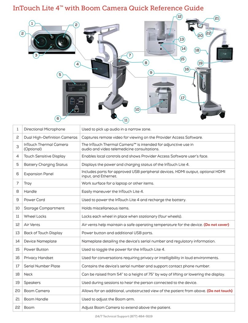
1 Directional
Microphone
Used to pick up audio in a narrow zone.
2 Dual High-
Definition
Cameras
Captures remote video for viewing on the Provider Access Software.
3 InTouch Thermal
Camera
(Optional)
The InTouch Thermal Camera™ is intended for adjunctive use in
audio and video telemedicine consultations.
4 Touch Sensitive
Display
Enables local controls and shows Provider Access Software user’s
face.
5 Battery Charging
Status
Displays the power and charging status of the InTouch Lite 4.
6 Expansion Panel Includes ports for approved USB peripheral devices, HDMI output,
optional HDMI input, and Ethernet.
7 Tray Work surface for a laptop or other items.
- 19 -
24/7 Technical Support (877) 484-9119

8 Handle Easily maneuver the InTouch Lite 4.
9 Power Cord Used to power the InTouch Lite 4 and recharge the battery.
10 Storage
Compartment
Holds miscellaneous items.
11 Wheel Locks Locks each wheel in place when stationary (four wheels).
12 Air Vents Air vents help maintain a safe operating temperature for the device.
(Do not cover)
13 Back of Touch
Display
Power button and additional USB ports.
14 Device
Nameplate
Nameplate detailing the device’s serial number and regulatory
information.
15 Power Button Used to toggle the power for the InTouch Lite 4.
16 Privacy Handset Used for conversations requiring privacy or intelligibility in loud
environments.
17 Serial Number
Plate
Contains the device’s serial number and support contact phone
number.
18 Neck Can be raised from 54” to a height of 75” by way of lifting or lowering
the display.
19 Speakers Used during sessions to hear the person connected to the device.
20 Boom Camera Allows for an additional, unobstructed view of the patient from
above. (Do not touch).
21 Boom Handle Used to adjust the Boom arm.
22 Boom Adjust Boom Camera to extend above the patient.
- 20 -
24/7 Technical Support (877) 484-9119
Other manuals for InTouch Lite 4
1
Table of contents
Other InTouch Health Medical Equipment manuals
Popular Medical Equipment manuals by other brands
Medistore
Medistore ProCair Digital 5000 Quick setup guide

Ultrasonix
Ultrasonix Sonix MDP Service manual
Smith & Nephew
Smith & Nephew BIRMINGHAM HIP SURGICAL TECHNIQUE

Breas Medical
Breas Medical NIPPY 3 PLUS instruction manual
Huntleigh
Huntleigh Baby DOPPLEX 4000 user manual
Boston Scientific
Boston Scientific EASYTRAK 2 IS-1 Physician's lead manual
Invacare
Invacare Platinum IRC5LXO2 Operator's manual
Cincinnati Sub-Zero
Cincinnati Sub-Zero NORM-O-TEMP Operation manuals
Storz
Storz Endo-Arthroflator VET instruction manual
Vaunn Medical
Vaunn Medical M725N-DLWH-CHVM user manual
AGFA
AGFA DR 800 user manual
Delfi
Delfi P.T.S. Operator and maintenance manual

