manuals.online logo
Brands
  1. Home
  2. •
  3. Brands
  4. •
  5. IOTA
  6. •
  7. Lighting Equipment
  8. •
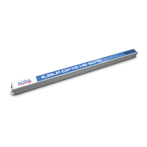
  9. IOTA ILBLP SP18 HE SD LC CW User manual

IOTA ILBLP SP18 HE SD LC CW User manual

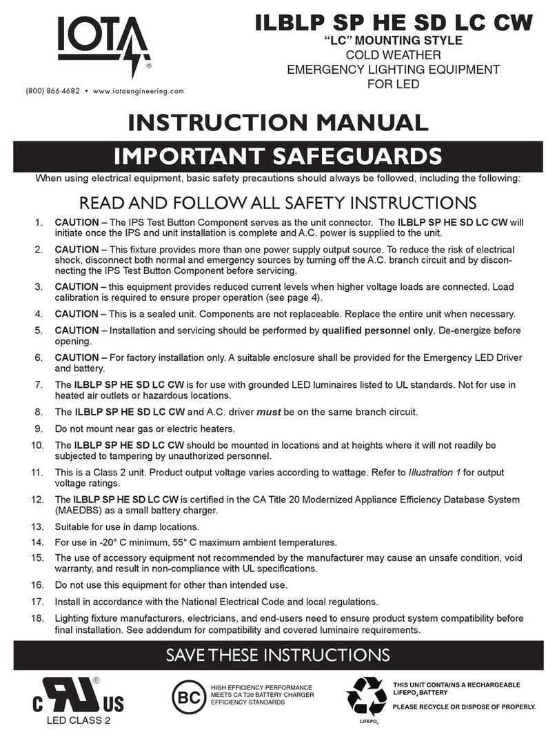
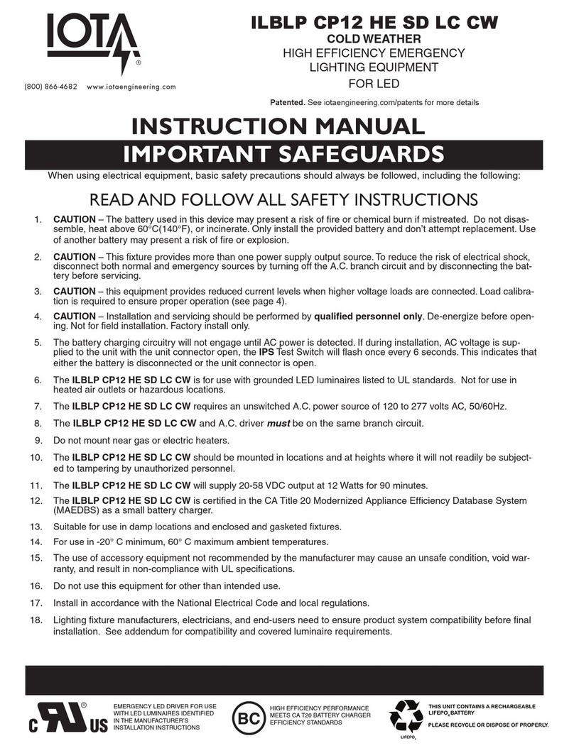
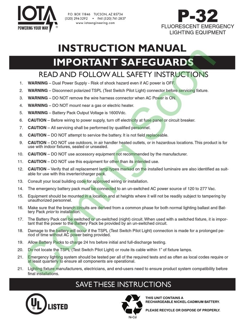
IMPORTANT SAFEGUARDS
When using electrical equipment, basic safety precautions should always be followed, including the following:
READ AND FOLLOW ALL SAFETY INSTRUCTIONS
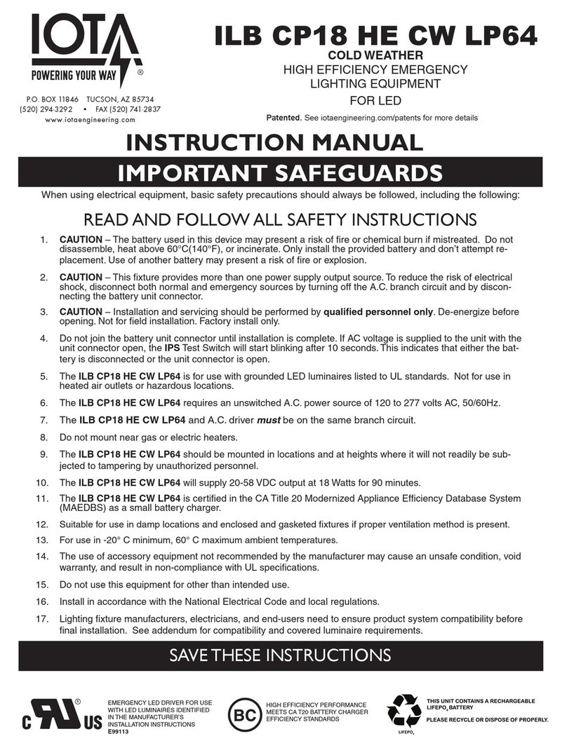
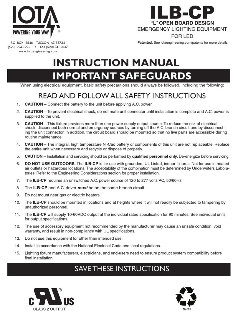
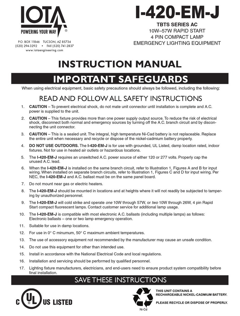
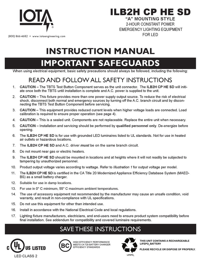
1. CAUTION – The battery used in this device may present a risk of fire or chemical burn if mistreated. Do not disas-
semble, heat above 60°C(140°F), or incinerate. Only install the provided battery and don’t attempt replacement. Use
of another battery may present a risk of fire or explosion.
2. CAUTION – This fixture provides more than one power supply output source. To reduce the risk of electrical shock,
disconnect both normal and emergency sources by turning off the A.C. branch circuit and by disconnecting the bat-
tery before servicing.
3. CAUTION – this equipment provides reduced current levels when higher voltage loads are connected. Load calibra-
tion is required to ensure proper operation (see page 4).
4. CAUTION – Installation and servicing should be performed by qualified personnel only. De-energize before open-
ing. Not for field installation. Factory install only.
5. The battery charging circuitry will not engage until AC power is detected. If during installation, AC voltage is sup-
plied to the unit with the unit connector open, the IPS Test Switch will flash once every 6 seconds. This indicates that
either the battery is disconnected or the unit connector is open.
6. The ILBLP SP18 HE SD LC CW is for use with grounded LED luminaires listed to UL standards. Not for use in
heated air outlets or hazardous locations.
7. The ILBLP SP18 HE SD LC CW requires an unswitched A.C. power source of 120 to 277 volts AC, 50/60Hz.
8. The ILBLP SP18 HE SD LC CW and A.C. driver must be on the same branch circuit.
9. Do not mount near gas or electric heaters.
10. The ILBLP SP18 HE SD LC CW should be mounted in locations and at heights where it will not readily be subject-
ed to tampering by unauthorized personnel.
11. The ILBLP SP18 HE SD LC CW will supply 20-58 VDC output 18W (initial) for 90 minutes.
12. The ILBLP SP18 HE SD LC CW is certified in the CA Title 20 Modernized Appliance Efficiency Database System
(MAEDBS) as a small battery charger.
13. Suitable for use in damp locations and enclosed and gasketed fixtures.
14. For use in -20° C minimum, 60° C maximum ambient temperatures.
15. The use of accessory equipment not recommended by the manufacturer may cause an unsafe condition, void war-
ranty, and result in non-compliance with UL specifications.
16. Do not use this equipment for other than intended use.
17. Install in accordance with the National Electrical Code and local regulations.
18. Lighting fixture manufacturers, electricians, and end-users need to ensure product system compatibility before final
installation. See addendum for compatibility and covered luminaire requirements.
SAVE THESE INSTRUCTIONS
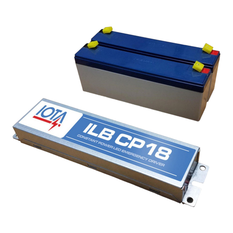
ILBLP SP18 HE SD LC CW
COLD WEATHER
HIGH EFFICIENCY EMERGENCY
LIGHTING EQUIPMENT
FOR LED
INSTRUCTION MANUAL
(800) 866-4682 www.iotaengineering.com
Patented. See iotaengineering.com/patents for more details
HIGH EFFICIENCY PERFORMANCE
MEETS CA T20 BATTERY CHARGER
EFFICIENCY STANDARDS
EMERGENCY LED DRIVER FOR USE
WITH LED LUMINAIRES IDENTIFIED
IN THE MANUFACTURER’S
INSTALLATION INSTRUCTIONS
Page 2
VERIFYING COMPATIBILITY
The ILBLP SP18 HE SD LC CW can be used with most LED loads that operate at 20-58 VDC up to a load rating of
18 Watts (initial).
1. The ILBLP SP18 HE SD LC CW series has been evaluated to and found compliant to UL standard 924. The as-installed
performance of system must meet or exceed all Federal, State, and Local code requirements.
CAUTION: Before installing, make certain A.C. power is off and the battery unit connector is
disconnected.
STEP 1 - MOUNTING THE ILBLP SP18 HE SD LC CW
Mount the ILBLP SP18 HE SD LC CW in the driver/lamp compartment or enclosed wireway so the wire leads are
not exposed, at least ½″away from the AC Driver.
The battery must be mounted securely. Once the battery is secure, join the 4-pin battery connector and 2-pin unit connector.
INSTALLATION INSTRUCTIONS
STEP 2 - WIRING TO THE LED LOAD AND NORMAL DRIVER
Refer to the appropriate wiring diagram below. Make sure all connections are in accordance with NEC and any other
local requirements.
ILB CP CW - SINGLE LEAD ACID BATTERY CONFIGURATION - WIRING TO LOAD AND NORMAL DRIVER
ILB CP CW 1LA.EPS
AC (NORMAL)
DRIVER
IOTA ILB CP CW
EMERGENCY DRIVER
LED
LOAD
BLACK
BLACK/WHITE RED (+)
BLUE/WHITE (-)
RED/WHITE (+)
LED INPUT(-)
LED INPUT (+)LED OUTPUT (+)
LED OUTPUT (-)
STEP 3 - INSTALLING THE BATTERIES
ILB CP CW - LITHIUM 6 X 4 CONFIGURATION
ILB CP CW LP64.EPS
IOTA ILB CP CW
EMERGENCY DRIVER
BATTERY
RED (+)
RED (+)
BLACK(-)
BLACK(-)
-
-
+
+
UNIT CONNECTOR
4-PIN BATTERY CONNECTOR
ILBLP SP CW
ILBLP SP CW
Page 3
ILB CP CW - SINGLE LEAD ACID BATTERY CONFIGURATION - TEST SWITCH CONNECTIONS
ILB CP CW 1LA.EPS
IPS
TEST ACCESSORY
BROWN
VIOLET
WHT
RED
CHANNEL COVER
IPS
EMERGENCY
DRIVER
LUMINAIRE HOUSING
IPS NUT
STEP 4 - INSTALLING THE IP RATED TEST SWITCH (IPS)
A. Locate a suitable location for the IPS
and cable that is visible outside the
fixture. Drill or punch a 0.537" diameter
hole in the fixture wall or wireway cover.
Insert the IPS into the hole so that the
LED test button/pilot light is located
outside of the fixture.
B. Secure the IPS using the
IPS nut.
C. Connect the IPS White wire to the
Brown lead on the ILBLP. Then
connect the IPS Red wire to the
Violet lead.
COMPLETING INSTALLATION
STEP 6 - APPLY AC POWER
A. Apply continuous AC power to the unit. Allow the unit to charge for at least 1 hour before performing a functional test.
B. Verify that the IPS light is steady RED indicating that the AC power is active and no faults are detected.
C. Press and hold the IPS button for two seconds then release. The LED Module should be operating in the emergency mode
at the rated light output. If the LED Module in the fixture returns to normal operation after the test sequence completes, the
unit is ready for normal and emergency service. If not, contact Customer Service.
This unit features AC Activate technology that keeps the battery disengaged until the the presence of AC power is detected
to charge the battery. Thus, in STEP 3, when AC power o󰀨, it is possible to join the UNIT CONNECTOR without triggering
emergency mode and allowing completion of the installation without discharging the battery
OPERATION
Normal Mode
A.C. power is present. The A.C. Driver operates the LED Module as intended. The ILBLP SP18 HE SD LC CW is in the
standby charging mode. The IPS will be lit providing a visual indication of the unit status (refer to Table A).
Emergency Mode
The A.C. power fails. The ILBLP SP18 HE SD LC CW senses the A.C. power failure and automatically switches to the Emer-
gency Mode. The LED Module is illuminated for a minimum of 90 minutes. When the A.C. power is restored, the ILBLP SP18
HE SD LC CW switches the system back to the Normal Mode and resumes battery charging.
ILB CP CW - SINGLE LEAD ACID BATTERY CONFIGURATION - CONNECTING AC INPUT
ILB CP CW 1LA.EPS
IOTA ILB CP CW
EMERGENCY DRIVER
WHITE
BLACK
COMMON
UNSWITCHED
24/7 POWER
BLK/ORG (120 TO 277V, 50/60HZ)
SWITCHED OR
UNSWITCHED HOT
STEP 5 - WIRING THE AC INPUT
The ILBLP SP18 HE SD LC CW requires an unswitched AC input of 120/277 volts. Connect the BLACK/ORANGE wire to
the unswitched 120/277 Line, and the WHITE wire to the Neutral. Connect the BLACK wire to a switched or unswitched
AC input of 120/277 volts.
ILBLP SP CW
PANEL CUTOUT
0.537 in - 0.545 in
ILBLP SP CW
Page 4
68018-118
REV 2200
ILB CP CW - LITHIUM 6 X 4 CONFIGURATION
ILB CP CW LP64.EPS
AC (NORMAL)
DRIVER
IOTA ILB CP CW
EMERGENCY DRIVER
LED
LOAD
BATTERY
BLACK
WHITE
BLACK
BLACK/WHITE
COMMON
UNSWITCHED
24/7 POWER
BLK/ORG (120 TO 277V, 50/60HZ)
WHITE
SWITCHED OR
UNSWITCHED
HOT
IPS
TEST ACCESSORY
RED (+)
BLUE/WHITE (-)
RED/WHITE (+)
LED INPUT(-)
LED INPUT (+)LED OUTPUT (+)
LED OUTPUT (-)
BROWN
VIOLET
RED (+)
RED (+)
BLACK(-)
BLACK(-)
-
-
+
+
WHT
RED
UNIT CONNECTOR
4-PIN BATTERY CONNECTOR
TESTING & MAINTENANCE
COMPLETE WIRING DIAGRAM
Automatic Testing
The ILBLP SP18 HE SD LC CW is designed to automati-
cally test the emergency function for 60 seconds each
month, and 90 minutes every 12 months.
Self-testing works in conjunction with the IPS indicator as-
sembly. Any detected failures will be indicated by ashing
of the LED indicator. See Table A for diagnosis:
Manual Testing
Manual testing of the ILBLP SP18 HE SD LC CW can be
performed by pressing and holding the IPS test button for
2 seconds then releasing it to start a 60-second test. Only
initiate a manual test when the IPS status indicator shows
no faults (see table A). Testing can be cancelled by holding
the IPS test button pressed for 2 seconds then releasing.
Load Calibration
To ensure proper operation, Load Calibration is required whenever the LED load connected to the ILBLP SP18 HE SD LC CW
is changed. Note: Load Calibration happens automatically 48 hours after the ILBLP SP18 HE SD LC CW is rst installed or
reinitialized (See Maintenance section below). If after installation, the connected LED load is changed, Load Calibration will
need to be performed. To manually initiate Load Calibration, press and hold the IPS button for 20 seconds. After 20 seconds,
the LED load will transition to emergency power. Release the IPS button. During calibration, the LED load will stay in emer-
gency power and the IPS will be o󰀨 for 60 seconds. Any failures detected during Load Calibration will be indicated on the IPS
(see Table A).
Maintenance
When performing maintenance on the ILBLP SP18 HE SD LC CW or the emergency luminaire, the ILBLP SP18 HE SD LC
CW battery circuit must be completely powered down by performing the following steps:
1) Disconnect AC power. The ILBLP SP18 HE SD LC CW will enter EMERGENCY MODE.
2) Disconnect the battery circuit through one of the following methods:
Method 1: At any point during emergency mode, hold the IPS test button pressed for 2 seconds then release it. After releasing
the button, the LED module should turn o󰀨 indicating the battery is no longer powering the electronics.
Method 2: Disconnect the 2-pin unit connector.
Method 3: Disconnect the 4-pin battery connector.
Once all power sources are disconnected from the ILBLP SP18 HE SD LC CW and emergency luminaire, proceed with re-
quired maintenance.
When maintenance is complete, reconnect the 2-pin and/or 4-pin connectors (if unplugged through one of the methods above)
and restore AC power to the emergency luminaire. The AC Activate circuitry will detect the presence of AC power and automati-
cally reconnect the battery to the ILBLP SP18 HE SD LC CW electronics.
Table A: IPS Diagnostic Codes
CONDITIONSTATUS INDICATION
STEADY REDAC PRESENT / NO FAULTS DETECTED
OFF EMERGENCY MODE / TESTING
FLASHING RED (ONCE PER SECOND)
DISCONNECTED BATTERY / LOW BATTERY
1 RED FLASH (EVERY 6 SECONDS)
2 RED FLASHES (EVERY 6 SECONDS) EMERGENCY LED LOAD FAILURE
UNABLE TO CHARGE
ILBLP SP CW

Other IOTA Lighting Equipment manuals

IOTA P-40 User manual

IOTA

IOTA P-40 User manual

IOTA ILBLP CP07 HE SD BP User manual

IOTA

IOTA ILBLP CP07 HE SD BP User manual

IOTA ILBLP CP HE SD LC CW User manual

IOTA

IOTA ILBLP CP HE SD LC CW User manual

IOTA I-320 User manual

IOTA

IOTA I-320 User manual

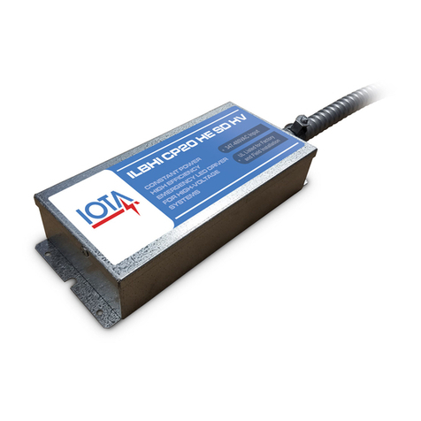
IOTA ILBHI CP HE SD HV User manual

IOTA

IOTA ILBHI CP HE SD HV User manual

IOTA ILBHI CP 2H HE SD HV User manual

IOTA

IOTA ILBHI CP 2H HE SD HV User manual

IOTA ILBLP CP12 HE SD LC CW User manual

IOTA

IOTA ILBLP CP12 HE SD LC CW User manual

IOTA ILB-CP Series User manual

IOTA

IOTA ILB-CP Series User manual

IOTA P-32 User manual

IOTA

IOTA P-32 User manual

IOTA ILB2H CP HE SD HV User manual

IOTA

IOTA ILB2H CP HE SD HV User manual

IOTA ILB-CP20-HE-SD-S User manual

IOTA

IOTA ILB-CP20-HE-SD-S User manual

IOTA ILB-CP User manual

IOTA

IOTA ILB-CP User manual

IOTA D Series User manual

IOTA

IOTA D Series User manual

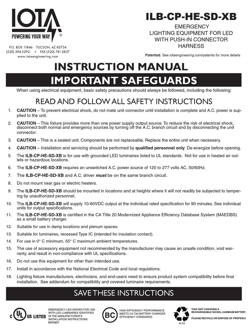
IOTA ILB-CP-HE-SD-XB User manual

IOTA

IOTA ILB-CP-HE-SD-XB User manual

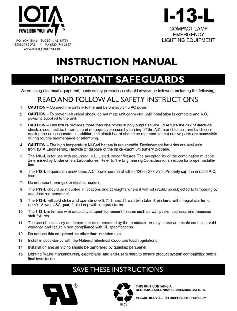
IOTA I-13-L User manual

IOTA

IOTA I-13-L User manual

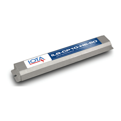
IOTA ILBLP CP10 User manual

IOTA

IOTA ILBLP CP10 User manual

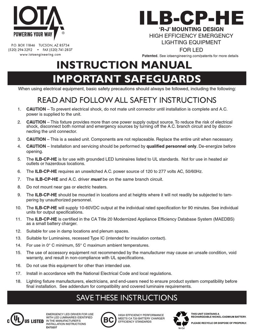
IOTA ILB-CP-HE Series User manual

IOTA

IOTA ILB-CP-HE Series User manual

IOTA ILB CP07 HE User manual

IOTA

IOTA ILB CP07 HE User manual

IOTA ILB-LP-CP-HE-SD-HV User manual

IOTA

IOTA ILB-LP-CP-HE-SD-HV User manual

IOTA D Series User manual

IOTA

IOTA D Series User manual

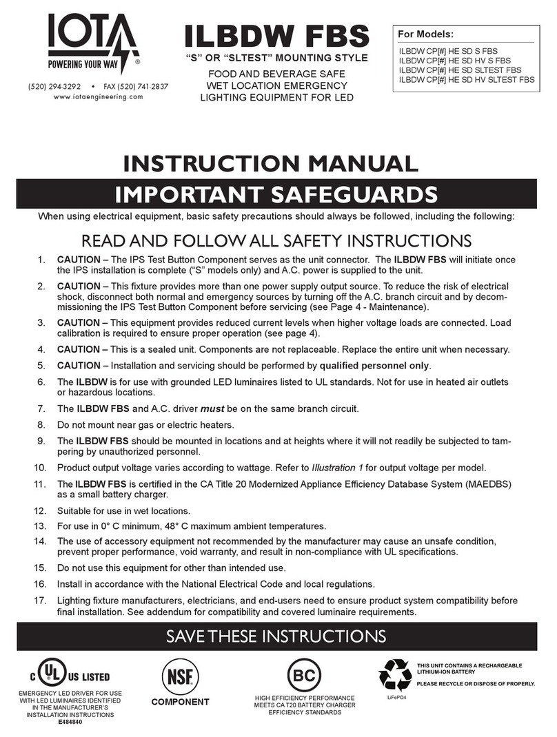
IOTA ILBDW FBS User manual

IOTA

IOTA ILBDW FBS User manual

IOTA ILB CP18 HE CW LP64 User manual

IOTA

IOTA ILB CP18 HE CW LP64 User manual

IOTA ILBLP CP HE SD HV User manual

IOTA

IOTA ILBLP CP HE SD HV User manual

IOTA ILBLP SP HE SD LC CW User manual

IOTA

IOTA ILBLP SP HE SD LC CW User manual

Popular Lighting Equipment manuals by other brands

Lightolier Lytespan 8292WE specification

Lightolier

Lightolier Lytespan 8292WE specification

Clas Ohlson 18-2135 manual

Clas Ohlson

Clas Ohlson 18-2135 manual

Feniex Fusion FN-0116 instruction manual

Feniex

Feniex Fusion FN-0116 instruction manual

Spectroline uVision Series manual

Spectroline

Spectroline uVision Series manual

Hydra Systeme Grille EXTREM installation instructions

Hydra Systeme

Hydra Systeme Grille EXTREM installation instructions

XKGlow XKchrome XK075001-KIT Mounting instructions

XKGlow

XKGlow XKchrome XK075001-KIT Mounting instructions

ACME Theatre Spot 150m user manual

ACME

ACME Theatre Spot 150m user manual

VANQ GLMX Series manual

VANQ

VANQ GLMX Series manual

Beamz BPP210 instruction manual

Beamz

Beamz BPP210 instruction manual

Chauvet Scorpion Dual user manual

Chauvet

Chauvet Scorpion Dual user manual

Home Accents Holiday TY005-2011 Assembly instructions

Home Accents Holiday

Home Accents Holiday TY005-2011 Assembly instructions

Würth 0827 940 16X Translation of the original operating instructions

Würth

Würth 0827 940 16X Translation of the original operating instructions

Merco CONTEMPO SERIES Parts & service manual

Merco

Merco CONTEMPO SERIES Parts & service manual

Protect KN-6120LSMD user manual

Protect

Protect KN-6120LSMD user manual

Schuch nD8611 L02 W Series operating instructions

Schuch

Schuch nD8611 L02 W Series operating instructions

ViSAGE VIS085 Operation manual

ViSAGE

ViSAGE VIS085 Operation manual

Elation DW FRESNEL user manual

Elation

Elation DW FRESNEL user manual

Color imagination LEDZOOM 1915F user manual

Color imagination

Color imagination LEDZOOM 1915F user manual

manuals.online logo
manuals.online logoBrands
  • About & Mission
  • Contact us
  • Privacy Policy
  • Terms and Conditions

Copyright 2025 Manuals.Online. All Rights Reserved.