7
Serie / Series SILVER ITALIANO - INGLESE - FRANCESE - TEDESCO - SPAGNOLO Vers. 04 / 2001 GB
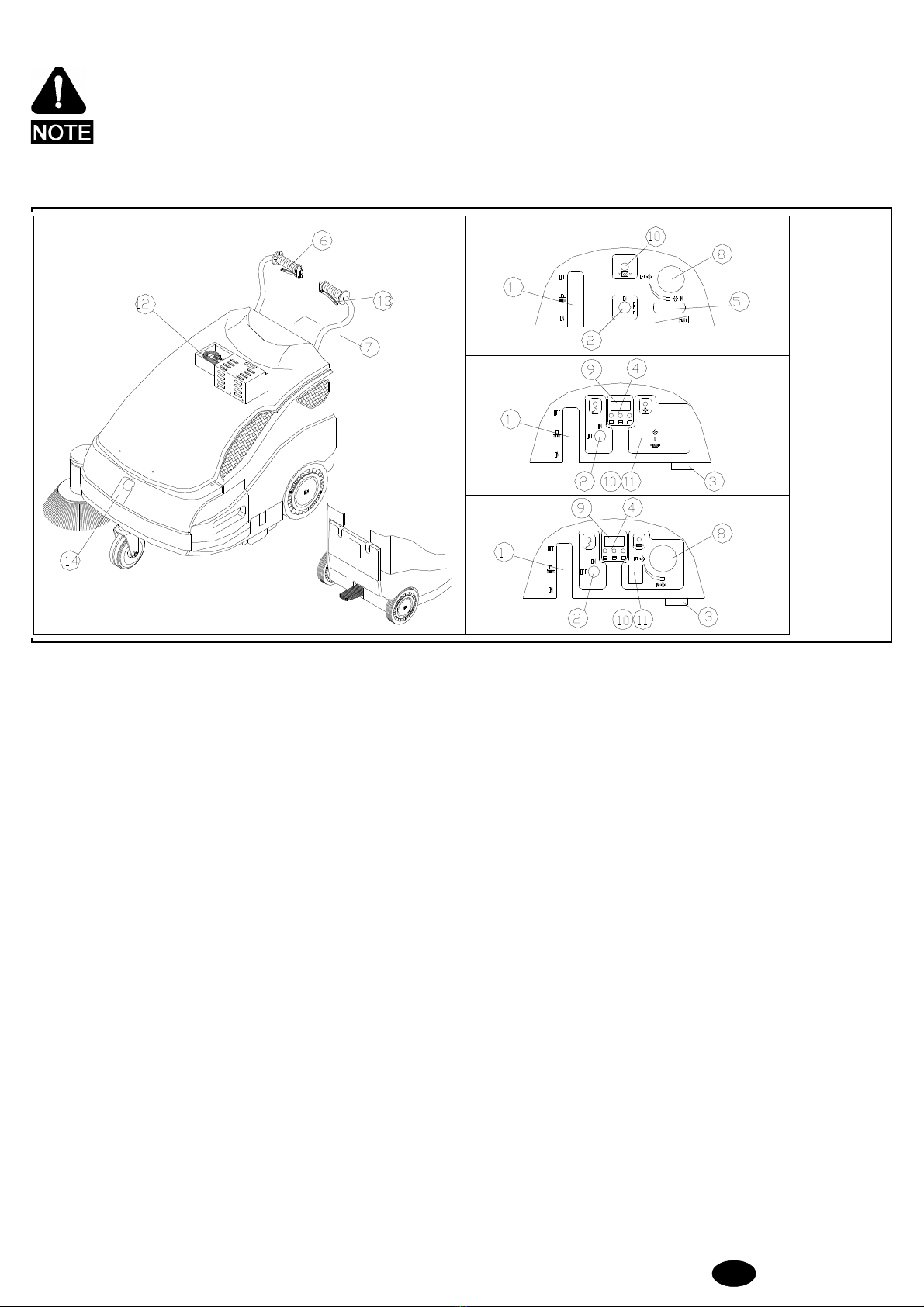
1) Fuel tank cap
2) Choke lever
3) Petrol tap
4) Self-winding ignition cable
5) Air filter
6) Throttle valve lever
7) Start handle
4.1 - STARTING
ATTENTION: the machine must be used by authorised personnel
only. DO NOT leave the machine UNATTENDED
whenit isrunning. Donotuse themachinetosoak up
liquid. Take out the key before leaving the machine.
KEEP THE MACHINE OUT OF CHLIDREN’S
REACH.
4.1.1 - Electrical version
To start the machine carry out the following operations:
- Make sure the side brush pos. 1 Fig. 3. is OFF.
-Turntheswitchpos.2Fig.3ON.Wait10secondsbeforethemachine
sets off.
-Beforethemachine setsworking,check theindicator pos.4Fig.3,to
assess whether the battery is fully charged. If it is not, proceed to
recharge it.
- Pull the traction lever pos. 6 Fig. 3, to start cleaning.
Ifnecessary,operate leverpos.1Fig.3,byturningit ON,tostartthe
side brush. If you have been using the side brush, at the end of your
workremebertoturnitOFF.Switchoffthemachineandremovethe
key from the control panel.
An automatic device will prevent you from using the
machine beyond a certain battery charge limit.
Whenthislimitisreached,themachinewillstopandthebatterymust
be recharged.
4.1.2 - Engine version
- Make sure the side brush pos. 1 Fig. 3, is OFF.
- Ensure that engine has enough petrol and oil.
- Switch accelerator lever pos. 5 Fig. 3, to START.
- Place the key pos. 2 Fig. 3 on ON position.
- Open up fuel tap pos. 3 Fig. 4.
- If the engine is cold, operate the choke lever pos. 2 Fig. 4.
- Operate the start handle pos. 7 Fig. 4.
- As soon as the engine starts running, shut off the choke lever pos. 2
Fig. 4 if it was operated.
- Act on the accelerator pos. 5 Fig. 3, to reach the required speed.
-Attheendofyourwork,ifyouhavebeenusingthesidebrushpos.1Fig.
3turn it OFF. Turn the accelerator lever to START and turn off the
machine with the key pos. 2 Fig. 3. Close up fuel tap pos. 3 Fig. 4.
8) Tank
9) Engine switch
10) Engine name plate
11) Plug
12) Muffler
13) Oil filling cap
14) Oil drain plug Fig. 4 and 5
4.2 - CORRECT OPERATION
Afteryouhavebecomeconversantwiththeoperationsrequiredtostart
themachine,youcanactuallystartusingthesweepertoobtain thebest
results,itis alwayswiseto takeafewprecautions. Thesewillhelp you
to get the best from your machine and reduce damage to a minimum.
In particular:
- do not use the machine to clean up wires,ropes or straps or soak up
water and other liquids.
-Whenusingthemachineon lightbut bulkymaterial(sheets ofpaper,
leaves,etc.), raisethe frontpartof themachinebypressing downthe
handlebar so that the machine can tackle the rubbish.
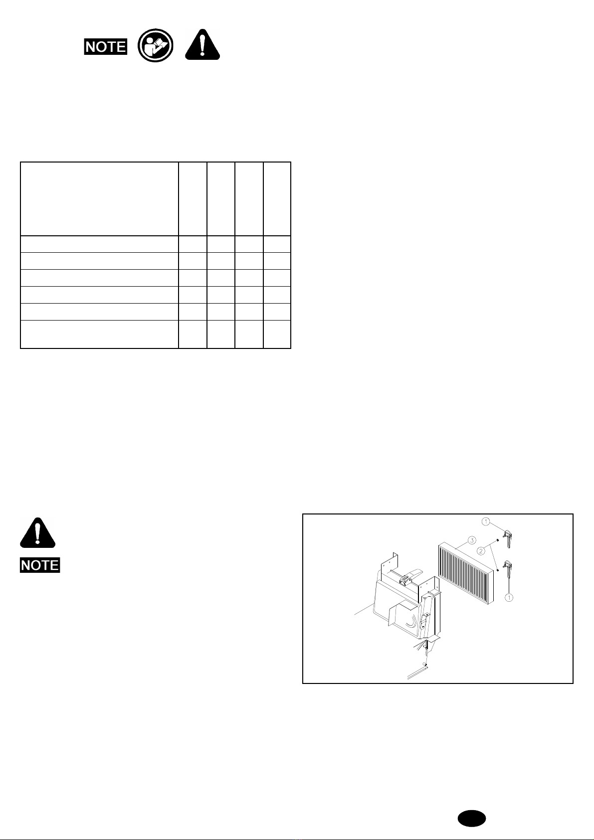
- Operate the filter shaker at the end of your work (see the Panel filter
section).
- Make sure the centre brush is correctly regulated (see the section on
Adjusting the centre brush).
DANGER:petrolishighlyinflammable.Keepyourfuelin
containers designated for the purpose. Top up your fuel
tankONLYwhentheengineisoff.Donotremovethefuel
tankcapwhenthemotorisrunningorhot.Alwaysfillyour
fuel tank in open air or in a sufficiently ventilated area.
Do not smoke during this operation and do not use naked
flames. If you spill fuel during this operation, DO NOT
attempt to start the engine but wait for the vapour to
evaporate.
Always turn off the engine:
- Before leaving the machine unattended;
- Before filling the fuel tank;
- Before carrying out any work on the machine.
4.3 - CLEANING THE WASTE BINS
Before carrying out this operation, make sure all parts are off.
(*) ATTENTION: WASTES MUST BE DISPOSED OF
STRICTLY INACCORDANCE TOTHE
LAW.
4.3.1 - Front bin
- Lift and turn the two bin locks.
- Grasp the handle/s and remove the bin by pulling it upwards.
- Empty the bin (*).
To put the bin back in place:
- Put the bin back in the machine from the top.
- Turn and lower the two locks.
4.3.2 - Rear bin
- Lift and turn the two bin locks.
- Grasp the handle and pull the bin out of the machine.
- Empty the bin (*).
To put the bin back in place:
- Fit the bin back into the machine.
- Turn and press the two locks.
1
2
3
5
4
76
9
8
11
10
14
13
12