manuals.online logo
Brands
  1. Home
  2. •
  3. Brands
  4. •
  5. IPEX
  6. •
  7. Cables And Connectors
  8. •
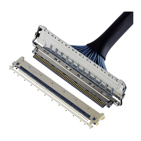
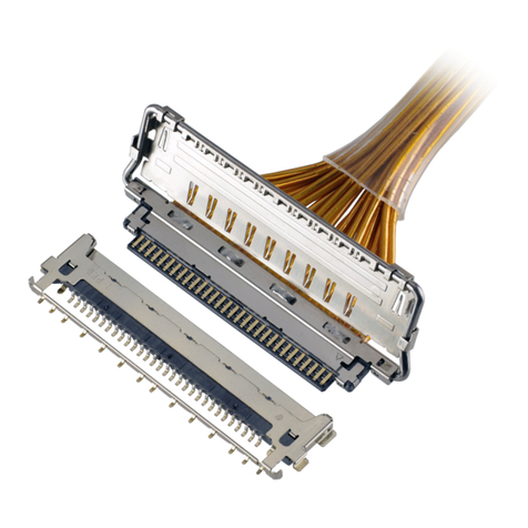
  9. IPEX CABLINE-UA II PLUG User manual

IPEX CABLINE-UA II PLUG User manual

1/ 14
Document No.
ASM
-
09004
Confidential C
I
-
PEX Inc.
QKE
-
DFFDE09
-
04 REV.8
CABLINE®-UA II PLUG
Part No. 20496-#**-##
Assembly Manual
4 S19433 July 8, 2019 S.Yamaguchi T.Kurachi H.Ikari
3 S18098 January 30, 2018 R.Hoshino K.Tanaka M.Takemoto
2 S17547 July 27, 2017 R.Hoshino K.Tanaka M.Takemoto
1 S12558 December 10, 2012
Y.Watanabe K.Narita T.Takano
Rev. ECN Date Prepared by Checked by Approved by
CABLINE
®
-
UA II
P
LUG
Assembly Manual
Document No.
ASM
-
09004
2/ 14
Confidential C
1. 目的 (Purpose)
CABLINE-UA II PLUG における、ケーブルの芯線半田付け手順及び METAL COVER の組み付け手順について明記する。
This manual provides the soldering method of the cable’s center conductor and assembly method of
METAL COVER to CABLINE-UA II PLUG.
2. 適用コネクタ (Applicable connector)
Name : CABLINE-UA II PLUG
Parts No. :
3. パルスヒート条件(Pulse heat condition)
3.1 使用機器等 (Fixtures)
・ パルスヒート (Pulse heater)
・ ヒーターチップ (Heater chip)
26P 32P 40P 50P
板厚 (Thickness)
0.3
-0.05
0mm
幅 (Width) 8.8
-0.03
0mm 10.6
-0.03
0mm
13
.0
-0.03
0mm
16.0
-0.03
0mm
・ 推奨半田バー (Recommended solder bar)
単芯ヤニ無し糸半田を使用
Resin-free solder is used.
Positions Solder size Length
26P
φ0.06
8.7 mm Ref.
32P 10.5 mm Ref.
40P 12.9 mm Ref.
50P 15.9 mm Ref.
Set P/N CABLE ASS’Y 20496-#**-##
Discrete
P/N
HOUSING ASS’Y
20497-#**T-##
METAL COVER 2679-0**-##
Name P/N Manufacturer
リフロヘッド (Reflow head) NA-66 Nippon Avionics Co.,Ltd.
パルスヒート電源 (Pulse heat power supply)
TCW-315
Nippon Avionics Co.,Ltd.
CABLINE
®
-
UA II
P
LUG
Assembly Manual
Document No.
ASM
-
09004
3/ 14
Confidential C
3.2 パルスヒート条件[推奨] (Recommended pulse heat condition)
① アイドリング温度 (Idle temperature) 150 ℃
② 1st ヒート設定温度 (1st heat temperature) 220 ℃
③ 1st 立ち上がり時間 (1st rise time) 0.5 seconds
④ 1st 維持時間 (1st holding time) 3.0 seconds
⑤ 2nd ヒート設定温度 (2nd heat temperature) 340~350 ℃
⑥ 2nd 立ち上がり時間 (2nd rise time) 0.5 seconds
⑦ 2nd 維持時間 (2nd holding time) 3.0 seconds
ヒーターチップ加圧力 (Heater tip Pressure) 12~15 N
※パルスヒート条件の評価は弊社のパルスヒート冶具、装置で確認しております。
パルスヒート冶具形状や装置、環境等の違いにより、最適なパルスヒート条件は変わることが予想されます。
貴社で御使用の際は、充分なパルスヒート条件の検討を行っていただくよう御願い致します。
This pulse heat condition was evaluated and confirmed by our pulse heat jig and instruments. The most
optimum condition may change based on the shapes of pulse heat jig and instruments, the environments,
or other reasons. Therefore, please examine the pulse heat condition adequately in advance of use.
CABLINE
®
-
UA II
P
LUG
Assembly Manual
Document No.
ASM
-
09004
4/ 14
Confidential C
4.作業手順 (Work procedures):
4-1. 芯線の半田付け (Soldering of center-conductor)
①まず適合ケーブルの端末処理形状を下図の様にして下さい。
First, process the cable end as shown below.
【Micro coax cable】
Part No. B C E
20496-#26-##
3.6 8.1 9.0
20496-#32-##
4.5 9.9 10.8
20496-#40-##
5.7 12.3 13.2
20496-#50-##
7.2 15.3 16.2
a
AWG#42 0.075
AWG#44 0.063
AWG#46 0.048
・Cable Dimension Unit: mm
(Unit:mm)
CABLINE
®
-
UA II
P
LUG
Assembly Manual
Document No.
ASM
-
09004
5/ 14
Confidential C
【Discrete cable】
Part No. B C E
20496-#26-##
3.6 8.1 9.0
20496-#32-##
4.5 9.9 10.8
20496-#40-##
5.7 12.3 13.2
20496-#50-##
7.2 15.3 16.2
a
AWG#39 0.102
(Unit:mm)
・Cable Dimension Unit: mm
CABLINE
®
-
UA II
P
LUG
Assembly Manual
Document No.
ASM
-
09004
6/ 14
Confidential C
②コンタクトにフラックスを塗布して下さい。
Apply flux to contact.
Photo 1 Applying flux area
③全コンタクトにフラックスが塗布されたことを確認して下さい。
Please confirm all contacts were applied flux.
Photo 2 After applying flux
※Photo 3 のようにフラックスを塗布し過ぎないで下さい。フラックスの飛散及び
フラックス過多による嵌合部への染み出しの原因となります。
Please do not apply flux too much like Photo 3. It can cause flux splash or leak to the mating area.
Photo 3 Extra flux
※洗浄機等によるフラックスの洗浄は行わないで下さい。フラックスが嵌合部に付着する可能性が有ります。
※Washer must not be used to take flux off because it may cause flux attached to mating area.
Applying flux area
Pass
Fail
CABLINE
®
-
UA II
P
LUG
Assembly Manual
Document No.
ASM
-
09004
7/ 14
Confidential C
④コネクタに半田バー(Solder Bar)をセットする。
Place a solder bar at center of connector (HOUSING ASS’Y).
Fig. 1 Placing solder bar
⑤ケーブルをセットする。
Set the cable.
Fig. 2 Setting cable (MCX)
※Discrete cable を使用する場合は、Jacket の先端と製品のリブの端が合うようにセットして下さい。
When using a discrete cable, set it so that the end of the jacket and the end of the product rib match.
Fig. 3 Setting cable (Discrete)
Cable
Solder Bar
rib
CABLINE
®
-
UA II
P
LUG
Assembly Manual
Document No.
ASM
-
09004
8/ 14
Confidential C
⑥芯線をパルスヒートにて半田付けする。 半田付け状態は、下記 Photo 4, 5 参照。
Solder center conductors with a pulse heater. For soldering condition, see photo 4 and 5.
Photo 4 AWG#44
Photo 5 Expansion part
CABLINE
®
-
UA II
P
LUG
Assembly Manual
Document No.
ASM
-
09004
9/ 14
Confidential C
※極間が短絡または半田が溶け残ってしまった場合は(下記 Photo 7 参照)
ヒーターチップを洗浄して再度パルスヒートにて加熱を行って下さい。
製品にダメージを与える恐れがある為、回数は 1 回だけです。
これで短絡が直らない場合は、NG 箇所のみ半田コテにて手修正して下さい。
In case short circuit occurred or there was any unmelted solder (See photo 7 below),
wash the heater tip and heat again with pulse heater only one time. (Several heating can
damage the product.) If the short circuit can’t be repaired, use the soldering iron and repair it
(Failed point only).
半田コテの条件 (Condition of Soldering iron) : 50 W
半田コテ先温度 (Operating temperature) : 350 ℃~380 ℃
コテ先当て時間 (Application time of soldering iron): 5 秒以内 (Within 5 seconds)
Photo 6 Melted solder Photo 7 Unmelted solder
※2’nd ヒート設定温度と加圧力を上げ過ぎないでください。Housing が溶ける可能性があります。
下記 Photo 9 参照
The setting temperature of 2’nd heat and the pressure shall not be too high.
There is possibility of melting of Housing. Please refer to Photo 9.
Photo 8 Unmelted Housing Photo 9 Melted Housing
Pass
Fail
CABLINE
®
-
UA II
P
LUG
Assembly Manual
Document No.
ASM
-
09004
10 / 14
Confidential C
4-2. METAL COVER 取扱注意事項 (Cautions in treating METAL COVER)
METAL COVER はキャリア付きリール状態にて納品されます。
METAL COVER をキャリアから折り取る手順を明記します。
METAL COVER is delivered in the reel with a carrier.
The following is the method to cut Metal Cover from carrier.
①キャリアを金属用はさみ等を用いて下左写真の Cut Line(緑線)にて切断する。
Cut carrier on the cut line of a lower left picture (green line) by a scissor for metal.
Photo 10 Before cut Photo 11 After cut
②METAL COVER の中心部を持ち、±45°で往復させてノッチ部から切り離します。
もし、切り離れない場合は、この往復動作を繰り返して切り離します。(Photo 12)
切り離し後はノッチ折り取り部にバリ発生なきことを確認してください。(Photo 13)
Hold the center of METAL COVER and bend it 45 degrees back and forth to cut it from Notch.
If it is not separated, bend it again. (Photo 12)
After separated, check if there is no burr around the cut part.(Photo 13)
Photo 12 Cut condition
Carrier
Notch
45
°
45
45
°
45
°
Cut Line
CABLINE
®
-
UA II
P
LUG
Assembly Manual
Document No.
ASM
-
09004
11 / 14
Confidential C
Photo 13 After cut
METAL COVER ノッチ部状態(Detail of Notch)
Photo 14 Bottom side view Photo 15 Upper side view
注意:下写真(赤矢印)の様に無理やり引っ張ったりして切り離すとバリや変形の原因になります。
Caution: By pulling like photo below to cut off by force (Red arrow direction),
burrs and transformation can be caused.
Photo 16 Cut by force (Bad example)
Without burrs
View A
View B
View A
Bottom side view
View B
Upper side
CABLINE
®
-
UA II
P
LUG
Assembly Manual
Document No.
ASM
-
09004
12 / 14
Confidential C
4-3. METAL COVER 組み付け (Assembly of METAL COVER)
①コネクタ上面側から Housing の4箇所のスリットに METAL COVER の爪4箇所を挿入して組み付ける。
Assemble METAL COVER by inserting four nails of Metal Cover into four slits of Housing from the
upper side of the connector.
Fig. 4 Assembly of METAL COVER
※Discrete cable を使用する場合は、METAL COVER を取り付ける前に結線部に絶縁テープを貼りつけて下さい。
When using a discrete cable, please Apply an insulating tape to the connection before assemble METAL COVER
Fig. 5 Assembly of METAL COVER
Slits (4 pcs.)
Metal Cover
Housing
Nails (4 pcs.)
Slits (4 pcs.)
Insulating tape
20496-#26-## 3.80
20496-#32-## 4.70
20496-#40-## 5.90
20496-#50-## 7.40
(mm) L h t
(thickness)
0.08MAX.0.72
HOUSING 及びケーブルのジャケットには掛からないようにお願いします。
METAL COVER の浮きが発生する可能性があります。
Please do not hang on HOUSING and cable jackets.
It might cause the METAL
COVER float.
CABLINE
®
-
UA II
P
LUG
Assembly Manual
Document No.
ASM
-
09004
13 / 14
Confidential C
③METAL COVER が正常に組み立てられているか確認する。
METAL COVER が HOUSING に挿入されているか。(Fig. 4 ★部 及び Photo 17 参照)
Confirm whether METAL COVER is assembled properly or not.
Confirm whether METAL COVER is inserted into Housing. (See Fig. 4 ★ point and Photo 17)
【チェックポイント】
(1) METAL COVER の Housing 上面からの浮き量は 0.05 mm Max.
(2) METAL COVER の 4 箇所の爪がハウジングの4箇所のスリットに確実にはまっていること。
Check point:
(1)The amount of floats from housing surface :0.05 mm Max.
(2)Four nails of METAL COVER have fitted into four slits of housing certainly.
Fig. 6 The assembly confirmation of METAL COVER
Check points (2) detail (Comparison of Pass and Fail)
Pass Fail
Photo 17 View A
※爪がスリットにはまっているかコネクタ底面から確認のこと。
From the connector bottom side, confirm whether the nail has fitted into the slit or not.
★
point
0.05 mm Max.
View A
CABLINE
®
-
UA II
P
LUG
Assembly Manual
Document No.
ASM
-
09004
14 / 14
Confidential C
④Metal Cover の表側 3 箇所を Ground Bar を半田コテにて半田付けする。(Fig. 5 ◆部)
半田の高さ(半田量)の限度は Fig. 6 を参照。
半田コテの条件は、8 頁参照。
Solder holes of METAL COVER 3 positions and Ground Bar with the soldering iron. (Fig. 5 ◆ points)
Refer to Fig. 6 for a limit of the solder height.
For conditions of soldering iron, refer to sheet 8.
Fig. 7 Soldering of METAL COVER and Ground Bar
Fig. 8 Soldering
◆points
Soldering
0.05 Max.
1.14
1.21 Max.

This manual suits for next models

16

Other IPEX Cables And Connectors manuals
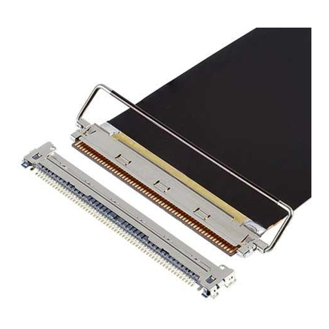
IPEX MP-A 03 User manual

IPEX

IPEX MP-A 03 User manual

IPEX MINIFLEX 175-ST User manual

IPEX

IPEX MINIFLEX 175-ST User manual
IPEX NOVASTACK-B User manual

IPEX

IPEX NOVASTACK-B User manual

IPEX CABLINE-UM PLUG User manual

IPEX

IPEX CABLINE-UM PLUG User manual

IPEX CABLINE-UM User manual

IPEX

IPEX CABLINE-UM User manual
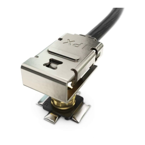
IPEX CABLINE-UX II PLUG User manual

IPEX

IPEX CABLINE-UX II PLUG User manual

IPEX CABLINE-VS IIF User manual

IPEX

IPEX CABLINE-VS IIF User manual

IPEX CABLINE-CX II PLUG Without Cover User manual

IPEX

IPEX CABLINE-CX II PLUG Without Cover User manual

IPEX CABLINE-VSF User manual

IPEX

IPEX CABLINE-VSF User manual

IPEX MHF-A User manual

IPEX

IPEX MHF-A User manual

IPEX ISH VW User manual

IPEX

IPEX ISH VW User manual

IPEX MHF I User manual

IPEX

IPEX MHF I User manual
IPEX CABLINE-VSF User manual

IPEX

IPEX CABLINE-VSF User manual

IPEX ISH User manual

IPEX

IPEX ISH User manual
IPEX NOVASTACK 35-HDN User manual

IPEX

IPEX NOVASTACK 35-HDN User manual

IPEX MINIFLEX 2-BF LK User manual

IPEX

IPEX MINIFLEX 2-BF LK User manual

IPEX ISH User manual

IPEX

IPEX ISH User manual
IPEX CABLINE-UY User manual

IPEX

IPEX CABLINE-UY User manual

IPEX CABLINE-CA II PLUS User manual

IPEX

IPEX CABLINE-CA II PLUS User manual

IPEX MINIFLEX 4-ST User manual

IPEX

IPEX MINIFLEX 4-ST User manual

IPEX CABLINE-CA IIF User manual

IPEX

IPEX CABLINE-CA IIF User manual

IPEX MP-A01 User manual

IPEX

IPEX MP-A01 User manual
IPEX CABLINE-CBL PLUG User manual

IPEX

IPEX CABLINE-CBL PLUG User manual

IPEX CABLINE-UY 20857-0 T-0 Series User manual
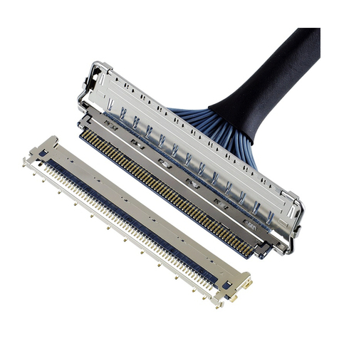
IPEX

IPEX CABLINE-UY 20857-0 T-0 Series User manual

Popular Cables And Connectors manuals by other brands

Siemens 3RK1911-2B 0 Series operating instructions

Siemens

Siemens 3RK1911-2B 0 Series operating instructions

Accell K078C-008B manual

Accell

Accell K078C-008B manual

Bosch CPR 0001 A Product description/Installation manual

Bosch

Bosch CPR 0001 A Product description/Installation manual

JST CN-SAP1190 manual

JST

JST CN-SAP1190 manual

Siemens 3VA9373-0JJ24 operating instructions

Siemens

Siemens 3VA9373-0JJ24 operating instructions

Rocstor Y10C132-B1 Instruction guide

Rocstor

Rocstor Y10C132-B1 Instruction guide

LINK-MI LM-SPH02-100 operating instructions

LINK-MI

LINK-MI LM-SPH02-100 operating instructions

DH Instruments PPC - TEST PORT CONNECTIONS KIT installation instructions

DH Instruments

DH Instruments PPC - TEST PORT CONNECTIONS KIT installation instructions

Factor HD-1x2-4K user manual

Factor

Factor HD-1x2-4K user manual

Honeywell GSMX-AUDIO Cable Routing Instructions

Honeywell

Honeywell GSMX-AUDIO Cable Routing Instructions

Stihl Smart Connector instruction manual

Stihl

Stihl Smart Connector instruction manual

knapp KLICK instruction manual

knapp

knapp KLICK instruction manual

ProLights SPLITTER4WRK user manual

ProLights

ProLights SPLITTER4WRK user manual

Condux 8 User's guide & safety manual

Condux

Condux 8 User's guide & safety manual

LINK-MI LM-SP20 operating instructions

LINK-MI

LINK-MI LM-SP20 operating instructions

Philips SWV3232W/10 user manual

Philips

Philips SWV3232W/10 user manual

Staubli PV In-Line-Fuse Installation and operation manual

Staubli

Staubli PV In-Line-Fuse Installation and operation manual

Philips SWA2051T Specifications

Philips

Philips SWA2051T Specifications

manuals.online logo
manuals.online logoBrands
  • About & Mission
  • Contact us
  • Privacy Policy
  • Terms and Conditions

Copyright 2025 Manuals.Online. All Rights Reserved.