IPEX ISH User manual

1/ 22
Document No.HDM-0006
Confidential C I-PEX Inc. QKE-DFFDE09-03 REV.8
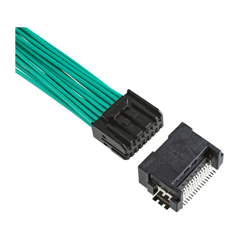
ISH® INLINE CONNECTOR
Instruction Manual
3
RS0743
September 18, 2020
H.Naoi
J.Tateishi
E.Kawabe
2
RS0550
August 18, 2018
S.Tanaka
S.Tono
T.Osuga
1
RS0511
July 10, 2018
H.Naoi
T.Osuga
E.Kawabe
0
RS0264
December 10, 2015
K.Hanaki
J.Mukunoki
T.Endo
Rev.
ECN
Date
Prepared by
Checked by
Approved by

ISH INLINE CONNECTOR Instruction Manual
Document No.
HDM-0006
2/ 22
Confidential C
Contents
1. Purpose
2. Applicable items
3. Crimping procedure
4. Terminal insertion
5. Secondary lock part installation
6. How to release Secondary lock part
7. How to release terminals
8. Mating of connector
9. Unmating of connector
10.Handling of Product
11.Storage of housings and terminals
12.Jig
13.Other notes
14.Contact
・・・・・ Sheet 3
・・・・・ Sheet 3
・・・・・ Sheet 4
・・・・・ Sheet 13
・・・・・ Sheet 14
・・・・・ Sheet 16
・・・・・ Sheet 17
・・・・・ Sheet 19
・・・・・ Sheet 20
・・・・・ Sheet 21
・・・・・ Sheet 22
・・・・・ Sheet 22
・・・・・ Sheet 22
・・・・・ Sheet 22

ISH INLINE CONNECTOR Instruction Manual
Document No.
HDM-0006
3/ 22
Confidential C
1.Purpose
The Manual explains the handling of ISH INLINE CONNECTOR.
For female connector, refer to the Handling Manual 【ISH CONNECTOR No.HDM-0002】.
2.Applicable items
The Manual is applicable to the items listed below.
Name
Part No.
Image
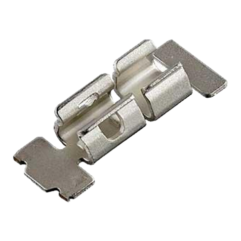
MALE TERMINAL
VT002-012
MALE CONNECTOR
FEMALE CONNECTOR

ISH INLINE CONNECTOR Instruction Manual
Document No.
HDM-0006
4/ 22
Confidential C
3.Crimping procedure
3-1.Applicable wires
3-2.Wire strip length
①Strip the insulation off by 3.0±0.1mm (see Fig.1)
②Check to see that there is no damage to the conductors or insulation, cut off conductors, short conductors
and deformed conductors as shown in Fig. 2.
Do not use wires with damaged conductors, cut off conductors, short conductors and deformed conductors.
Using faulty wires may cause crimping problems.
Part No. Applicable Wire
VT002-012
wire size:0.3mm2・0.5mm2
Insulation outer diameter:Φ1.60mm MAX.
3.0±0.1mm
Conductors
Insulation
Fig 2. Stripped wires (unacceptable examples)
Fig 1.Wire strip
Cut off conductors
(defect)
Deformed conductors
(defect)
Condition
Image
Good
Damaged conductors
(defect)

ISH INLINE CONNECTOR Instruction Manual
Document No.
HDM-0006
5/ 22
Confidential C
3-3.Terminal part names
3-4. Crimping requirements
(1) Crimp dimension
Crimped female terminals must satisfy the crimp dimension specified in Table 1.
※Crimp dimensions may be different depending on conductor construction of the wire.
Please contact our Sales Department shown in 14(sheet 22) about wire used, then we will verify it and
notify you the appropriate crimp dimensions.
Fig 3. Terminal part names
Table 1. Crimp dimension
Insulation barrel Crimp Height
0.95±0.05 (※)
Part No.
Wire Size
Insulation
Outer Diameter
Wire barrel Crimp Height
Wire barrel Crimp Width
1.8±0.05
Insulation barrel Crimp Width
VT002-012
0.3mm2
Φ1.60mm MAX.
0.9±0.05 (※)
1.4±0.04
1.6+0.1/-0.05
1.55±0.05
0.5mm2

ISH INLINE CONNECTOR Instruction Manual
Document No.
HDM-0006
6/ 22
Confidential C
Measuring method for crimp dimension is described below.
Use the micrometer shown in Fig.4 for measurement of each part.
Fig 4. Micrometer
(1)-1. Measuring method for wire barrel crimp height is described below.
To measure the wire barrel crimp height, pinch the top of the wire barrel (winding side) and the bottom of
the wire barrel with a micrometer. (see Fig.5)
Secure terminals firmly to obtain accurate measurement.
Do not pinch the bell mouth. The wire barrel crimp height can not measure accurately.
(1)-2. Measuring method for insulation barrel crimp height is described below.
To measure the insulation barrel crimp height, pinch the top of the insulation barrel (winding side) and the bottom of
the insulation barrel with a micrometer. (see Fig.6)
Secure terminals firmly to obtain accurate measurement.
Fig 5.Wire barrel Crimp height measurement
Fig 6. Insulation barrel Crimp height measurement
Section
Section
Do not pinch the bellmouth.
Micrometer
Micrometer

ISH INLINE CONNECTOR Instruction Manual
Document No.
HDM-0006
7/ 22
Confidential C
(1)-3. Measuring method for wire barrel crimp width is described below.
To measure the wire barrel crimp width, pinch the side of the wire barrel with a micrometer. (see Fig.7)
Secure terminals firmly to obtain accurate measurement.
Fig 7. Wire barrel Crimp width measurement
(1)-4. Measuring method for insulation barrel crimp width is described below.
To measure the insulation barrel crimp width, pinch the side of the insulation barrel with a micrometer. (see Fig.8)
Secure terminals firmly to obtain accurate measurement.
Fig 8. Insulation barrel crimp width measurement
Section
Section
Micrometer
Micrometer

ISH INLINE CONNECTOR Instruction Manual
Document No.
HDM-0006
8/ 22
Confidential C
(2) Bottom burrs
Burrs produced during crimping process must not extend beyond the bottom surface. (see Fig.9)
(3) Bellmouth,excess conductors and cut-off tab
Bellmouth,excess conductors and cut-off tab must satisfy the dimensions shown in Fig. 10 and Table 2.
Fig.10. Bellmouth, excess conductors and cut-off tab
No extension
Extension
Bottom surface of terminal
Bottom burrs
【Good】
【No good】
Fig 9. Bottom burrs

ISH INLINE CONNECTOR Instruction Manual
Document No.
HDM-0006
9/ 22
Confidential C
(4) Unaligned wire barrel ends
Unaligned wire barrel ends is 0.1mm MAX..(Fig.11)
※If wire barrel ends are not aligned, resulting in different dimension of excess conductors or
bellmouth between the sides,dimensions must be measured on larger side and be satisfied.
(In the case shown in Fig.12, measure excess conductors:[a],bellmouth:[b].)
(5) Rolling
Rolling is 3°MAX. from the wire barrel (baseline).(see Fig.13)
Fig13. Rolling
Fig 12. Example of unaligned wire barrel ends
Fig 11. Unaligned wire barrel ends
Example①
Example②

ISH INLINE CONNECTOR Instruction Manual
Document No.
HDM-0006
10 / 22
Confidential C
(6) Terminal twist
Terminal twist is 1.2° MAX. from the wire barrel (baseline). (see Fig. 14)
(7) Bend up and Bend down
Bend up is 1.10mm MAX., and no Bend down respectively, the hight from the wire barrel(baseline) to
the terminal box(measurement point). (see Fig. 15~16)
Fig 15. Bend up
Fig 16. Bend down
Fig 14. Terminal twist
No bend down

ISH INLINE CONNECTOR Instruction Manual
Document No.
HDM-0006
11 / 22
Confidential C
3-5. Defective criteria
Terminals with the following conditions are deemed defective.
(1) No rear bellmouth
Rear bellmouth is not formed. (see Fig.17)
(2)Insufficient conductors insertion
Conductors are insufficiently inserted into the wire barrel. (see Fig.18)
(3)Excessive conductors out
Excess conductors protrude from the wire barrel and does not satisfy the dimension in fig.10 of sheet 8. (Fig.19)
(4)Incomplete conductors crimping
Conductors are not crimped inside the wire barrel, or within the female terminal. (see Fig.20)
Fig 17. No rear bellmouth
Fig 18. Insufficient conductors insertion
Fig 20. Incomplete conductors crimping
Fig 19 Excessive conductors out

ISH INLINE CONNECTOR Instruction Manual
Document No.
HDM-0006
12 / 22
Confidential C
(5)Incomplete insulation crimping
Strip length is too short and insulation is crimped inside the wire barrel (see Fig.21).
Strip length is too long and insulation does not fit completely inside the insulation barrel (see Fig.22)
(6)Torn insulation
Insulation is torn by insulation barrel. (see Fig.23)
Fig 22.Strip too long
Fig 21.Strip too short
Fig 23. Torn insulation
Torn insulation caused
by insulation crimping.

ISH INLINE CONNECTOR Instruction Manual
Document No.
HDM-0006
13 / 22
Confidential C
4.Terminal insertion
①Ensure that the terminal is crimped correctly and there is no damage, deform or dirt present.
②Hold the wire to insert the terminal as shown in Fig.24.
③Insert the terminal into the corresponding corehole of the housing, as deeply as possible, in the orientation as shown in Fig. 24.
④Once the terminal is inserted, ensure that the terminal retention is fastened by pulling the wire lightly towards you.
⑤Terminals won’t fit into the housing coreholes, if inserted in the wrong orientation (see Fig. 25).
Notes:
①Terminals must be inserted in the orientation instructed. Forcibly inserting terminals in any other orientation may result in damage or
deformation.Furthermore,if the terminals are inserted with incorrect orientation, terminal key prevents insertion into coreholes. (see Fig.25)
②Once the terminal is inserted, do not apply excessive pulling force to the wire.
Fig 24. Terminal insertion direction
Fig 25. Incorrect terminal insertion
Hold the wire
Polarization key (underside)
Keys prevent incorrect insertion

ISH INLINE CONNECTOR Instruction Manual
Document No.
HDM-0006
14 / 22
Confidential C
5. Secondary lock installation
①After terminal insertion is complete, close the secondary lock part.
You will hear audible click when the secondary lock part is engaged properly.
(The secondary lock part has two engaging portions. Press down to make sure both portions are engaged)
②Check that the secondary lock part is closed in compretely, i.e. aligned with the bottom surface of the housing.
When the secondary lock part cannot be closed in completely, do not close forcefully. Check that the terminals
are inserted correctly and sufficiently,and repeat the insertion procedure in 4. Insert all the
terminals properly, and push the secondary lock part until audible click is heard.
③When terminal(s) is/are insufficiently inserted as shown in Fig.27, the Secondary lock part cannot be closed.
Insert the terminal(s) completely, and close the secondary lock part again.
Close
Engaging portion
Engaging portion
Fig 26. Installation of the secondary lock part
Before
After
The secondary lock part cannot be closed
Fig.27. Insufficient the secondary lock part engagement
Secondary lock part

ISH INLINE CONNECTOR Instruction Manual
Document No.
HDM-0006
15 / 22
Confidential C
④Do not use fingertips to install secondary lock parts as shown in Fig. 28.
Notes:
①Initial position of the secondary lock part may be different.This does not affect the quality of the product.
OK
OK
No good
Good
Good:Use fingerpad
⇒Prevent damage by fingernails
No good:Do not use fingertip
⇒Possible damage by fingernails (see Fig.29)
Fig.28. Precautions for the secondary lock part installation
Fig.29. Example of damage on the secondary lock part
Initial position

ISH INLINE CONNECTOR Instruction Manual
Document No.
HDM-0006
16 / 22
Confidential C
6.How to release the secondary lock part
①Place the releasing jig into the secondary lock part taper situated at the bottom of the housing, and move the
jig to the direction shown in Fig. 30to release the secondary lock part (release one side at a time).
Secondary lock part releasing jig: Part No. AP-0004-08-002
Notes
①Do not insert the releasing jig into any other incorrect place.
②Check for any deformation or damage on both of the secondary lock part and the housing after releasing the secondary lock part, before
continuing any operation.
③If there is any damage or deformation, do not use the damaged item.
Replace the item with a new one.
④Only use the secondary lock part releasing jig specified.
⑤Care must be taken when handling the secondary lock part releasing jig (it has very sharp edge)
⑥Care must be taken not to damage edge of the jig (e.g. from dropping, etc.)
Fig 30.How to release the secondary lock part
Releasing jig aperture
Place flat surface inside
Direction of release
Secondary lock part releasing jig

ISH INLINE CONNECTOR Instruction Manual
Document No.
HDM-0006
17 / 22
Confidential C
7. How to release terminals
(Terminal releasing Jig dimentions see Fig32.)
①Ensure that the secondary lock part have been removed.
②Hold the wire and push in the terminal lightly. Place the terminal releasing jig into the releasing apertures of the housing (see Figs. 31).
③Push the releasing jig fully into the lance, then lever up the lance as shown in Fig.35.
Keep the jig in the place and pull the terminal out by holding the wire.
Take caution not to touch the terminals with the jig.
④If there is any difficulty in pulling out the terminal, do not pull it forcefully. Check that the jig is in the correct place, that it is pushed fully in, etc.
and repeat the procedures ①to ③.
Terminal releasing JIG: Part No. AP0004-05-002
Fig 31. Female housing and Direction of release
Fig32. Dimensions : Terminal releasing Jig
Terminal releasing jig
Place flat surface of the jig outside.
DETAIL A
DETAIL B
Terminal releasing jig aperture

ISH INLINE CONNECTOR Instruction Manual
Document No.
HDM-0006
18 / 22
Confidential C
Notes
①Do not pry with the releasing jig or terminals during operation. Check for any deformation or damage on the terminals and the housing after
releasing the terminals.
②Do not continue applying force once the lance has reached the ceiling. This could cause deformation to the ceiling, damage or deformation to
the releasing jig or terminals. Take sufficient care when handling.
(see Fig.36)
③If there is any damage or deformation on the terminal or the housing, do not use the damaged item.
Replace the item with a new one.
④Only use the terminal releasing jig specified.
⑤Care must be taken not to damage edge of the jig (e.g. from dropping, etc.)
Fig34.Correct orientation of the releasing jig and the housing lance
Fig 35.Terminal releasing jig in operation
Fig.36. Deformed ceiling, Damaged releasing jig
Terminal releasing jig
Direction of release
Pivot of releasing jig
Terminal releasing jig
Deformed ceiling
Damaged releasing jig
Excessive rotation

ISH INLINE CONNECTOR Instruction Manual
Document No.
HDM-0006
19 / 22
Confidential C
8. Mating of connector
①Once the secondary lock part have been installed, push the connector in the direction of mating until the connector makes an audible click (see
Fig. 37).
While mating the female connector,please do not touch the lock arm to prevent insufficient mating.
②After that, pull the female connector lightly to check that the female connector is locked.
Notes
①Only plug the connector in the direction instructed above. Do not forcefully plug in any orientation shown in Fig.38.
Doing so may cause damage or deformation to connectors.
②If there is any damage or deformation, do not use the damaged item.
Replace the item with a new one.
Fig37.Direction of mating
Fig 38. Mating orientations (not advisable)
Direction of mating
Lock arm

ISH INLINE CONNECTOR Instruction Manual
Document No.
HDM-0006
20 / 22
Confidential C
9. Unmating of connector
①Hold the female connector and push it in lightly.
②While holding the female connector in, press down fully on the end of the arm (see Fig. 39).
③Keep pressing the lock down, and pull out the female connector.
Notes
①Do not pull out the female connector without the lock arm fully pressed down.
It may cause damage or deformation to the connector.
②Hold and pull the female connector (not the harness), when disengaging the connectors.
③If there is any damage or deformation, do not use the damaged item.
Replace the item with a new one.
④Pressing down the front of the arm may not release the lock fully (see Fig. 40)
Fig39. Lock arm
③Pull out female connector
Direction of pressing
②Press down on the edge
Push point
①Push in lightly
When the lock arm is pressed on the front part,
center of the lock is bent.
Fig40. Mechanism of the lock
Press vertically with a thumb
Good
No good
When the lock arm is pressed on the end,
back portion of the lock is bent.
Other manuals for ISH
1
Table of contents
Other IPEX Cables And Connectors manuals
IPEX
IPEX MHF 7S User manual

IPEX
IPEX MHF-A User manual

IPEX
IPEX CABLINE-UM User manual

IPEX
IPEX CABLINE-CAL PLUG User manual

IPEX
IPEX CABLINE-CX II With Cover User manual

IPEX
IPEX CABLINE-VS IIF User manual

IPEX
IPEX MP-A01 User manual

IPEX
IPEX ISH20P User manual
IPEX
IPEX ISH Series User manual

IPEX
IPEX NOVASTACK-B User manual

IPEX
IPEX ISH User manual

IPEX
IPEX CABLINE-CBL PLUG User manual

IPEX
IPEX AP-10 User manual

IPEX
IPEX CABLINE-UY User manual
IPEX
IPEX CABLINE-VS User manual
IPEX
IPEX CABLINE-CAF User manual

IPEX
IPEX FPL II User manual

IPEX
IPEX MINIFLEX 4-ST User manual

IPEX
IPEX CABLINE-CA PLUG User manual

IPEX
IPEX EVAFLEX 5-HD User manual