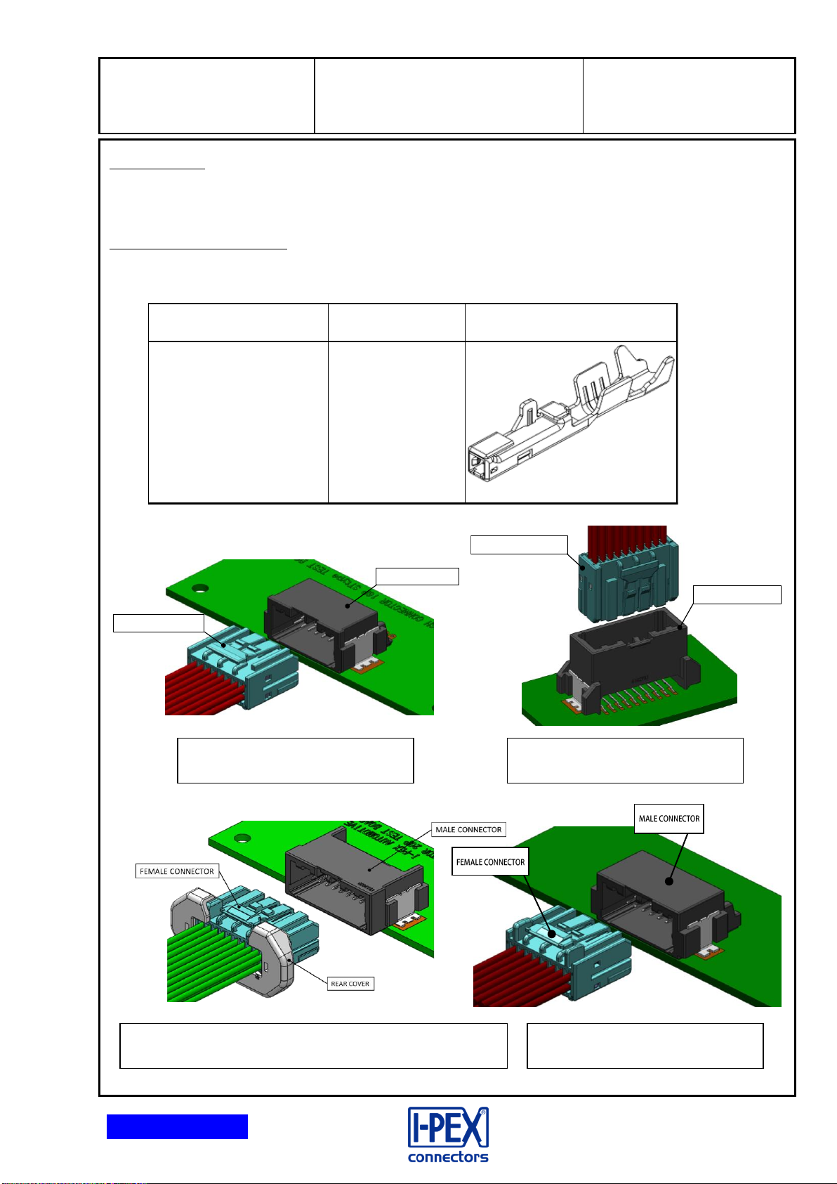
IPEX ISH User manual
Other IPEX Cables And Connectors manuals

IPEX
IPEX MINIFLEX 5-BF II User manual

IPEX
IPEX NOVASTACK 35-HDN User manual

IPEX
IPEX CABLINE-UY User manual

IPEX
IPEX CABLINE-CA PLUG User manual

IPEX
IPEX CABLINE-CA IIF User manual

IPEX
IPEX CABLINE-CAL PLUG User manual

IPEX
IPEX CABLINE-CX II With Cover User manual

IPEX
IPEX CABLINE-CBL PLUG User manual

IPEX
IPEX AP-10 User manual

IPEX
IPEX CABLINE-UM PLUG User manual

IPEX
IPEX MINIFLEX 2-BF User manual

IPEX
IPEX CABLINE-VSF User manual

IPEX
IPEX MHF-A User manual

IPEX
IPEX EVAFLEX 5-HD User manual

IPEX
IPEX CABLINE-UA II PLUG User manual

IPEX
IPEX CABLINE-CAF User manual

IPEX
IPEX ISH Series User manual

IPEX
IPEX MINIFLEX 175-ST User manual

IPEX
IPEX EVAFLEX 5-SE-GHT User manual

IPEX
IPEX CABLINE-VSF User manual