manuals.online logo
Brands
  1. Home
  2. •
  3. Brands
  4. •
  5. IPEX
  6. •
  7. Cables And Connectors
  8. •
  9. IPEX CABLINE-CAF User manual

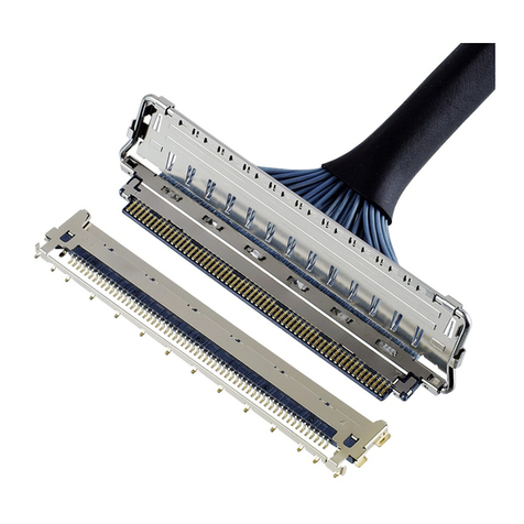
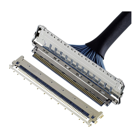
IPEX CABLINE-CAF User manual

1/ 13
Document No.
HIM
-
1
8016
Confidential C
I
-
PEX Inc. QKE
-
DFFDE09
-
03 REV.8
CABLINE®-CAF
Part No.3437-0**1 (SHELL Only), 20858-0**T-01 (SHELL ASS’Y)
Instruction Manual
2 S20346 July 10, 2020 R.Fukuda M.Muro Y.Shimada
1 S19185 March 28, 2019 K.Hara T.Masunaga Y.Shimada
0 S18460 July 27, 2018 Y.Sasa T.Masunaga H.Ikari
Rev. ECN Date Prepared by Checked by Approved by
CABLINE
-
CAF
Instruction Manual
Document No.
HIM
-
1
8016
2/ 13
Confidential C
弊社、CABLINE-CAF CONN.の取り扱いに際して、本コネクタを安全に御使用頂くことを目的とし、
コネクタの挿入・抜去の手順及び注意点を記述致します。
This manual outlines how to correctly mate and unmate CABLINE-CAF connectors, as well as precautions for proper handling of the product.
【対象コネクタ名称・型番】 / Connector Name, Part number
◆FPC 側コネクタ (FPC side connector)
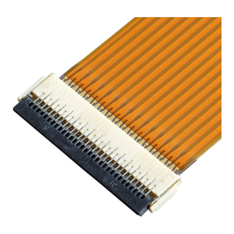
名称 / Product Name :CABLINE-CAF PLUG
型番 / Part No. :20858-0**T-01 ・・・・・・・ SHELL ASS’Y (With LOCK BAR)
3437-0**1 ・・・・・・・ SHELL (Without LOCK BAR)
◆基板側コネクタ (PCB side connector)
名称 / Product Name :CABLINE-CA RECEPTACLE
型番 / Part No. :20525-※**E-※※※
“**”には各芯数番号が入ります。
“**”: Connector pin count.
“※”はバリエーションになります。詳細は図面を参照願います。
“※”: Connector variation type. Refer to the drawing for the details.
【コネクタ各部名称】 Labelled diagram of the connector
図1(Fig. 1) Connector parts names
FPC 側コネクタ
PLUG
基板側コネクタ
Receptacle
I-PEX MARK
嵌合基準マーク
Datum pin mark
LOCK BAR
嵌合方向
Mating direction
CABLINE
-
CAF
Instruction Manual
Document No.
HIM
-
1
8016
3/ 13
Confidential C
【コネクタ挿入手順 / How to mate connectors】
1.FPC 側コネクタのセット方法(Direction to mate.)
図2のように、基板側コネクタの基準 pin にFPC 側コネクタの基準 pin がくるように、セットします。
As shown in Fig.2, please set plug so that the datum pin mark of the plug connector and the receptacle connector are matched.
図2(Fig.2)
2.嵌合方法(How to mate.)
図3のように、FPC を水平に押し、ロック穴にロックが掛かると、嵌合完了となります。
As shown in Fig.3, push FPC horizontally until it is locked.
図3(Fig.3)
SHELL (LOCK BAR 無し)の場合 / For the connector SHELL(Without LOCK BAR).
FPC を水平に挿入する
Insert FPC to the connector horizontally.
ロックが掛かっている事を確認
Check if it is locked.
FPC 側コネクタ基準 pin
Datum pin of plug connector.
ロックが掛かっている事を確認
Check if it is locked.
基板側コネクタ基準 pin
Datum pin of receptacle connector.
隙間がないか確認
Confirm whether there is space.
⇒
Rece shell
I-PEX MARK
Plug shell
Plug shell とRece shell がオーバーラップ
している事を確認
Check the overlap of Plug shell and Rece shell.
CABLINE
-
CAF
Instruction Manual
Document No.
HIM
-
1
8016
4/ 13
Confidential C
注意事項 / Cautions.
片側ずつ押すと、隙間が発生する恐れが有ります。(図 4)
When you push one end it might cause half mating. (Fig.4)
図4(Fig.4)
隙間発生 NG 状態
There is gap. NG
片側挿入 1
Push the one side.
片側挿入 2
Push the one side.
CABLINE
-
CAF
Instruction Manual
Document No.
HIM
-
1
8016
5/ 13
Confidential C
SHELL ASS’Y(LOCK BAR 付)の場合 / For the connector SHELL ASS’Y(With LOCK BAR).
1.FPC 側コネクタのセット方法 (How to place plug connector)
図5のように基板側コネクタの基準 pin にFPC 側コネクタの基準 pin がくるようにセットする。
Place the plug and receptacle so that their datum pin marks are aligned. [Fig. 5]
2.嵌合方法 (How to mate connectors.)
①:図 6のように仮挿し状態時に、LOCK BAR を基板側コネクタ側にロックしない程度に回転させ、FPC を水平に押す。
そして、突き当て面に隙間がないか確認する。
Insert plug into receptacle. Slightly rotate the lock bar toward receptacle but do not lock it yet.
Push the FPC horizontally until it is fully inserted. Make sure that connectors are completely mated. [Fig. 6]
②:図 7のように嵌合完了後、LOCK BAR を基板側に押し込み、基板側コネクタの SHELL とロックさせる。
Push down the lock bar to hook receptacle shell to lock connectors. [Fig. 7]
基板側コネクタ基準 pin
Datum pin mark on receptacle connector
FPC 側コネクタ基準 pin
Datum pin mark on plug connector
I-PEX mark
図5 (Fig. 5) Aligned datum pin marks on plug and receptacle
図6(Fig. 6) Inserting FPC
図7(Fig. 7) Locking lock bar
CABLINE
-
CAF
Instruction Manual
Document No.
HIM
-
1
8016
6/ 13
Confidential C
※嵌合後確認内容 (Mating check points)
※注意 (Cautions)
Ⅰ:図 9のように挿入時に LOCK BAR を押しながら挿入すると、LOCK BAR が変形したり、
回転軸がコネクタから抜ける恐れがありますので、行わないでください。
Do not push the lock bar while inserting connector, as this may deform the lock bar or rotation axis may fall off from the connector.
Make sure to hold FPC for proper insertion. [Fig. 9]
Ⅱ:図 10 のように片側ずつ押すと、隙間が発生する恐れが有ります。
Do not push one side of the plug shell or the gap may cause improper mating. [Fig. 10]
ロックが掛かっている事を確認
Make sure that locks are hooked
隙間がないか確認
No gap
図8Fig. 8 Checking points of the proper mating
図10(Fig. 10) Improper way to push plug
片側挿入 1
Do not push one end
隙間発生 NG 状態
Gap indicates bad mating
片側挿入 2
Do not push the other end
図9(Fig.9) Do not push lock bar to mate connectors
LOCK BAR をコネクタの挿入に
使用しないでください。
Do not push lock bar to mate
connectors.
回転軸
Rotation axis
CABLINE
-
CAF
Instruction Manual
Document No.
HIM
-
1
8016
7/ 13
Confidential C
Ⅲ:本コネクタを安全に使用して頂く為に、図 11 の様にこじり角を 3°以下で御願い致します。仮差しの状態から片側のみを
挿入した場合、下図の様にこじり MAX.値が 5°となります。5°以下であればコネクタの変形は発生致しません。
Do not exceed 3° when inserting plug connector to use this connector safely. If one end of the connector was inserted
at presetting position, maximum slanted angle will be 5°. As long as the angle is within 5°, damages will not occur. [Fig. 11]
Ⅳ:コネクタ挿入開始時の許容角度は図 12 に示すように 8°です。
Do not exceed 8° when inserting plug connector. [Fig. 12]
Ⅴ:図 13 のように、RECE. SHELL に挿入ガイドが設定されています。ガイドに沿って挿入を御願い致します。
ガイドに沿って挿入頂ければコネクタの変形は発生致しません。
Insert the plug along the insertion guards inside the receptacle shell. These guards protect from connector damages. [Fig. 13]
5°
図11(Fig. 11) Maximum mating slanted angle
図13(Fig. 13) Insertion guards inside receptacle shell
図12(Fig.12) Maximum inserting angle
8°
SHELL 裏面のガイド形状
Insertion guards
inside receptacle shell
CABLINE
-
CAF
Instruction Manual
Document No.
HIM
-
1
8016
8/ 13
Confidential C
【コネクタ抜去手順 / Two ways to unmate connectors. 】
・コネクタを抜去する。Un-mating the connector.
図14 のように基板側コネクタに対し、FPC 側コネクタの FPC を矢印方向に平行に抜去する。
斜めに抜去すると、FPC の変形又は FPC のパターンにダメージを与える恐れがあります。
As shown in Fig.14, please pull out plug connector horizontally to PCB, slanted un-mating might
cause deformations of FPC or damage on FPC pattern.
平行抜去 OK 状態 / horizontal un-mating , OK condition
図14(Fig.14)
こじり抜去 NG 状態 / Slanted un-mating, NG
図15 (Fig. 15)
5°以下であればコネクタの変形は発生致しません。
To use this connector safely, please withdraw plug up to at 5° degree slanted angle as shown in the figure below.
so that it will not have deformation.
5°こじり状態 / 5°slanted un-mating status
図16 (Fig. 16)
SHELL (LOCK BAR 無し)の場合 / For the connector SHELL(Without LOCK BAR).
FPC を水平に引っ張る
Withdraw FPC from connector horizontally
5
°
CABLINE
-
CAF
Instruction Manual
Document No.
HIM
-
1
8016
9/ 13
Confidential C
ここでは 2種類の抜去方法を説明しております。コネクタのご使用状態に応じて、抜去方法をご選択ください。
There are two ways to unmate connectors. Select the method you prefer based on your connectors mounted position.
Method 1: FPC 掴み抜去 / By pulling FPC
図17 の①の箇所のどちらか一方を②の方向に LOCK BAR を上げ、基板側コネクタとのロックを解除後、③の方向に
LOCK BAR を回転させる。抜去は基板側コネクタに対し、FPC 側コネクタの FPC を④の方向に平行に抜去する。
Select one end of the lock bar circled in ①in figure 17. Push up the selected side of the lock bar upward as shown
in ②direction to release the lock. Rotate the lock bar toward FPC, indicated as ③direction.
Slide the FPC horizontally to remove the plug from receptacle. [Fig. 17]
SHELL ASS’Y(LOCK BAR 付)の場合 / For the connector SHELL ASS’Y(With LOCK BAR).
③
絶縁コート部 / Insulated part
①
①
②
図17(Fig. 17) Pulling FPC to unmate connectors
④④
CABLINE
-
CAF
Instruction Manual
Document No.
HIM
-
1
8016
10 / 13
Confidential C
Method.2: LOCK BAR 掴み抜去 / By pulling lock bar
図18 に示す①の箇所のどちらか一方を、②の方向に上げ、基板側コネクタとのロックを解除する。その後、
垂直になるように LOCK BAR を回転させ、③の箇所を掴んで矢印方向に、基板と水平になるように抜去する。
Select one end of the lock bar circled in ①in figure 18. Push up the selected side of the lock bar to release the lock.
Rotate the lock bar until it is vertical. Pull the lock bar circled in ③horizontally against PCB until the connectors
are unmated. [Fig. 18]
②
図18(Fig. 18)Pulling lock bar to unmate connectors
③③③
絶縁コート部 / Insulated part
①
①
CABLINE
-
CAF
Instruction Manual
Document No.
HIM
-
1
8016
11 / 13
Confidential C
※注意 (Caution)
Ⅰ:①以外で LOCK-BAR を②方向に上げようとすると、LOCK BAR が変形したり、コネクタが破損する恐れがあります。
また、LOCK BAR の絶縁コート部を抜去に使用すると、LOCK BAR が変形する可能性がありますので、抜去には
使用しないでください。なお、絶縁コート部に金属や硬いものを当てると、コートが剥がれてしまう恐れがありますので、
当てないようにご注意願います。
Only the red circled areas indicated in ①of the lock bar are allowed to touch during unmating.
Do not push up other areas of the lock bar, or it may damage the connectors.
Insulation coated part of the lock bar shall not touch metal or any other hard objects or insulation coat may peel off.
Ⅱ:斜めに抜去すると、FPC の変形又は FPC のパターンにダメージを与える恐れがあります。
5°以下であればコネクタの変形は発生致しません。
Do not exceed 3° when unmating plug connector or it may damage patterns on FPC.
As long as the angle is within 3°, damages will not occur. [Fig. 19]
【コネクタ取扱の注意】(CAUTION IN CABLE CONNECTOR HANDLING.)
Ⅰ:FPC コネクタの取り回しの際、コネクタに対して特定の方向に引っ張り力が発生しない様にしてください。
取り回しを行う際は、FPC をテープなどで固定しコネクタに対して外力が加わらない様にするなどの対策を推奨致します。
During setting FPC cable, do not apply excess force to a certain direction.
Taping FPC is recommended to avoid unnecessary force to apply.
5°
図19(Fig 19) Maximum unmating slanted angle
取り回しの際、コネクタに対する特定方向への引っ張り力は NG
Do not apply excess force to a certain direction
図20(Fig.20) setting FPC cable
FPC の取り回しを行う際は
FPC をテープなどで固定し、コネクタに外力が
加わらないようにすることを推奨致します。
Taping FPC is recommended to avoid unnecessary force
to apply.
CABLINE
-
CAF
Instruction Manual
Document No.
HIM
-
1
8016
12 / 13
Confidential C
Ⅱ:Ⅰのような対策をせずに、矢印方向に常に力が加わるような FPC の引き回しを行うと、
嵌合外れやコネクタの破損等の恐れがありますので、行わないでください。(写真 1,2,3 参照)
Without taping FPC, do not position FPC as shown in figure 21, or it may cause connector damage or mating could become incomplete.
(Please see photos 1, 2 and 3)
Ⅲ:図 22 のように LOCK BAR を垂直に引き上げた場合、Ⅱの上煽りと同様に、写真 2,3 のような変形が発生する恐れがあるため
行わないでください。
Do not pull lock bar vertically upward or connectors may deform as shown in photos 2 and 3.
図22(Fig.22) Do not pull lock bar vertically upward
図21(Fig.21) Without taping
写真 1(Photo. 1) Do not pull FPC upward
変形 (Deformation)
写真 2(Photo. 2) Deformed connector
変形 (Deformation)
写真 3(Photo. 3) Deformed connector
CABLINE
-
CAF
Instruction Manual
Document No.
HIM
-
1
8016
13 / 13
Confidential C
IV:SHELL に半田付けをしていない場合、FPC を矢印方向に引っ張ると FPC がSHELL から抜け、
写真 4のようにダメージが発生する恐れがあります。
FPC がSHELL から抜けてしまった場合は同じ FPC を使用しないでください。
写真 4(Photo. 4) Damaged FPC
図23(Fig.23) FPC pull direction

Other manuals for CABLINE-CAF

1

This manual suits for next models

2

Other IPEX Cables And Connectors manuals
IPEX CABLINE-UM PLUG User manual

IPEX

IPEX CABLINE-UM PLUG User manual

IPEX EVAFLEX 5-SE-GHT User manual

IPEX

IPEX EVAFLEX 5-SE-GHT User manual

IPEX AP-10 User manual

IPEX

IPEX AP-10 User manual

IPEX NOVASTACK-B User manual

IPEX

IPEX NOVASTACK-B User manual

IPEX MHF-TI User manual

IPEX

IPEX MHF-TI User manual

IPEX MHF 7S User manual

IPEX

IPEX MHF 7S User manual

IPEX MHF I User manual

IPEX

IPEX MHF I User manual

IPEX MINIFLEX 4-ST User manual

IPEX

IPEX MINIFLEX 4-ST User manual

IPEX MINIFLEX 5-BF II User manual

IPEX

IPEX MINIFLEX 5-BF II User manual

IPEX CABLINE-VS User manual

IPEX

IPEX CABLINE-VS User manual

IPEX CABLINE-UA II PLUG User manual

IPEX

IPEX CABLINE-UA II PLUG User manual

IPEX MHF-A User manual

IPEX

IPEX MHF-A User manual

IPEX CABLINE-CBL PLUG User manual

IPEX

IPEX CABLINE-CBL PLUG User manual
IPEX MP-A01 User manual

IPEX

IPEX MP-A01 User manual
IPEX NOVASTACK 35-HDN User manual

IPEX

IPEX NOVASTACK 35-HDN User manual

IPEX CABLINE-VS IIF User manual

IPEX

IPEX CABLINE-VS IIF User manual

IPEX CABLINE-CX II PLUG Without Cover User manual
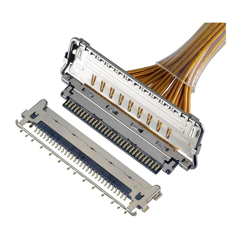
IPEX

IPEX CABLINE-CX II PLUG Without Cover User manual

IPEX CABLINE-VS II PLUG User manual

IPEX

IPEX CABLINE-VS II PLUG User manual
IPEX CABLINE-UX II PLUG User manual

IPEX

IPEX CABLINE-UX II PLUG User manual

IPEX CABLINE-UY User manual

IPEX

IPEX CABLINE-UY User manual

IPEX CABLINE-UY 20857-0 T-0 Series User manual
IPEX

IPEX CABLINE-UY 20857-0 T-0 Series User manual

IPEX CABLINE-CAL User manual

IPEX

IPEX CABLINE-CAL User manual

IPEX ISH20P User manual

IPEX

IPEX ISH20P User manual
IPEX CABLINE-VS IIF User manual

IPEX

IPEX CABLINE-VS IIF User manual

Popular Cables And Connectors manuals by other brands

S6 HVS-6204 user manual

S6

S6 HVS-6204 user manual

Leviton 6S10G-S6A instructions

Leviton

Leviton 6S10G-S6A instructions

Black Box AC156A-8 user manual

Black Box

Black Box AC156A-8 user manual

NCR 7403-K112 Kit instructions

NCR

NCR 7403-K112 Kit instructions

AMX MXA-UENET-PAN installation guide

AMX

AMX MXA-UENET-PAN installation guide

Philips SWV2027 Specifications

Philips

Philips SWV2027 Specifications

Kvaser U100-X1 user guide

Kvaser

Kvaser U100-X1 user guide

Extron electronics RG6-5 Specifications

Extron electronics

Extron electronics RG6-5 Specifications

BERNSTEIN SEU-1/0-T45 Series instruction manual

BERNSTEIN

BERNSTEIN SEU-1/0-T45 Series instruction manual

Marmitek SPLI' 422 user manual

Marmitek

Marmitek SPLI' 422 user manual

EarthPeople Technology EPT 232R-US-R1 user manual

EarthPeople Technology

EarthPeople Technology EPT 232R-US-R1 user manual

Renkforce DVD Maker II operating instructions

Renkforce

Renkforce DVD Maker II operating instructions

Lindy 38240 user manual

Lindy

Lindy 38240 user manual

MAYSER SP installation instructions

MAYSER

MAYSER SP installation instructions

Staubli CombiTac MA213-06 Assembly instructions

Staubli

Staubli CombiTac MA213-06 Assembly instructions

Philips SWA2110NB Specifications

Philips

Philips SWA2110NB Specifications

Philips SWV3534 Specifications

Philips

Philips SWV3534 Specifications

Altronix eBridge100RMT Kit installation guide

Altronix

Altronix eBridge100RMT Kit installation guide

manuals.online logo
manuals.online logoBrands
  • About & Mission
  • Contact us
  • Privacy Policy
  • Terms and Conditions

Copyright 2025 Manuals.Online. All Rights Reserved.