manuals.online logo
Brands
  1. Home
  2. •
  3. Brands
  4. •
  5. IPEX
  6. •
  7. Cables And Connectors
  8. •
  9. IPEX CABLINE-UM User manual

IPEX CABLINE-UM User manual

1/ 15
Document No.
HI
M
-
18033
-
04
EN
Confidential
C
I
-
PEX Inc.
QKE-DFFDE09-03 REV.8
CABLINE®-UM
Part No.Plug:20877-0**T-0※Receptacle:20879-0**E-0※
Instruction Manual
4 S20389 August 6, 2020 T.Masunaga -H.Ikari
3 S19758 December 13, 2019
T.Masunaga -H.Ikari
2 S19466 August 1, 2019 T.Masunaga -H.Ikari
1 S18713 August 1, 2019 Y.Miyazaki T.Masunaga H.Ikari
Rev. ECN Date Prepared by Checked by Approved by
CABLINE
-
UM
Instruction Manual
Document No.
HI
M
-
18033
-
04EN
2/ 15
Confidential
C
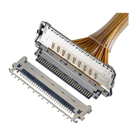
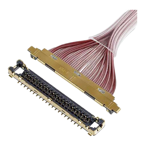
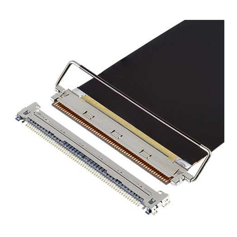
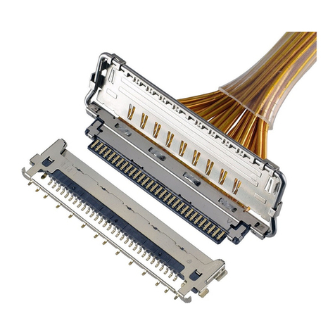
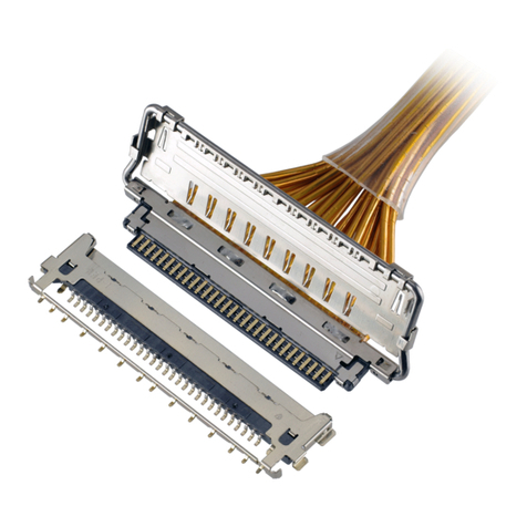
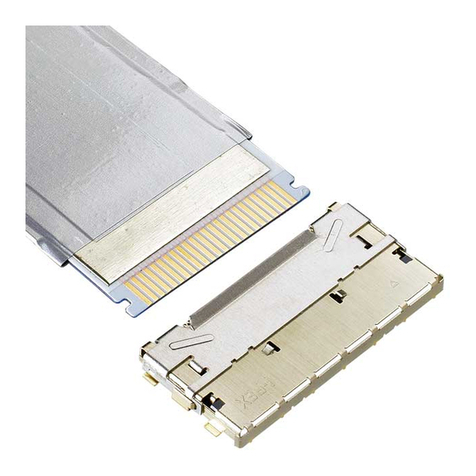
This manual is to explain the insertion & withdrawal methods and important points in handling of
CABLINE-UM connector plug with cable for the purpose of proper use.
【Connector Name, Part number】
◆The cable side connector
Product Name : CABLINE-UM Plug
Part No. : 20877-0**T-0※
◆The PCB side connector
Product Name : CABLINE-UM Receptacle
Part No. : 20879-0**E-0※
“ ** ” part shows the number of the connector position.
“ ※ ” part shows the variation. Please refer to the drawing for details.
CABLINE
-
UM
Instruction Manual
Document No.
HI
M
-
18033
-
04EN
3/ 15
Confidential
C
Lock cover finger hook
【Names of each part of the connector.】
Mating direction
I-PEX mark
Lock cover
Plug finger hook
Lock cover open
Plug
Receptacle
CABLINE
-
UM
Instruction Manual
Document No.
HI
M
-
18033
-
04EN
4/ 15
Confidential
C
【Comparing Plug parts numbers】
【Comparing Receptacle parts numbers】
20879-0**E-01
Shell Soldering Area
Refer to red dotted box below.
PULL TAPE HOLDER
PULL TAPE
20877-0**E-02
Without Lock Cover
20877-0**E-03
With PULL TAPE HOLDER
20877-0**E-01
With Lock Cover
20879-0**E-02
Shell Soldering Area
Refer to blue dotted box below.
CABLINE
-
UM
Instruction Manual
Document No.
HI
M
-
18033
-
04EN
5/ 15
Confidential
C
【Connector Insertion Manual】
1.Which direction to mate
As shown in Fig.1, make sure to place a cable on non-soldered tail side.
Fig.1 Fig.2 Correct Connector Mating View
CAUTION
Do not mate the connector while cable is at soldered tail side.
Fig.3
・As shown in Fig.4 and 5, Please set it so that both ends of PLUG are located within the "[ ]" of silk
print on PCB.
Fig.4 With Lock cover Fig.5 Without Lock cover
Soldered tail side
Cable
Inside silk print on
PCB
Silk print on PCB
The shape of plug
The shape of plug
Silk print on PCB
Inside silk print on
PCB
Non-soldered tail side
Soldered tail side
CABLINE
-
UM
Instruction Manual
Document No.
HI
M
-
18033
-
04EN
6/ 15
Confidential
C
2.How to Mate
Push the center of cable connector vertically until it clicks.
The clicking shows the mating completion. [Fig. 6]
Push both ends of the connector to make sure the mating is completed. [Fig. 7]
Fig.6 Fig.7
CAUTION
・A support shall be designed and placed under PCB in order to prevent PCB from being deformed
when cable connector is inserted with a pressing.
・The initial connector insertion angle allowance is given in Fig.8. Please set so that it becomes
parallel without applying excessive force afterwards. Do not force to press cable connector when
the insertion angle is out of this allowance angle.
Note 1. One side mating: Receptacle and plug mating slot side wall are touched on one end
Fig.8 Insertion angle allowance
Then push both connector ends and check the mating
condition to ensure that either end is securely inserted.
One side mating Note 1
Push the center of connector
12° MAX.
One side mating Note 1
12° MAX. 12° MAX.
CABLINE
-
UM
Instruction Manual
Document No.
HI
M
-
18033
-
04EN
7/ 15
Confidential
C
【How to Withdraw Cable Connector by finger】
①Lift a lock cover finger hook outward on one end and repeat it again on opposite side to release lock cover.
Make sure that the inner lock part is completely released. (see Fig.9)
② TYPE 1
Hook both ends of the Plug with the nail and withdraw the connector. (see Fig.10)
TYPE 2
Jump up both ends of the plug one by one and withdraw the connector. (see Fig.11)
Fig.9
Fig.10 TYPE 1
Fig.11 TYPE 2
LOCK
CABLINE
-
UM
Instruction Manual
Document No.
HI
M
-
18033
-
04EN
8/ 15
Confidential
C
【How to Withdraw Cable Connector by pull jig】
①Lift a lock cover finger hook outward on one end and repeat it again on opposite side to release lock cover.
Make sure that the inner lock part is completely released. (see Fig.12)
②Slide the “pull jig” from the side of a cable and attach to the cable connector.(see Fig.13)
③The jig shall be moved until it reach a stopper just as it hold the cable connector .(see Fig.14)
④Lift up the jig vertically to the PCB surface.(see Fig.15)
Fig.12
Fig.13
Fig.14
The front view
The side view
LOCK
The front view
The side view
The back view
Stopper
CABLINE
-
UM
Instruction Manual
Document No.
HI
M
-
18033
-
04EN
9/ 15
Confidential
C
Fig.15
【Pull Jig】
When withdrawal using pull jig, jig shape is presented in Fig.16 for reference.
pos. A B C D
30P 18.2
16.6
12.8
15.5
40P 22.2
20.6
16.8
19.5
Unit: mm
Fig.16 Reference : Plug Pull Jig
The front view
The side view
CABLINE
-
UM
Instruction Manual
Document No.
HI
M
-
18033
-
04EN
10 / 15
Confidential
C
CAUTION
・Do not lift lock cover finger hook inward or excessive force applied to the connectors may
damage them.
・Do not unmate a cable connector by pulling cable.
・When withdrawing the connector, we recommend that you pull the finger perpendicular to PCB.
When removing one side (cable pitch direction) first, please do not apply load to the top of
the connector. (see Fig.)
・Allowable mating angle is shown in Fig.15. When the jig is lifted up to un-mate the cable connector,
The unmating angle must be with in this tolerance.
Fig.19
Allowance
connector mating angle
Fig.17
2° MAX. 2° MAX.
Fig.18
Do not apply load
CABLINE
-
UM
Instruction Manual
Document No.
HI
M
-
18033
-
04EN
11 / 15
Confidential
C
CAUTION
・Do not unmate plug before opening lock cover, or it may damage receptacle and decreases plug
retention force.
Fig.20 Unmating connectors by force
Initial
Damaged
Photo
.1
Damaged
RECE.
CABLINE
-
UM
Instruction Manual
Document No.
HI
M
-
18033
-
04EN
12 / 15
Confidential
C
[How to unmate by using PULL TAPE】
※For connector with PULL TAPE HOLDER only
①Place the TAPE attached to the PULL TAPE HOLDER vertically against PCB.
②Hold center of the PULL TAPE with fingers and pull up vertically to unmate plug from receptacle.
Fig.21 Mated Connector with PULL TAPE
Fig.22 Unmating connectors by pulling PULL TAPE
CABLINE
-
UM
Instruction Manual
Document No.
HI
M
-
18033
-
04EN
13 / 15
Confidential
C
CAUTION
・Do not pull one side of the PULL TAPE and rotate it while unmating. [Fig. 23]
Do not pull the PULL TAPE toward arrowed direction, or it may tear the PULL TAPE
and deform SHELL-A and PULL TAPE HOLDER. Make sure to hold center of the PULL TAPE
and pull it up vertically. [Fig. 24]
・Do not exceed PULL TAPE slanted allowance angle while connectors were mated. [Fig. 25]
Fig.23 Do not pull one side of the PULL TAPE
Fig.24 Prohibited PULL TAPE pulling direction
Fig.25 PULL TAPE slanted allowance angle
2° MAX. 2° MAX.
CABLINE
-
UM
Instruction Manual
Document No.
HI
M
-
18033
-
04EN
14 / 15
Confidential
C
【Caution in Cable Connector Handling】
・Handle the cable connector carefully in cable harnessing work so that pulling force is NOT applied to specific
cables.
・Be careful so that pulling force and/or repeated bending force is NOT applied to the cable attachment part
of a cable connector.
・Do not pull cable that will apply excess force to it or it may damage or unmate the connectors. [Fig. 27]
・Do not pull cable to unmate connectors or it may damage receptacle. [Fig. 28]
Fig.27-1 Fig.27-2
Fig.28-1 Fig.28-2 Photo.2
It is recommended to fix a cable in order to prevent pulling
force from being applied to the cable attachment part.
Cable Attachment Part of a Connector
Fig.26
CABLINE
-
UM
Instruction Manual
Document No.
HI
M
-
18033
-
04EN
15 / 15
Confidential
C
【Recommend Vacuum Nozzle Design for Receptacle】
Figure 29 shows the recommended vacuum areas of receptacle top surface. If current vacuum nozzle for
mounter cannot vacuum well, refer to figure 30 for recommended vacuum nozzle design.
Fig.
30 Recommended Vacuum Nozzle Design
[
Unit:
mm]
Vacuum area Vacuum area
Vacuum area
Vacuum area
Fig.2
9
R
ecommended
Receptacle Vacuum Area
[
Unit:
mm]
・
20
87
9
-
040
E
-
01
・
20
87
9
-
030
E
-
01
・
20
87
9
-
040E
-
02
・
20
87
9
-
030E
-
02
Vacuum nozzle

Other IPEX Cables And Connectors manuals
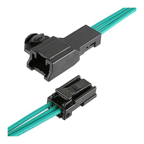
IPEX CABLINE-VS IIF User manual

IPEX

IPEX CABLINE-VS IIF User manual

IPEX CABLINE-CAF User manual

IPEX

IPEX CABLINE-CAF User manual
IPEX MINIFLEX 4-ST User manual

IPEX

IPEX MINIFLEX 4-ST User manual

IPEX EVAFLEX 5-SE-GHT User manual

IPEX

IPEX EVAFLEX 5-SE-GHT User manual

IPEX CABLINE-UM PLUG User manual

IPEX

IPEX CABLINE-UM PLUG User manual

IPEX CABLINE-CX II PLUG Without Cover User manual

IPEX

IPEX CABLINE-CX II PLUG Without Cover User manual

IPEX CABLINE-VS User manual

IPEX

IPEX CABLINE-VS User manual

IPEX MINIFLEX 2-BF User manual

IPEX

IPEX MINIFLEX 2-BF User manual

IPEX ISH User manual

IPEX

IPEX ISH User manual

IPEX EVAFLEX 5-HD User manual

IPEX

IPEX EVAFLEX 5-HD User manual

IPEX ISH User manual

IPEX

IPEX ISH User manual

IPEX MP-A 03 User manual

IPEX

IPEX MP-A 03 User manual

IPEX CABLINE-UY 20857-0 T-0 Series User manual

IPEX

IPEX CABLINE-UY 20857-0 T-0 Series User manual

IPEX CABLINE-UY User manual

IPEX

IPEX CABLINE-UY User manual

IPEX CABLINE-UA II PLUG User manual

IPEX

IPEX CABLINE-UA II PLUG User manual

IPEX CABLINE-CAL PLUG User manual

IPEX

IPEX CABLINE-CAL PLUG User manual

IPEX CABLINE-CA PLUG User manual

IPEX

IPEX CABLINE-CA PLUG User manual

IPEX AP-10 User manual

IPEX

IPEX AP-10 User manual

IPEX MINIFLEX 2-BF LK User manual

IPEX

IPEX MINIFLEX 2-BF LK User manual

IPEX FPL II User manual

IPEX

IPEX FPL II User manual
IPEX CABLINE-VS IIF User manual

IPEX

IPEX CABLINE-VS IIF User manual

IPEX ISH20P User manual

IPEX

IPEX ISH20P User manual

IPEX NOVASTACK 35-HDN User manual

IPEX

IPEX NOVASTACK 35-HDN User manual

IPEX 20613-0 E-0 Series User manual

IPEX

IPEX 20613-0 E-0 Series User manual

Popular Cables And Connectors manuals by other brands

Panduit DP6 PLUS installation instructions

Panduit

Panduit DP6 PLUS installation instructions

Siemens 3VF 3 operating instructions

Siemens

Siemens 3VF 3 operating instructions

Bosch CPP 0000 A installation manual

Bosch

Bosch CPP 0000 A installation manual

HRS DF51-6EP-2C manual

HRS

HRS DF51-6EP-2C manual

Staubli MC SLS425-SE/M Assembly instructions

Staubli

Staubli MC SLS425-SE/M Assembly instructions

Monacor HDMI-104 manual

Monacor

Monacor HDMI-104 manual

Philips SWV3133W Specifications

Philips

Philips SWV3133W Specifications

Philips SWV2141W Specifications

Philips

Philips SWV2141W Specifications

Insignia NS-SBNC100P92 Quick setup guide

Insignia

Insignia NS-SBNC100P92 Quick setup guide

TE Connectivity RD-316 instruction sheet

TE Connectivity

TE Connectivity RD-316 instruction sheet

Philips M1500A Cleaning, disinfection & sterilization guide

Philips

Philips M1500A Cleaning, disinfection & sterilization guide

Rockwell Automation Allen-Bradley 800G-ACGK1 installation instructions

Rockwell Automation

Rockwell Automation Allen-Bradley 800G-ACGK1 installation instructions

Philips SWA5510 Specifications

Philips

Philips SWA5510 Specifications

Philips SWA2112W Specification sheet

Philips

Philips SWA2112W Specification sheet

Labgear HD2-SP4 user guide

Labgear

Labgear HD2-SP4 user guide

Wattgate 350i Wiring instructions

Wattgate

Wattgate 350i Wiring instructions

Burndy Continental Industries thermOweld M-10310... instructions

Burndy

Burndy Continental Industries thermOweld M-10310... instructions

SCHÜTZE K3-450A22 operating instructions

SCHÜTZE

SCHÜTZE K3-450A22 operating instructions

manuals.online logo
manuals.online logoBrands
  • About & Mission
  • Contact us
  • Privacy Policy
  • Terms and Conditions

Copyright 2025 Manuals.Online. All Rights Reserved.