manuals.online logo
Brands
  1. Home
  2. •
  3. Brands
  4. •
  5. IPEX
  6. •
  7. Cables And Connectors
  8. •
  9. IPEX CABLINE-CA IIF User manual

IPEX CABLINE-CA IIF User manual

1/ 11
Document No.
HIM
-
1
7029
Confidential C
I
-
PEX Inc. QKE
-
DFFDE09
-
03 REV.8
CABLINE®-CA IIF
Part No.20856-040T-01
Instruction Manual
0 S17632 November 13, 2017
Y.Sasa T.Masunaga H.Ikari
Rev. ECN Date Prepared by Checked by Approved by
CABLINE
®
-
CA
IIF Instruction Manual
Document No.
HIM
-
1
7029
2/ 11
Confidential C
弊社、CABLINE-CA IIF CONN.の取り扱いに際して、本コネクタを安全に御使用頂くことを目的とし、コネクタの挿入・抜去の
手順及び注意点を記述致します。
This manual provides the mating & un-mating methods and cautions to handle CABLINE-CA IIF
connector properly.
【対象コネクタ名称・型番】 / Connector Name, Part number
◆プラグコネクタ (Plug connector)
名称 / Product Name : CABLINE-CA IIF SHELL ASS’Y
型番 / Part No. : 20856-040T-01
◆基板側コネクタ (Receptacle connector)
名称 / Product Name : CABLINE-CA II RECEPTACLE
型番 / Part No. : 20682-040E-0※
“※”はバリエーションになります。詳細は図面を参照願います。
(‘※’ part shows the variation. Please refer to a drawing for the details.)
【コネクタ各部名称】 Names of each part of the connector.
リセプタクルコネクタ
Receptacle 嵌合基準マーク
Datum pin mark
嵌合方向
Mating direction
LOCK BAR ASS’Y
図 1 (Fig 1.)
1: With Boss
2:Without Boss
I-PEX MARK
プラグコネクタ
PLUG
図 2 (Fig 2.)
Opened shell ass’y with FPC Closed shell ass’y with FPC
Spring
Spring
CABLINE
®
-
CA
IIF Instruction Manual
Document No.
HIM
-
1
7029
3/ 11
Confidential C
【コネクタ挿入手順/Connector Insertion Method】
①図 3 の様に、リセプタクルコネクタの基準ピンマークにプラグコネクタの基準ピンマークがくる様にセットする。
As shown in Fig.3, please set so that the datum pin mark of Plug connector and Receptacle connector
are matched.
②図 4 の様に、プラグコネクタの両側を水平に押し、隙間が無いかを確認する。
As shown in Fig.4, push both ends of Plug connector horizontally and confirm there is no gap.
プラグコネクタ基準ピン
Datum pin of Plug connector.
I-PEX mark
リセプタクルコネクタ基準ピン
Datum pin of Receptacle connector.
図 3 (Fig 3.)
図 4 (Fig 4.)
コネクタ両側を水平に押す
Push both end of connector horizontally
隙間が無いか確認
Confirm there is no gap
CABLINE
®
-
CA
IIF Instruction Manual
Document No.
HIM
-
1
7029
4/ 11
Confidential C
<注 1/Caution 1>
プラグコネクタの両側を水平に押して挿入してください。
片側ずつ押すと、図 5 の様に嵌合不完全になる恐れがあります。
In inserting, please push both ends of the plug connector horizontally.
When you push one end by one end, there is possibility to cause a gap as shown in Fig.3.
隙間が開いた状態で Cover を閉めると Cover とリセプタクルの Shell が干渉し、コネクタが変形する恐れがあります。
Do not close a cover if slant mating was confirmed. Interference of a cover and a receptacle shell
may deform the connector.
<注 2/Caution 2>
リセプタクルの Shell に設けてある挿入ガイドに沿って挿入してください。
ガイドに沿って挿入すれば、コネクタの変形は発生しません。
Please insert the connector along the insertion guide of the Receptacle connector.
As long as inserting along the guide, deformation of the connector doesn't occur.
SECT. X-X
Plug cover
Receptacle shell
隙間発生
Gap occurs NG
図 5 (Fig 5.)
図 6 (Fig 6.)
挿入ガイド/Insertion guide
図 7 (Fig 7.)
CABLINE
®
-
CA
IIF Instruction Manual
Document No.
HIM
-
1
7029
5/ 11
Confidential C
<注 3/Caution 3>
挿入時の水平方向のこじり角度は、5°以下でお願い致します。
5°以上での挿入は、コネクタ変形の原因となります。
Please keep insert slant 5 ° or less in horizontal direction.
By inserting with the slant more than 5°, deformation of the connector will occur.
<注 4/Caution 4>
Lock Bar ass’y を開き過ぎると Cover と FPC が干渉し FPC にダメージを与える
可能性がありますのでそれ以上押し込まないようにして下さい。
If cover is opened up more than its stopped position, cover edge may damage the FPC.
<注 5/Caution 5>
挿入開始時の垂直方向のこじり角度は、8°以下でお願いします。
8°以上での挿入は、コネクタ変形の原因となります。
At starting the insertion, please keep the slant 8 ° or less in vertical direction.
By inserting with the slant more than 8°, deformation of the connector will occur.
図 8 (Fig 8.)
5°
Damage
図 9 (Fig 9.)
図 10 (Fig 10.)
8°
CABLINE
®
-
CA
IIF Instruction Manual
Document No.
HIM
-
1
7029
6/ 11
Confidential C
<注 6/Caution 6>
Lock bar ass’y を操作しての挿入は行わないでください。Lock bar ass’y の変形及び
コネクタ破損の原因となります。
The lock bar and cover shall not be pushed or pulled for insertion to avoid deformation
or any connector damage.
<注 8/Caution 8>
プラグコネクタに基板方向の力を掛けながらの挿入は行わないでください。
基板に傷が入り、パターンの断線及びショートの原因となります。
Please do not apply force toward the PCB side to the plug connector in insertion.
PCB will be damaged like below and it may cause the disconnection of the pattern or the short.
傷発生/Scratch occurred
挿入/Insertion
Lock bar ass’y を引っ張っての挿入は NG
Do not push or pull Lock bar ass’y when mating the connector.
Push
Pull
Push, Pull
図 11 (Fig 11.)
図 12 (Fig 12.)
CABLINE
®
-
CA
IIF Instruction Manual
Document No.
HIM
-
1
7029
7/ 11
Confidential C
③Cover の図 13○部を基板側へ押し込み、リセプタクルコネクタの SHELL と Lock Bar をロックさせる。
Push two circled area of a cover down toward the PCB direction at a same time to lock receptacle
shell and lock bar.
Push
基板側へ押し込む
Push the lock cover/ bar downward
ロック状態
Locked condition
OK
NG
Receptacle shell が見える。
Receptacle shell is exposed.
Lock bar が下がっていないため、Receptacle shell が見えない。
Because the lock bar is not down, Receptacle shell is not exposed.
ロックが掛かっている事を確認
Check the lock is in locked position
図 13 (Fig 13.)
CABLINE
®
-
CA
IIF Instruction Manual
Document No.
HIM
-
1
7029
8/ 11
Confidential C
【コネクタ抜去手順/Connector Withdrawal Method】
①Lock bar の下図○部を反基板側へ引っ張ってリセプタクルコネクタとのロックを解除し、Lock bar ass’y を
回転させる。
Lift the circled positions of the pull bar upward to release the lock. Rotate the cover/bar as shown
on the bottom-right figure.
<注 9/Caution 9>
Lock bar ass’y の中央部を引き上げてのリセプタクルコネクタとのロック解除は行わないでください。
Lock bar ass’y の変形及びコネクタ破損の原因となります。
When releasing the lock, do not lift by the center of the lock bar ass’y.
There are possibility of lock bar ass’y and connector deformation.
引上げ/Lift
反基板側へ引っ張る
Lift the lock bar upward
中央部を引き上げてのロック解除は NG
Do not lift by the center of the Lock bar ass’y to release the lock
回転/Turn
図 14 (Fig 14.)
図 15 (Fig 15.)
CABLINE
®
-
CA
IIF Instruction Manual
Document No.
HIM
-
1
7029
9/ 11
Confidential C
②図 16 の様に、プラグコネクタの両側を水平に引っ張り、抜去を行う。
As shown in Fig.14, hold both ends of the Plug connector and withdrawal it parallel.
<注 10/Caution 10>
抜去時の水平方向のこじり角度は、5°以下でお願い致します。
5°以上での抜去は、コネクタ変形の原因となります。
Please keep withdrawal slant 5 ° or less in horizontal direction.
By withdrawing with the slant more than 5°, deformation of the connector will occur.
コネクタ両側を水平に引っ張る
Pull both ends of connector horizontally
図 16 (Fig 16.)
5°
図 17 (Fig 17.)
CABLINE
®
-
CA
IIF Instruction Manual
Document No.
HIM
-
1
7029
10 / 11
Confidential C
<注 11/Caution 11>
Lock bar ass’y を操作しての抜去は行わないでください。Lock bar ass’y の変形及びコネクタ破損の
原因となります。
Do not withdraw the connector by pulling or pushing the Lock bar ass’y.
There are possibilities to cause the Lock bar ass’y and connector deformation.
<注 12/Caution 12>
プラグコネクタに基板方向の力を掛けながらの抜去は行わないでください。
基板に傷が入り、パターンの断線及びショートの原因となります。
Please do not apply force toward the PCB side to the plug connector in withdrawal.
PCB will be damaged like below and it may cause the disconnection of the pattern or the short.
Pull
Push
Push, Pull
図 18 (Fig 18.)
Lock bar ass’y を引っ張っての抜去は NG
Do not withdraw the connector by pulling or pushing the Lock bar ass’y.
抜去/Withdrawal
図 19 (Fig 19.)
傷発生/Scratch
CABLINE
®
-
CA
IIF Instruction Manual
Document No.
HIM
-
1
7029
11 / 11
Confidential C
【コネクタ取り扱いにおける注意事項/Cautions in handling the connector】
①コネクタ嵌合状態にて、プラグコネクタの FPC 及び Lock bar ass’y を垂直方向に引っ張らないで
ください。 リセプタクルコネクタの変形の原因となります。
Please do not pull the FPC or the lock bar ass’y of the mated plug connector to the vertical direction.
It may cause the receptacle connector’s deformation.
② FPC 引き回しの際は、コネクタ及び FPC に過大な力が掛からない様、ご注意願います。
コネクタ破損及び FPC 断線の原因となります。
In handling the FPC, please pay attention not to apply excessive force to the connector or the FPC.
It may cause the connector or the FPC breakage.
③ 常にコネクタに力が掛かるようなケーブル引き回しは、ご遠慮願います。
嵌合不良及びコネクタ破損の原因となります。
Continuous stress to the connector should not remain after assembly.
It may cause the mating defect or the connector breakage.
シェル変形
SHELL deformation
図 20 (Fig 20.)

This manual suits for next models

1

Other IPEX Cables And Connectors manuals
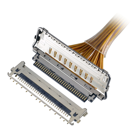
IPEX CABLINE-CA PLUG User manual

IPEX

IPEX CABLINE-CA PLUG User manual

IPEX CABLINE-VS IIF User manual

IPEX

IPEX CABLINE-VS IIF User manual

IPEX 20613-0 E-0 Series User manual

IPEX

IPEX 20613-0 E-0 Series User manual

IPEX ISH VW User manual

IPEX

IPEX ISH VW User manual

IPEX EVAFLEX 5-SE-GHT User manual

IPEX

IPEX EVAFLEX 5-SE-GHT User manual

IPEX NOVASTACK 35-HDN User manual

IPEX

IPEX NOVASTACK 35-HDN User manual

IPEX MINIFLEX 2-BF LK User manual

IPEX

IPEX MINIFLEX 2-BF LK User manual

IPEX MHF I User manual

IPEX

IPEX MHF I User manual

IPEX MINIFLEX 5-BF II User manual

IPEX

IPEX MINIFLEX 5-BF II User manual

IPEX CABLINE-UA II PLUG User manual

IPEX

IPEX CABLINE-UA II PLUG User manual

IPEX ISH Series User manual

IPEX

IPEX ISH Series User manual

IPEX CABLINE-CAF User manual

IPEX

IPEX CABLINE-CAF User manual

IPEX CABLINE-VSF User manual

IPEX

IPEX CABLINE-VSF User manual

IPEX EVAFLEX 5-HD User manual

IPEX

IPEX EVAFLEX 5-HD User manual

IPEX CABLINE-VS IIF User manual

IPEX

IPEX CABLINE-VS IIF User manual

IPEX AP-10 User manual

IPEX

IPEX AP-10 User manual

IPEX CABLINE-VS User manual

IPEX

IPEX CABLINE-VS User manual

IPEX ISH User manual

IPEX

IPEX ISH User manual

IPEX CABLINE-VS II PLUG User manual

IPEX

IPEX CABLINE-VS II PLUG User manual
IPEX CABLINE-VSF User manual

IPEX

IPEX CABLINE-VSF User manual

IPEX CABLINE-CAL User manual

IPEX

IPEX CABLINE-CAL User manual
IPEX CABLINE-UY 20857-0 T-0 Series User manual

IPEX

IPEX CABLINE-UY 20857-0 T-0 Series User manual

IPEX MHF 7S User manual

IPEX

IPEX MHF 7S User manual

IPEX CABLINE-CA II PLUS User manual

IPEX

IPEX CABLINE-CA II PLUS User manual

Popular Cables And Connectors manuals by other brands

Staubli CombiTac uniq CT-GOF Assembly instructions

Staubli

Staubli CombiTac uniq CT-GOF Assembly instructions

Altronix eBridge100RMT Kit installation guide

Altronix

Altronix eBridge100RMT Kit installation guide

PS Audio XStream instruction manual

PS Audio

PS Audio XStream instruction manual

Philips SWA2151W Specifications

Philips

Philips SWA2151W Specifications

Kramer 6010 user manual

Kramer

Kramer 6010 user manual

Lindy 38057 user manual

Lindy

Lindy 38057 user manual

Sensio Gamma SE988950 quick start guide

Sensio

Sensio Gamma SE988950 quick start guide

Speaka Professional 98 93 44 operating instructions

Speaka Professional

Speaka Professional 98 93 44 operating instructions

Philips SWV3434S specification

Philips

Philips SWV3434S specification

REMA DIN 80 technical information

REMA

REMA DIN 80 technical information

The Siemon Company LockIT Specifications

The Siemon Company

The Siemon Company LockIT Specifications

BK TECHNOLOGIES BKR0608 User instructions

BK TECHNOLOGIES

BK TECHNOLOGIES BKR0608 User instructions

Spector SPECTECH NATHAN T997 user manual

Spector

Spector SPECTECH NATHAN T997 user manual

Wayne-Dalton 3995 installation instructions

Wayne-Dalton

Wayne-Dalton 3995 installation instructions

Respironics 1001956 manual

Respironics

Respironics 1001956 manual

Cypress CLUX-14CEC Operation manual

Cypress

Cypress CLUX-14CEC Operation manual

IBM 9008-22L manual

IBM

IBM 9008-22L manual

Burndy Wiley ACC-F90-1 installation instructions

Burndy

Burndy Wiley ACC-F90-1 installation instructions

manuals.online logo
manuals.online logoBrands
  • About & Mission
  • Contact us
  • Privacy Policy
  • Terms and Conditions

Copyright 2025 Manuals.Online. All Rights Reserved.