manuals.online logo
Brands
  1. Home
  2. •
  3. Brands
  4. •
  5. IPEX
  6. •
  7. Cables And Connectors
  8. •
  9. IPEX CABLINE-VSF User manual

IPEX CABLINE-VSF User manual

1/ 12
Document No.
HI
M
-
1
3
0
10
Confidential
C
I
-
PEX Inc.
QKE-DFFDE09-03 REV.8
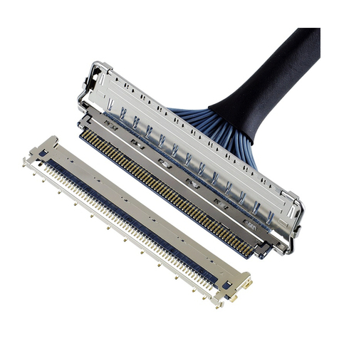
CABLINE®-VSF CONN.
Part No.PLUG: 20645-0**T-01,3049-0**1 RECEPTACLE: 20455-0**E-※※※
Instruction Manual
2S14534 December 22, 2014 H.A E.K
1S14257 June 30, 2014 H.I E.K
0S13474 December 10, 2013 H.Aoki J.Tateishi E.Kawabe
Rev. ECN Date Prepared by Checked by Approved by
CABLINE
-
VSF CONN.
Instruction
Manual
Document No.
HI
M
-
1
3
0
10
2/ 12
Confidential
C
弊社、CABLINE-VSF CONN.の取り扱いに際して、本コネクタを安全に御使用頂くことを目的とし、
コネクタの挿入・抜去の手順及び注意点を記述致します。
This manual provides the mating & un-mating methods and cautions to handle CABLINE-VSF connector properly.
【対象コネクタ名称・型番】 / Connector Name, Part number
◆FPC 側コネクタ (FPC side connector)
名称 / Product Name :CABLINE-VSF PLUG
型番 / Part No. :20645-0**T-01 ・・・・・・・ SHELL ASS’Y(With LOCK BAR)
3049-0**1 ・・・・・・・・・・ SHELL(Without LOCK BAR)
Fig 1. SHELL ASS'Y(With LOCK BAR) Fig 2. SHELL(Without LOCK BAR)
FPC assembly state FPC assembly state
◆基板側コネクタ (PCB side connector)
名称 / Product Name : CABLINE-VS RECEPTACLE
型番 / Part No. : 20455-0**E-※※※
“**”には各芯数番号が入ります。
( ‘**’ shows the number of the pin count).
“※”はバリエーションになります。詳細は図面を参照願います。
(‘※’ part shows the variation. Please refer to a drawing for the details.)
【コネクタ各部名称】 Names of each part of the connector.
FPC 側コネクタ
PLUG
嵌合基準
マーク
Datum pin mark
LOCK BAR
I
-
PEX MARK
基板側コネクタ
Receptacle
嵌合方向
Mating direction
CABLINE
-
VSF CONN.
Instruction
Manual
Document No.
HI
M
-
1
3
0
10
3/ 12
Confidential
C
【コネクタ挿入手順 / Connector Mating Method】
1.FPC 側コネクタのセット方法(Direction to mate.)
図3のように、基板側コネクタの基準 pin にFPC 側コネクタの基準 pin がくるように、セットします。
As shown in Fig.3, please set plug so that the datum pin mark of the plug connector and the receptacle connector are matched.
図3(Fig.3)
2.嵌合方法(How to mate.)
図4のように、FPC を水平に押し、ロック穴にロックが掛かると、嵌合完了となります。
As shown in Fig.4, push FPC horizontally until it is locked.
図4(Fig.4)
SHELL (LOCK BAR 無し)の場合 / For the connector SHELL(Without LOCK BAR).
FPC を水平に挿入する
Insert FPC to the connector horizontally.
⇒
FPC 側コネクタ基準 pin
Datum pin of plug connector.
Plug shell とRece shell がオーバーラップ
している事を確認
Check the overlap of Plug shell and Rece shell.
ロックが掛かっている事を確認
Check if it is locked.
基板側コネクタ基準 pin
Datum pin of receptacle connector.
I-PEX MARK
Rece shell
Plug
shell
ロックが掛かっている事を確認
Check if it is locked.
隙間がないか確認
Confirm whether there is space.
CABLINE
-
VSF CONN.
Instruction
Manual
Document No.
HI
M
-
1
3
0
10
4/ 12
Confidential
C
注意事項 / Cautions.
片側ずつ押すと、隙間が発生する恐れが有ります。(図 5)
When you push one end it might cause half mating. (Fig.5)
図5(Fig.5)
隙間発生 NG 状態
There is gap. NG
片側挿入 1
Push the one side.
片側挿入 2
Push the one side.
CABLINE
-
VSF CONN.
Instruction
Manual
Document No.
HI
M
-
1
3
0
10
5/ 12
Confidential
C
図6のように仮挿し状態時に、LOCK BAR を基板側コネクタ側に回転させ、FPC を水平に押す。
そして、突き当て面に隙間がないか確認する。
From temporary inserting condition as shown in Fig.6, turn LOCK BAR to the PCB connector side and push FPC horizontally. Then, confirm
whether there is space between mating confirmation surfaces.
図6(Fig.6)
嵌合が完了後、LOCK BAR を基板側に押し込み、基板側コネクタの SHELL とロックさせる。
After mated, push LOCK BAR to the PCB side and lock it to SHELL of the PCB side connector.
図7(Fig.7)
確認内容 Contents of confirmation.:
図8(Fig.8)
SHELL ASS’Y(LOCK BAR 付)の場合 / For the connector SHELL ASS’Y(With LOCK BAR).
FPC を水平に挿入する
Insert FPC to the connector horizontally.
隙間がないか確認
Confirm whether there is space.
隙間がないか確認
Confirm whether there is space.
ロックが掛かっている事を確認
Check the lock is locked.
ロックが掛かっている事を確認
Check the lock is locked.
CABLINE
-
VSF CONN.
Instruction
Manual
Document No.
HI
M
-
1
3
0
10
6/ 12
Confidential
C
注意事項 / Cautions.
片側ずつ押すと、隙間が発生する恐れが有ります。(図 9)
When you push one end it might cause half mating. (Fig.9)
図9(Fig.9)
図10 のように挿入時に LOCK BAR を押しながら挿入すると、LOCK BAR が変形したり、回転軸がコネクタ
から抜ける恐れがありますので、行わないでください。
When mating, in case you mate the connector pushing LOCK BAR as shown in Fig.10, there are possibilities to cause LOCK BAR
deformation or the rotation axis dropping out from the connector. Please don’t push LOCK BAR.
図10(Fig.10)
隙間発生 NG 状態
There is gap. NG
片側挿入 1
Push the one side.
片側挿入 2
Push the one side.
LOCK BAR をコネクタの挿入に使用しないでください。
Please don’t use LOCK BAR for insertion of connector.
回転軸
Rotation axis.
CABLINE
-
VSF CONN.
Instruction
Manual
Document No.
HI
M
-
1
3
0
10
7/ 12
Confidential
C
SHELL ASS’Y(LOCK BAR 有り品)及び SHELL(LOCK BAR 無し品)共通 /
Common matter by SHELL ASS’Y(With LOCK BAR) and SHELL(Without LOCK BAR).
水平方向 Horizontal direction.
本コネクタを安全に使用して頂く為に下写真の様にこじり角を 5°以下で御願い致します。
仮差しの状態から片側のみを挿入した場合、下図の様にこじり MAX.値が 5°となります。
5°以下であればコネクタの変形は発生致しません。
To use this connector safely, please keep mating angle to be less than 5°degree as shown in the figure below.
When you push only one side at the temporary insert condition, maximum slanted degree have to be less
than 5°. Deformation of the connector doesn't occur if insertion angle is kept less than 5 degree..
5°こじり状態 / 5°slanted condition.
垂直方向 Vertical Direction.
コネクタ挿入開始時の許容角度は下図の通りです。
The acceptable angle for mating is below.
下図のように、RECE. SHELL に挿入ガイドが設定されています。
ガイドに沿って挿入を御願い致します。ガイドに沿って挿入頂ければコネクタの変形は発生致しません。
RECEPTACLE SHELL has an insertion guide as shown in the figure below. Please insert plug along
with guide, then no deformation will occur.
SHELL 裏面のガイド形状
The guide inside of SHELL.
挿入開始時の許容角度 8°
The acceptable angle to start connector insertion is 8°.
5
°
CABLINE
-
VSF CONN.
Instruction
Manual
Document No.
HI
M
-
1
3
0
10
8/ 12
Confidential
C
【コネクタ抜去手順 / Connector Un-mating Method. 】
・コネクタを抜去する。Un-mating the connector.
図11 のように基板側コネクタに対し、FPC 側コネクタの FPC を矢印方向に平行に抜去する。
斜めに抜去すると、FPC の変形又は FPC のパターンにダメージを与える恐れがあります。
As shown in Fig.11, please pull out plug connector horizontally to PCB, slanted un-mating might
cause deformations of FPC or damage on FPC pattern.
平行抜去 OK 状態 / horizontal un-mating , OK condition
図11(Fig.11)
こじり抜去 NG 状態 / Slanted un-mating, NG
5°以下であればコネクタの変形は発生致しません。
To use this connector safely, please withdraw plug up to at 5° degree slanted angle as shown in the figure below.
so that it will not have deformation.
5°こじり状態 / 5°slanted un-mating status
SHELL (LOCK BAR 無し)の場合 / For the connector SHELL(Without LOCK BAR).
FPC を水平に引っ張る
Withdraw
FPC from connector horizontally
5
°
CABLINE
-
VSF CONN.
Instruction
Manual
Document No.
HI
M
-
1
3
0
10
9/ 12
Confidential
C
抜去手順Ⅰ/Un-mating method Ⅰ
図12 の①の箇所のどちらか一方を②の方向に LOCK BAR を上げ、基板側コネクタとのロックを解除後、
③の方向に LOCK BAR を回転させる。抜去は図 11 と同様の方法にて行う。
注意: ①以外で LOCK-BAR を②方向に上げようとすると、LOCK BAR が変形したり、コネクタが
破損する恐れがあります。
また、LOCK BAR の絶縁コート部を抜去に使用すると、LOCK BAR が変形する可能性が
ありますので、抜去には使用しないでください。
なお、絶縁コート部に金属や硬いものを当てると、コートが剥がれてしまう恐れがありますので、
当てないようにご注意願います。
Raise one of ①points of LOCK BAR in Fig.12 to the ②direction to release the lock with the PCB side connector, then, turn LOCK BAR
to ③direction. Un-mating method is same as described in Fig.11.
Caution: Except for ①part, if you pull up the LOCK-BAR towards direction ②, LOCK BAR would have
deformation or the connector would have damage. Also, if you use Insulated part of LOCK BAR
for Un-mating, LOCK BAR may deform. Please do not use it for Un-mating. Moreover,
if you hit the metal or hard material onto the insulating part, the coating have possibility to peel off
so that please understand to handle it carefully.
図12(Fig.12)
SHELL ASS’Y(LOCK BAR 付)の場合 / For the connector SHELL ASS’Y(With LOCK BAR).
③
①
①
②
絶縁
コート
部
/ Insulated part.
CABLINE
-
VSF CONN.
Instruction
Manual
Document No.
HI
M
-
1
3
0
10
10 / 12
Confidential
C
抜去手順 Ⅱ/ Un-mating method Ⅱ
図12 の①の箇所のどちらか一方を、②の方向に LOCK BAR を上げ、基板側コネクタとのロックを解除後、
図13 のように垂直になるように LOCK BAR を回転させ、図 14 のように③の垂直になっている箇所を
矢印方向に基板と水平方向になるように抜去してください。
注意: ①以外で LOCK-BAR を②方向に上げようとすると、LOCK BAR が変形したり、コネクタが
破損する恐れがあります。
また、LOCK BAR の絶縁コート部を抜去に使用すると、LOCK BAR が変形する可能性が
ありますので、抜去には使用しないでください。
なお、絶縁コート部に金属や硬いものを当てると、コートが剥がれてしまう恐れがありますので、
当てないようにご注意願います。
As Fig 12, ①, pull the one of ①points of LOCK BAR up towards ②direction to release the lock
from the PCB side connector and turn LOCK BAR up to horizontal as Fig 13. As Fig 14,
please make un-mating by pulling the horizontal part ③in parallel to PCB.
Caution: Except for ①part, if you pull up the LOCK BAR towards direction ②, LOCK BAR would have
deformation or the connector would have damage. Also, if you use Insulated part of LOCK BAR
for Un-mating, LOCK BAR may deform. Please do not use it for Un-mating. Moreover,
if you hit the metal or hard material onto the insulating part, the coating have possibility to peel off
so that please understand to handle it carefully.
図13(Fig.13)
図14(Fig.14)
②
③
③
CABLINE
-
VSF CONN.
Instruction
Manual
Document No.
HI
M
-
1
3
0
10
11 / 12
Confidential
C
【コネクタ取扱の注意】(CAUTION IN CABLE CONNECTOR HANDLING.)
FPC を垂直方向及び上煽り方向に引っ張ると、下写真の様に基板側コネクタのシェルが変形したり、FPC が
SHELL から抜ける恐れがありますので行わないで下さい。
また、LOCK BAR に関しても同様に、垂直方向に引っ張らないようにお願いいたします。
In case the FPC is pulled to the vertical direction or slanted direction, SHELL of the receptacle connector can deform or FPC might pull out
from plug. Please don’t pull FPC vertically or with slanted angle, LOCK BAR should not be pulled to the vertical direction.
垂直荷重 / Vertical load
シェル変形 / Shell deformation. FPC 抜け / FPC pull out from SHELL
LOCK BAR 垂直荷重 / LOCK BAR vertical load
Shell bend up
CABLINE
-
VSF CONN.
Instruction
Manual
Document No.
HI
M
-
1
3
0
10
12 / 12
Confidential
C
SHELL ASS’Y(LOCK BAR 有り品)及び SHELL(LOCK BAR 無し品)共通 /
Common matter by SHELL ASS’Y(With LOCK BAR) and SHELL(Without LOCK BAR).
・FPC コネクタの取り回しの際には特定の FPC に引っ張り力が集中しないように配慮ください。
・コネクタの FPC 取り付け部に引っ張り力及び繰り返し変位が加わらないように配慮ください。
・During setting FPC cable, please refrain from apply too much pulling force to FPC.
・Please refrain from applying pulling force or repeated bending force to the FPC assembly part of a plug connector.
図15 (Fig.15)
・図16 のように、矢印方向に常に力が加わるような FPC の引き回しを行うと、嵌合外れやコネクタの破損等
の恐れがありますので、ご注意願います。
・Please refrain from applying cable retention force as shown in the below picture which might case incomplete mating or breakage of connector.
図16(Fig.16)
FPC を固定し、コネクタの FPC 取り付け部に外力が加
わらないように配慮ください。
Fix the FPC so that the external force is NOT
applied to the FPC assembly part of connector.
コネクタの FPC 取り付け部
FPC assembly part of Connector.

Other manuals for CABLINE-VSF

1

This manual suits for next models

22

Other IPEX Cables And Connectors manuals
IPEX CABLINE-CAF User manual

IPEX

IPEX CABLINE-CAF User manual

IPEX MINIFLEX 2-BF User manual

IPEX

IPEX MINIFLEX 2-BF User manual
IPEX MHF I User manual

IPEX

IPEX MHF I User manual

IPEX CABLINE-VS II PLUG User manual

IPEX

IPEX CABLINE-VS II PLUG User manual

IPEX ISH VW User manual

IPEX

IPEX ISH VW User manual

IPEX CABLINE-VS User manual

IPEX

IPEX CABLINE-VS User manual

IPEX MHF-A User manual

IPEX

IPEX MHF-A User manual

IPEX CABLINE-CAF User manual

IPEX

IPEX CABLINE-CAF User manual

IPEX MINIFLEX 2-BF LK User manual

IPEX

IPEX MINIFLEX 2-BF LK User manual

IPEX CABLINE-UA II PLUG User manual

IPEX

IPEX CABLINE-UA II PLUG User manual

IPEX MP-A 03 User manual

IPEX

IPEX MP-A 03 User manual

IPEX CABLINE-UM User manual

IPEX

IPEX CABLINE-UM User manual

IPEX CABLINE-CAL PLUG User manual

IPEX

IPEX CABLINE-CAL PLUG User manual

IPEX CABLINE-CX II PLUG Without Cover User manual

IPEX

IPEX CABLINE-CX II PLUG Without Cover User manual

IPEX MINIFLEX 5-BF II User manual

IPEX

IPEX MINIFLEX 5-BF II User manual

IPEX NOVASTACK 35-HDP User manual

IPEX

IPEX NOVASTACK 35-HDP User manual

IPEX EVAFLEX 5-HD User manual

IPEX

IPEX EVAFLEX 5-HD User manual

IPEX MHF 7S User manual

IPEX

IPEX MHF 7S User manual

IPEX MHF-TI User manual

IPEX

IPEX MHF-TI User manual

IPEX ISH Series User manual

IPEX

IPEX ISH Series User manual

IPEX CABLINE-CX II With Cover User manual

IPEX

IPEX CABLINE-CX II With Cover User manual

IPEX CABLINE-CA PLUG User manual

IPEX

IPEX CABLINE-CA PLUG User manual
IPEX MINIFLEX 4-ST User manual

IPEX

IPEX MINIFLEX 4-ST User manual
IPEX NOVASTACK-B User manual

IPEX

IPEX NOVASTACK-B User manual

Popular Cables And Connectors manuals by other brands

Philips SWV2166W Specifications

Philips

Philips SWV2166W Specifications

LEGRAND SPX 00 quick start guide

LEGRAND

LEGRAND SPX 00 quick start guide

Pioneer RD-HWK100 installation manual

Pioneer

Pioneer RD-HWK100 installation manual

Philips SWV2135W Specifications

Philips

Philips SWV2135W Specifications

Philips SWV3303W Specifications

Philips

Philips SWV3303W Specifications

Avenview SPLIT-HDSDI-4-RS user guide

Avenview

Avenview SPLIT-HDSDI-4-RS user guide

TRENDnet TEW-L202 - QUICK datasheet

TRENDnet

TRENDnet TEW-L202 - QUICK datasheet

Alpine KWE-901G7MIC user guide

Alpine

Alpine KWE-901G7MIC user guide

Philips SWV7114W Specifications

Philips

Philips SWV7114W Specifications

Keysight U4206A Quick Start and Accessory Guide

Keysight

Keysight U4206A Quick Start and Accessory Guide

Sunrich Tech USB to Parallel Cable user manual

Sunrich Tech

Sunrich Tech USB to Parallel Cable user manual

Schaltbau M1 Series manual

Schaltbau

Schaltbau M1 Series manual

Streetwize SWBC18 manual

Streetwize

Streetwize SWBC18 manual

EUFAB 16494 operating instructions

EUFAB

EUFAB 16494 operating instructions

JTS UA-948 instruction manual

JTS

JTS UA-948 instruction manual

OUNEVA VC05-0387 installation guide

OUNEVA

OUNEVA VC05-0387 installation guide

Deutsch DT Series Technical manual

Deutsch

Deutsch DT Series Technical manual

Staubli KBT16BV-NS/M Series Assembly instructions

Staubli

Staubli KBT16BV-NS/M Series Assembly instructions

manuals.online logo
manuals.online logoBrands
  • About & Mission
  • Contact us
  • Privacy Policy
  • Terms and Conditions

Copyright 2025 Manuals.Online. All Rights Reserved.