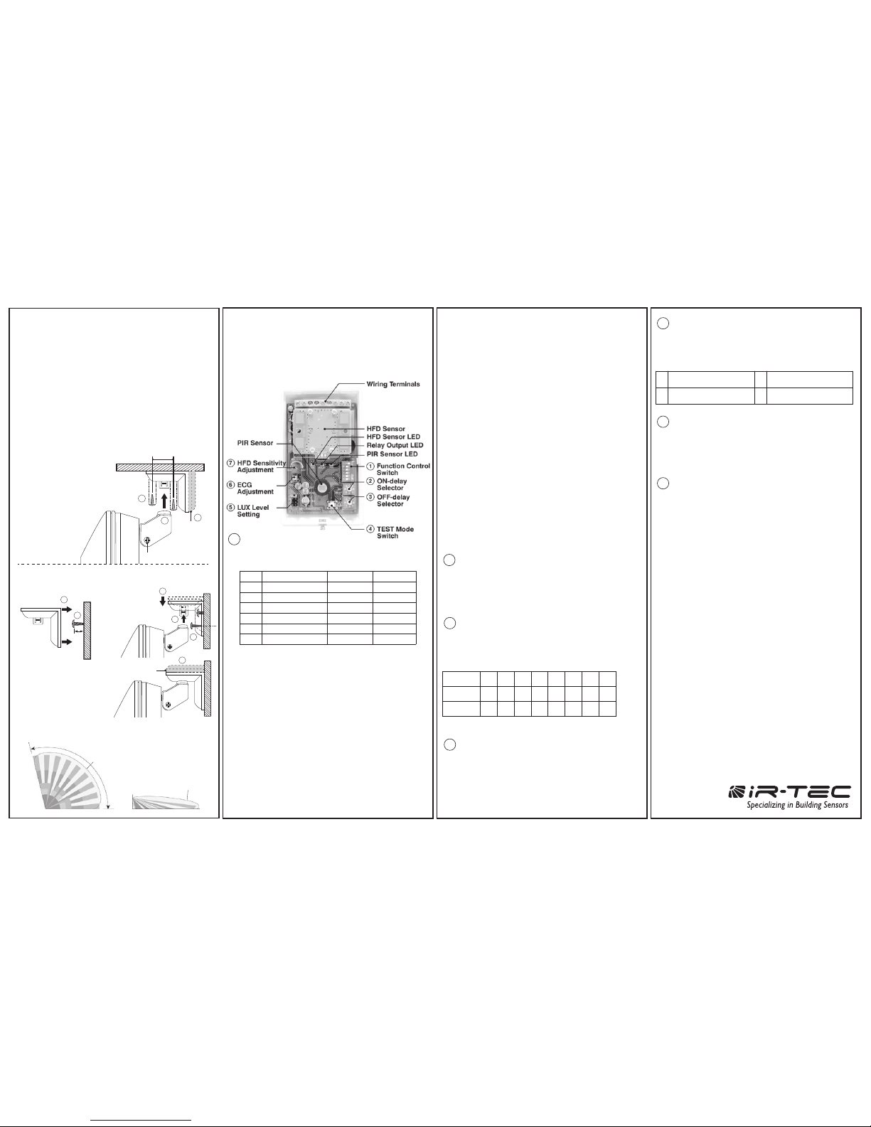
manuals.online logo
Brands
  1. Home
  2. •
  3. Brands
  4. •
  5. IR-Tec
  6. •
  7. Accessories
  8. •
  9. IR-Tec OS-551DT User manual

IR-Tec OS-551DT User manual

Hot Black
White
Red
Red
Black
Brown
Green
White
Red
Black
Blue
Red
Neut
Relay
Relay
DC24V
GND
COM
AC/DC
NO
NC
MS
DIM
Control
Hot
120~277V
Neutral
OS-551DT
PPU-301
Load
Hot
Neut
Yellow
Orange
Violet
Grey
OVERVIEW
The OS-551DT comes with pigtail wires for
connection to the corresponding wires of IR-TEC
power pack or BMS control. Each IR-TEC
PPU-300/301 power pack can supply power for up to
6 OS-551DT sensors. When more sensors are
connected, multiple power packs may be required.
Low Voltage Dual-Tech Occupancy Sensor
OS-551DT
INSTALLATION INSTRUCTIONS
APPLICATION NOTES
PIR sensor is more sensitive to the movements
“crossing” the detection zones than “toward” or
“away” the sensor unit. Avoid placing the sensor in
line with the path of occupant, if possible. In general,
mounting the sensor at corner area gives better
detection.
PIR sensor cannot “see” the movements behind
obstacles, such as furniture, shelf, glass or partitions.
As a general rule, ensure to place the sensor at where
the occupant could have clear view of the sensor.
HFD sensor may penetrate through certain types of
non-metallic partition material (glass, plaster,
plywood…etc) and detects the traffics outside of
desired range. Ensure to adjust the HFD sensitivity to
achieve optimal detection range.
Place the sensor at least at 5 ft. (1.5m) away from air
supply duct and fluorescent lighting to avoid false
activating.
For open office areas with partition which could block
the sensor view to occupant movements, it is
recommended to place the sensors over the
intersection of multiple workstations. For large areas of
open office or space, place multiple sensors so that
there is overlap coverage with each adjacent sensor.
1.
2.
3.
4.
5.
WIRING DIAGRAM
A. Auto-ON/Auto-OFF with PPU-301
B. Manual-ON/Auto-OFF and Auto-DIM
with PPU-300
Hot Black
White
Red
Red
Black
Brown
Green
White
Red
Black
Blue
Red
Neut
Relay
Relay
DC24V
COM
AC/DC
NO
NC
MS
DIM
Control
Manual
Hold ON
Hold OFF
Hot
120~277V
Neutral
OS-551DT
DIM
Dimmable light
1-10V
Hot
Neut
Yellow
Orange
Violet
Violet
Grey
Grey
Momentary Button
PPU-300
DC24V
GND
Control
Manual
Hold ON
Hold OFF
Orange
Grey
Brown
The OS-551DT is a low voltage dual technology
occupancy sensor designed to signal the occupancy
status for area lighting, or HVAC control, for energy
efficient building management. The sensor combines a
cutting edge Passive Infrared (PIR) sensor, a
state-of-the-art High Frequency Doppler (HFD) sensor,
and advanced signal processing firmware into one unit
to perform superior occupancy sensing capability. The
OS-551DT is ideal for the areas where motion may not
be easily detectable by a single technology sensor.
The OS-551DT is operated by 24V low voltage power.
When PIR sensor detects the presence of occupant
within its coverage, the sensor will activate a form C
dry contact for a period of OFF-delay time as
programmed. The delay timer will be reset if any
motion is detected by either PIR or HFD sensor before
delay time elapsed. An ON-delay can be enabled to
prohibit short-cycle restart or unwanted load activation
if the sensor is used to control HVAC operation. Both
ON and OFF delays can be easily set via two rotary
DIP switches on board. A potentiometer allows the
HFD sensitivity adjustment. The sensor output can be
set to inhibit when ambient light level is higher than the
threshold programmed. The ECG analog output is
available for constant level lighting control.
This sensor offers numerous control options which can
be enabled, or disabled via a 6-pole DIP switch on
board. 3 LED’s are available to indicate the sensing
status which can be disabled if necessary. A built-in
buzzer can be enabled to provide audible Delay-End
Warning (DEW) at the end of OFF-delay. The
SmartDelay can be enabled to automatically adjust the
OFF-delay based on the duration of previous
occupancies. Walk-Through mode can be enabled to
turn the light off 3 minutes after the area is initially
occupied but with no motion detected in the next 30
seconds. The FORCE-OFF delay can also be applied if
HFD sensor may detect the out-of-range motions thus
result in unwanted OFF-delay extensions. The
sensitivity of PIR sensor can be reduced for harsh
environment.
SPECIFICATIONS
Power supply
Current drain
Output contact
Infrared sensor
HFD sensor
Detectable speed
Mounting height
Detection range
ON-delay setting
OFF-delay setting
ALS level setting
Manual override
FORCE-OFF delay
Walk-thru mode
Op. humidity
Op. temperature
Dimensions
22~26 VAC/DC
20 mA @ 24 VAC, standby mode
Form C, max. 5A resistive load
Dual element pyroelectric sensor
X-band DRO type, patch antenna
0.33 ~ 10 ft/sec. (0.1 ~ 3 m/sec.)
6 ~ 12 ft (1.8 ~ 3.6 m)
110°, 50 ft @ 77°F (25°C)
0(disabled)/5”/10”/20”/30”/1’/3‘/5’
10”/1’/3’/5’/10’/20’/30’/60’
4-level, 2~2,000 lux
Momentary contact
5 times of OFF-delay set, if enabled
3 min. if no motion within 30 sec.
Max. 95% RH
-14°F ~ 122°F (-10°C ~ 50°C)
4.4”x2.6”x1.8” (112 x 66 x 45 mm)
P/N: 058-55100-005 Printed in Taiwanwww.irtec.com
This product may be covered by one or more U.S. patents or patent applications.
Please visit www.irtec.com for more information.
Turn power OFF at circuit breaker before connecting
Power Pack or Sensor.
CAUTION
This device complies with Part 15 of the FCC Rules. Operation is subject to the following two conditions:
(1)This device may not cause harmful interference, (2)This device must accept any interference received,
Including interference that may cause undesired operation.
FCC NOTES:
FCC ID: NRIOS-551DT
Wire all Class 2 circuits using types CL3, CL3P, CL3R,
or equivalent conductors.
Coupez l'alimentation au disjoncteur avant
d'installer Power Pack ou capteurs.
PRUDENCE
Câble toute classes 2 circuits CL3, CL39, CL3R ou
conducteur équivalent
Install the sensor at least 1ft. away from any occupant.
INDOOR USE ONLY
Utilisation a L'interieur Uniquement
DETECTION PATTERNS
Top View
Side View
110°
7.2’
16’ 32’ 50’
HFD Range
HFD Range
The OS-551DT offers numerous function controls and
operation settings available on board. To set the sensor
operation, remove the front cover by loosening the
locking screw at the sensor bottom.
SENSOR SETTINGS
Function Control Switch
1
ON-delay Selector
2
The Function Control Switch is a 6-pole DIP switch for
controlling the sensor operations as below.
3 LED’s are available on sensor board to indicate the
status of sensor operation. The LEFT one indicates HFD
sensor detection, the RIGHT one indicates PIR sensor
detection, and the CENTER one indicates sensor output
active.
No. Control OFF ON
1 LED indication
2 Buzzer output
3 SmartDelay
4 Walk-Through
5 FORCE-OFF
6 PIR sensitivity
disabled
disabled
disabled
disabled
disabled
Normal
enabled
enabled
enabled
enabled
enabled
Low
1. LED indication
The buzzer on board can be enabled to provide audible
indication for Delay-End Warning (DEW) and TEST mode.
TESTING THE SENSOR
After the sensor is mounted and wiring completed, it is
necessary to conduct a walk test to verify sensor
operation normal and detection coverage optimum.
When power is first applied to the sensor, the RIGHT LED
will blink about 1 minute for PIR sensor to warm up. The
sensor will be ready for testing after warm up expires.
Walk around within the desired coverage and observe
the LED indicators. The CENTER one should remain ON
as long as the relay is activated. The RIGHT one will light
on when PIR sensor detects the movement, and the
LEFT one will light on when HFD sensor detects.
Adjust the PIR sensor angle or apply the masking label
supplied on the lens to block the unwanted detection.
Adjust the HFD sensitivity as above-instructed to achieve
optimal coverage.
2. Buzzer output
SmartDelay can be enabled to automatically adjust the
OFF-delay from 3 to 30 minutes according to the duration
of previous occupancies. The OFF-delay time will be
constantly calibrated based on the history data collected.
3. SmartDelay
With Walk-Through (WT) mode enabled, the sensor will
deactivate its relay 3 minutes after the area is initially
occupied, if no activity is detected after the first 30
seconds. If activity is detected within the first 30 seconds,
the selected OFF-delay applies.
NOTE: The WT mode will not operate if OFF-delay is set
shorter than 3 minutes. ON-delay will be inhibited if the
WT mode is enabled.
4. Walk-Through
As HFD sensor may detect traffics behind certain type of
partition and result in unwanted OFF-delay extension.
Thus, the FORCE-OFF function can be enabled to
disengage the relay at 5 times of OFF-delay set, if only
the HFD sensor detects the movements during
OFF-delay duration.
5. FORCE-OFF
Lower PIR sensitivity can be achieved by setting the DIP
switch to ON position to eliminate unwanted activation.
ON-delay is the time given for sensor to avoid unwanted
load activation caused by short occupancy or pass
through traffics. Factory set ON-delay is disabled at “0”.
OFF-delay Selector
3
OFF-delay is the duration that relay contacts remain
engaged after the last motion sensed. Factory set is 10
minutes at “4”.
LUX Level Setting
5
4 different LUX levels can be set by placing the jumper
head at respective position, to inhibit the relay output if
ambient light level is higher than the threshold set.
ECG Adjustment
6
The ECG output can be used to achieve constant level
lighting control. This miniature potentiometer can be
adjusted to regulate the output of connected ECG lighting
fixture to the desired level.
HFD Sensitivity Adjustment
7
HFD sensor could detect the out-of-view traffics behind
partition. Ensure to adjust the potentiometer
counterclockwise to reduce the sensitivity if any of the
following situations occurred;
TEST Mode Switch
4
Pressing this button will activate a 5-minute TEST mode
(buzzer will beep twice). During TEST mode, the
ON-delay will be inhibited and the OFF-delay will be
shortened to 10 seconds for test convenience. Sensor will
return to normal operation automatically after times up.
6. PIR sensitivity
Set 01234567
0 5” 10” 20” 30” 1’ 3’ 5’
10” 1’ 3’ 5’ 10’ 20’ 30’ 60’
ON Delay
OFF Delay
A10 lux (approx. 1 fc)
B
C
D
30 lux (approx. 3 fc)
50 lux (approx. 5 fc)
24H (ALS disabled)
Walk around outside of desired range and the LEFT
LED is ON.
If the sensor is installed in a small room, and the
LEFT LED remains ON all the time even with no any
movement outside of desired range.
1.
2.
The OS-551DT comes with the bracket assembled
which allows it to be mounted on wall or ceiling with
two screws. To achieve optimal coverage, sensor angle
can be adjusted horizontally or vertically by loosening
the tightening screw on the bracket. Ensure to tighten
the tightening screw to hold the sensor position.
Mount the bracket base to the mounting surface with
screws.
Drill a proper hole on the mounting surface to lead
the sensor wires through.
Refer to the wiring diagram and connect the sensor
wires to the power pack or BMS control.
MOUNTING THE SENSOR
Ceiling mount
Wall mount
0.3”
1
2
1.
2.
3.
23
1
0.9”
Tightening Screw
End-cap
It is best to leave
approximately 6
inches between the
sensor and the wall
so that the tightening
screw can be
accessed.
Mount the first screw with approximately
0.3” head-off the wall for ease of base mounting.
Note: An end-cap
can be snap-in to
cover the back of
bracket.
3
5
4
6
End-cap
1 2
3
Sensor Internal
This device complies with Part 15 of the FCC Rules. Operation is subject to the following two conditions:
(1)This device may not cause harmful interference, (2)This device must accept any interference received,
Including interference that may cause undesired operation.

Other IR-Tec Accessories manuals

IR-Tec OS-361DT User manual

IR-Tec

IR-Tec OS-361DT User manual

IR-Tec trans LMD-109 User manual

IR-Tec

IR-Tec trans LMD-109 User manual

IR-Tec WallSenzr LDD-700 Series User manual

IR-Tec

IR-Tec WallSenzr LDD-700 Series User manual

IR-Tec OS-NET ON-LRD-209S User manual

IR-Tec

IR-Tec OS-NET ON-LRD-209S User manual

IR-Tec OS-551 User manual

IR-Tec

IR-Tec OS-551 User manual

IR-Tec wallSenzr LDT-700 Series User manual

IR-Tec

IR-Tec wallSenzr LDT-700 Series User manual

IR-Tec TRANS LMD-509 Series User manual

IR-Tec

IR-Tec TRANS LMD-509 Series User manual

IR-Tec WallSenzr LBS-701 Series User manual

IR-Tec

IR-Tec WallSenzr LBS-701 Series User manual

Popular Accessories manuals by other brands

Pilot Communications BRFN-30EF Use and care guide

Pilot Communications

Pilot Communications BRFN-30EF Use and care guide

Baumer 10157539 manual

Baumer

Baumer 10157539 manual

Sandstrom S650UPP14 instruction manual

Sandstrom

Sandstrom S650UPP14 instruction manual

Etrel load guard user manual

Etrel

Etrel load guard user manual

elco iNELS RFDSC-71N quick start guide

elco

elco iNELS RFDSC-71N quick start guide

ETEKCITY EDT-1USA manual

ETEKCITY

ETEKCITY EDT-1USA manual

MAC3 PresSystem user manual

MAC3

MAC3 PresSystem user manual

Vetako Ermak-10 user manual

Vetako

Vetako Ermak-10 user manual

HELLA Aglaia APS-90-Lite Assembly instructions

HELLA Aglaia

HELLA Aglaia APS-90-Lite Assembly instructions

Becker Centronic VarioControl VC180-II Assembly and operating instructions

Becker

Becker Centronic VarioControl VC180-II Assembly and operating instructions

Ultra Products Screen Cleaning Gel ULT33047 Specification sheet

Ultra Products

Ultra Products Screen Cleaning Gel ULT33047 Specification sheet

PCB Piezotronics PCB LOAD & TORQUE 4106-02A Installation and operating manual

PCB Piezotronics

PCB Piezotronics PCB LOAD & TORQUE 4106-02A Installation and operating manual

Cornelius Remcor 2849949020 installation instructions

Cornelius

Cornelius Remcor 2849949020 installation instructions

NeuLog NUL-227 Guide

NeuLog

NeuLog NUL-227 Guide

Verano V880 RAPOLLO installation manual

Verano

Verano V880 RAPOLLO installation manual

Arlo Audio Doorbell quick start

Arlo

Arlo Audio Doorbell quick start

Laser PB-8000LED quick start guide

Laser

Laser PB-8000LED quick start guide

Sloan Optima EL-1500 Series Maintenance Guide

Sloan

Sloan Optima EL-1500 Series Maintenance Guide

manuals.online logo
manuals.online logoBrands
  • About & Mission
  • Contact us
  • Privacy Policy
  • Terms and Conditions

Copyright 2025 Manuals.Online. All Rights Reserved.