Iron Bow MedView-V A01 Series User manual

1
Copyright 2019 Iron Bow Technologies
Iron Bow MedView™
Installation and User Guide
MEDVIEW-V-xxxx-A01
Document Version 1.32

2
Copyright 2019 Iron Bow Technologies
Copyright © 2019 Iron Bow Technologies
All Rights Reserved.
Specifications subject to change without notice.
For general inquiries, contact:
Iron Bow Healthcare Solutions
2303 Dulles Station Boulevard, Suite 400
Herndon, VA 20171
Toll: 800.338.8866
Tel: 703.279.3000
www.ironbowhealthcare.com
Forsupport, contact:
Iron Bow ClientService Center
Toll: 833.476.6269 (833.IRONBOW)
Email:CSC@ironbow.com

Copyright 2018 Iron Bow Technologies
Contents
Table of Figures ..........................................................................................................................................4
Introduction ................................................................................................................................................. 5
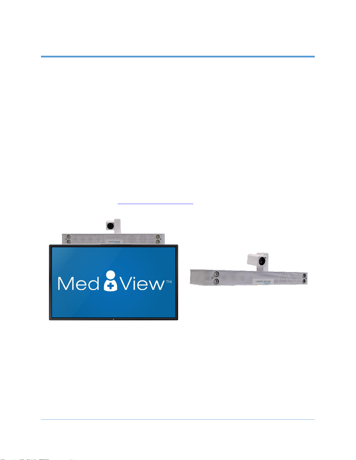
System Description.....................................................................................................................................5
System Installation .....................................................................................................................................7
Assembly on a monitor......................................................................................................................................... 8
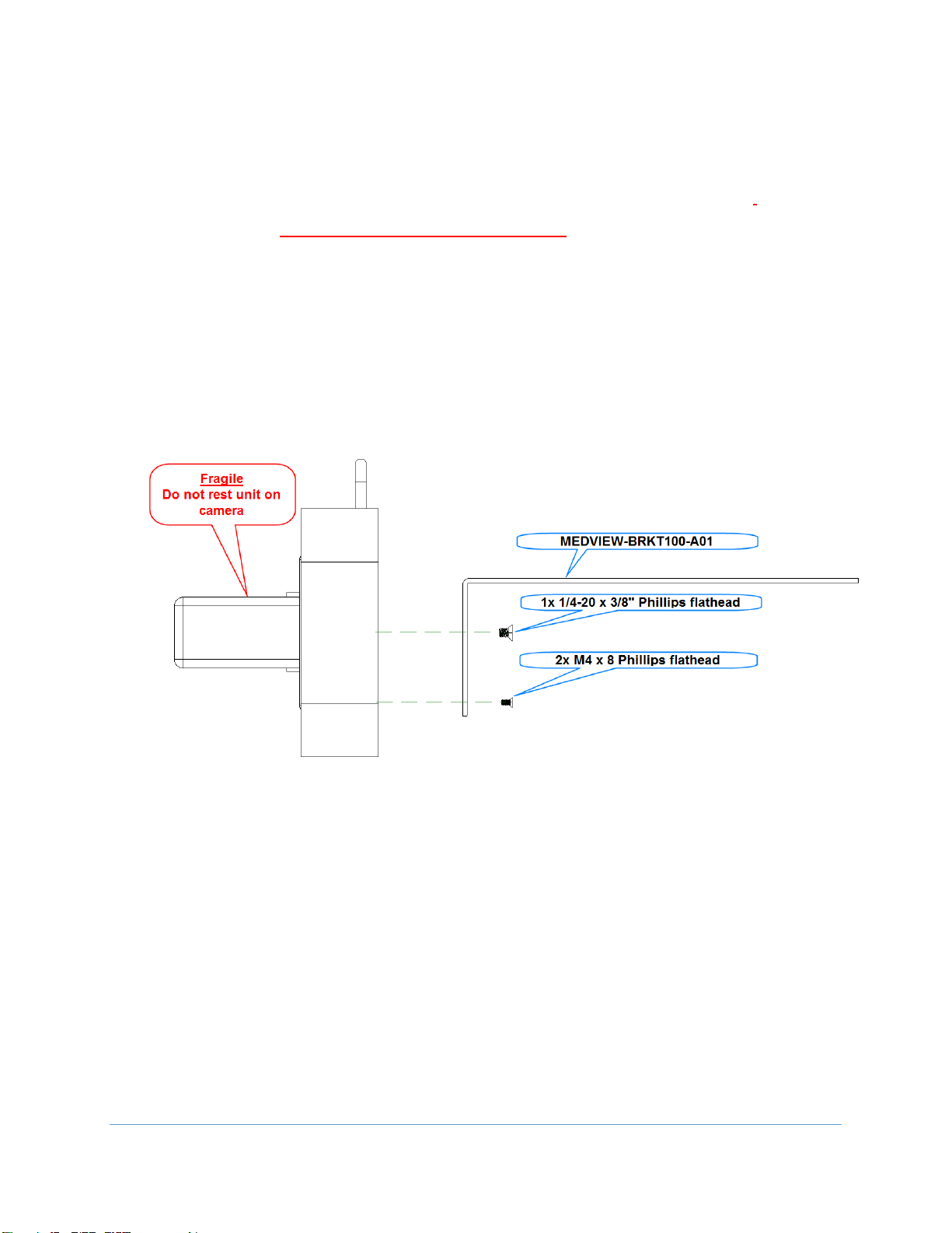
Attach the MedView to the MEDVIEW-BRKT100-A01 bracket ....................................................................... 8
Attach the MedView/MEDVIEW-BRKT100-A01 bracket assembly to the Monitor ........................................ 9
Assemble MEDVIEW-BRKT200-A01 to a Monitor ......................................................................................... 10
Assemble MEDVIEW-BRKT400-A01 to a Monitor ......................................................................................... 11
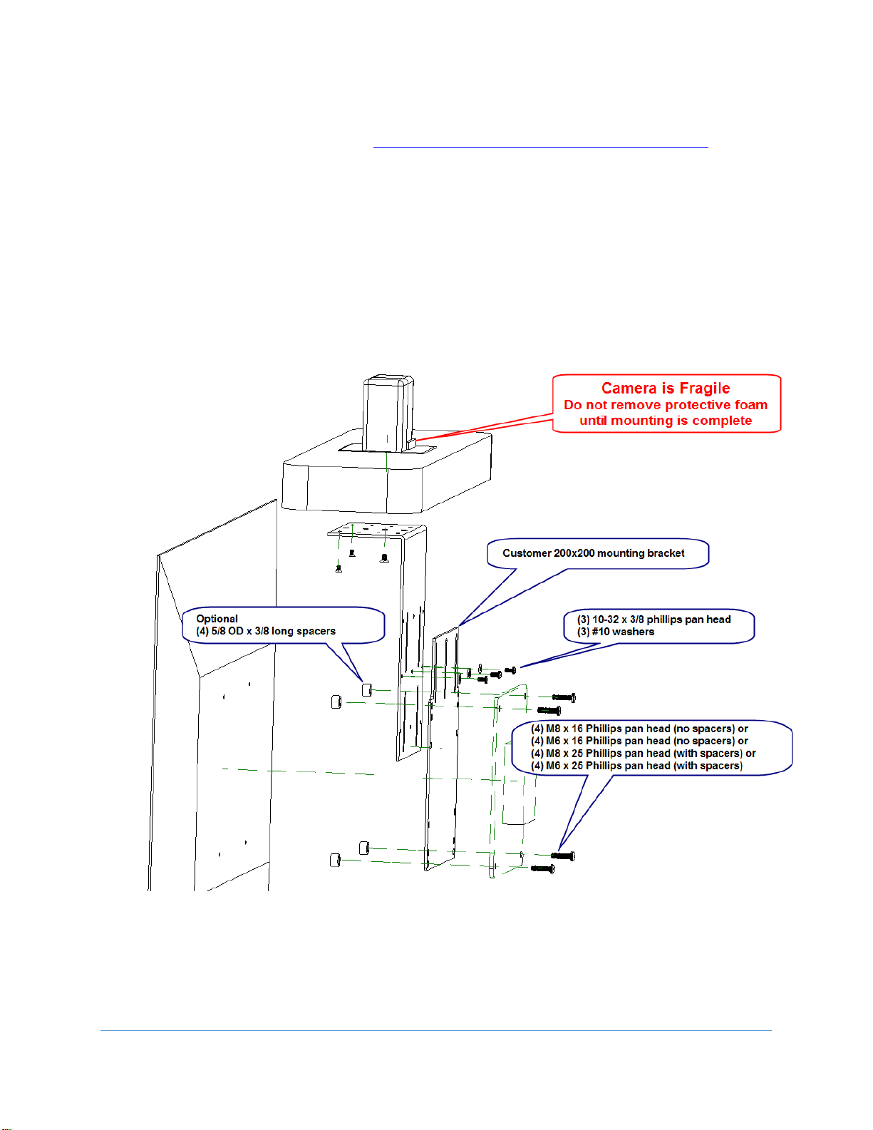
Assembly on a security camera mount (without an attached monitor) ....................................................... 12
Connections................................................................................................................................................... 12
Wi-Fi Network ............................................................................................................................................... 13
Connecting to the Monitor ................................................................................................................................. 14
Getting Started ..........................................................................................................................................15
Powering On and Off .......................................................................................................................................... 15
Powering On the MedView ........................................................................................................................... 15
Waking Up the MedView .............................................................................................................................. 15
Powering Off the MedView........................................................................................................................... 15
Restarting the MedView................................................................................................................................ 15
Connecting to the Network ................................................................................................................................ 15
Control Functions................................................................................................................................................ 16
MedView Administration ..........................................................................................................................17
Accessing the Vidyo Admin Settings ................................................................................................................... 17
Mandatory CLINiC Settings ................................................................................................................................. 17
Enable/Disable Auto Answer .............................................................................................................................. 18
Change Sleep Settings......................................................................................................................................... 18
Add Contacts....................................................................................................................................................... 19
Appendix #1: Specifications....................................................................................................................21
Specifications ...................................................................................................................................................... 22

4
Copyright 2019 Iron Bow Technologies
Table of Figures
Figure 1 - MedView with Integrated Sound Bar ...................................................................................................5
Figure 2 - MedView Major System Components..................................................................................................6
Figure 3 - Assemble MedView to Bracket.............................................................................................................8
Figure 4 - Assemble MedView to Monitor............................................................................................................9
Figure 5 - Add bracket for 200 x 200 Mount.......................................................................................................10
Figure 6 - Counterbore hole detail view .............................................................................................................11
Figure 7 - Add bracket for 400 x 400 mount.......................................................................................................11
Figure 8 - Assemble MedView on a post mount.................................................................................................12
Figure 9 - Connection Ports ................................................................................................................................12
Figure 10 - WiFi antenna assembly.....................................................................................................................13
Figure 11 - HDMI switch example.......................................................................................................................14
Figure 13 - MedView Dimensions .......................................................................................................................21

5
Copyright 2019 Iron Bow Technologies
Introduction
The MedView family of products from Iron Bow Healthcare Solutions consists of
purpose-built telehealth devices that integrate with existing in-room equipment to enable
the delivery of clinical healthcare from a distance.
This user guide covers the assembly and installation of the MedView. For Administration
and Configuration of the Iron Bow MedView, refer to VidyoRoom™ and
VidyoPanorama™ 600 Administrator Guide.
The MedView includes a hermetically sealed, high grade fanless computer running
VidyoRoom or VidyoConnect software, a high definition pan/tilt camera with a10x
optical/10x digital zoom, dual infrared illuminators for nighttime or darkened room
operation. The MedView camera, display and associated audio system enable high
quality video and audio calls between two parties or more.
The MedView incorporates a standard VESA mounting hole pattern for installation on
common wall mount brackets, or on table top stands and mobile carts.
You can find additional MedView resources, support information and other related
telehealth services at www.ironbowhealthcare.com.
Figure 1 - MedView with Integrated Sound Bar

6
Copyright 2019 Iron Bow Technologies
System Description
The primary components of the Iron Bow MedView are shown below:
1. System Camera
2. Infrared Illuminators
3. System Audio Bar
4. Serial Port (future)
5. Audio Out
6. Microphone Input
7. USB 3 Ports
8. Ethernet Network
9. DisplayPort Outputs
10. Power Connectors
11. WiFi antenna
Accessories included with MedView
Cat 5e cable, 6’
DisplayPort to HDMI cable, 3', blk
Power cord, NEMA 5/15P to C13, 6ft, blk
MedView user guide
Figure 2 - MedView Major System Components

7
Copyright 2019 Iron Bow Technologies
System Installation
The MedView is designed to be mounted on an existing wall arm that is already
supporting a monitor using the monitor VESA mounting hole pattern. Iron Bow sells
adapter plates to allow for mating the MedView with the VESA mount. Each mount uses
the smaller mounts as base components.
The customer is responsible for ensuring that the maximum weight (Medview plus
Monitor) can be supported by the existing wall mount.
Part Number
Description
MEDVIEW-BRKT100-A01
100 x 100 pattern
MEDVIEW-BRKT200-A01
100 x 200 or 200 x 200 pattern
MEDVIEW-BRKT400-A01
300 x 300 or 400 x 400 pattern
Some VESA combinations of monitor and Wall Mount are not recommended. See this table for required
brackets.
Monitor
Mount
Brackets
100x100
100x100
MEDVIEW-BRKT100-A01
VideoSecu ML20B bracket recommended1
100x100
200x200
n/a 2
100x200 or
200x200
100x100
n/a 2
100x200 or
200x200
200x200
MEDVIEW-BRKT200-A01
200x200
400x400
MEDVIEW-BRKT400-A01
400x400
200x200
MEDVIEW-BRKT400-A01
Additional M6 or M8 Nuts required
400x400
400x400
MEDVIEW-BRKT400-A01
1
Adapter allows the assembled MedView and brackets to slide onto a wall mount. Many wall mounts already
have this feature. Check your existing wall mount to see if this bracket is desirable.
2
Options are not possible without customization of the brackets or use of an adapter plate

8
Copyright 2019 Iron Bow Technologies
Assembly on a monitor
Attach the MedView to the MEDVIEW-BRKT100-A01 bracket
1. Position the MedView so it is facing down, with the hole pattern on the bottom exposed.
DO NOT REST THE UNIT ON THE CAMERA
a. Attach the MedView to the MEDVIEW-BRKT100-A01 bracket using the (2) M4x8 Phillips
flathead screws and/or the (1) ¼-20 x 3/8” flathead screw.
b. The unit can be adjusted forward and back to suit the situation, with 4 sets of holes available
for positioning. Use the (2) M4 flathead screws to lock the MedView parallel to the monitor
face.
c. If it is necessary to install the MedView so it it not parallel to the monitor face, the ¼-20
screw can be used alone and will allow the unit to be angled as needed.
Figure 3 - Assemble MedView to Bracket

9
Copyright 2019 Iron Bow Technologies
Attach the MedView/MEDVIEW-BRKT100-A01 bracket assembly to the Monitor
1. Place the monitor face down on a table being sure to protect the front face from scratches or
damage.
2. Position the (4) spacers over the VESA mount holes in the monitor. If the rear of the monitor is flat,
and nothing prevents the bracket from mounting flat to the surface, the spacers are not necessary.
3. Position the MedView and bracket on top of the spacers (on the monitor) so the VESA hole patterns
line up.
4. Position the Angled half of the ML20B bracket as shown, aligned with the VESA hole pattern.
5. Secure the bracket to the monitor using the screws provided.
a. Use the (4) M4x25 Phillips pan head screws to secure the bracket to the monitor.
b. If no spacers are used, use the (4) M4x18 Phillips pan head screws to secure the bracket to
the monitor.
Figure 4 - Assemble MedView to Monitor

10
Copyright 2019 Iron Bow Technologies
Assemble MEDVIEW-BRKT200-A01 to a Monitor
1. Follow the previous instructions for attaching the MedView to the MEDVIEW-BRKT100-A01 bracket.
2. Place the monitor face down on a table being sure to protect the front face from scratches or
damage.
3. Position the MedView/MEDVIEW-BRKT100-A01 assembly over the monitor. Locate the MEDVIEW-
BRKT200 bracket so the slots align with one of the set of (3) 10-32 threaded holes in the BRKT100
bracket while the bracket slots align with the monitor holes.
4. Secure the BRKT200 to the BRKT100 plate using the (3) 10-32 x 3/8 phillips pan head screws and (3)
#10 washers.
5. Secure the bracket assembly to the monitor using M6 or M8 pan head screws. With spacers, use
25mm long screws, and 16mm without spacers.
Figure 5 - Add bracket for 200 x 200 Mount

11
Copyright 2019 Iron Bow Technologies
Assemble MEDVIEW-BRKT400-A01 to a Monitor
1. Follow the previous instructions for attacheing the MedView to the MEDVIEW-BRKT100-A01 bracket.
2. Place the monitor face down on a table being sure to protect the front face from scratches or
damage.
3. Position the MedView/MEDVIEW-BRKT100-A01 assembly over the monitor.
4. Locate the MEDVIEW-BRKT200 bracket so the 200x200 hole
pattern is centered on the monitor. The counterbore
pockets must be facing away from the BRKT100 bracket.
5. Align the slots in the bracket with one of the set of (3) 10-32
threaded holes in the BRKT100 bracket.
6. Secure the BRKT200 to the BRKT100 plate using the (3) 10-32
x 5/16 phillips pan head screws and (3) #10 washers.
7. Attach the (2) MEDVIEW-BRKT400-A01 bracket arms to the
BRKT200 bracket using the (4) 10-32 x 5/16 flathead screws.
8. Secure the bracket assembly to the monitor using M6 or M8
pan head screws. With spacers, use 25mm long screws, and
16mm without spacers.
Figure 6 - Counterbore hole detail view
Figure 7 - Add bracket for 400 x 400 mount

12
Copyright 2019 Iron Bow Technologies
Assembly on a security camera mount (without an attached monitor)
While not common, the MedView
can be mounted to a ¼-20 threaded
video camera mount. A non-rotation
pin hole is included in the MedView
base plate.
Connections
The base MedView includes an AC power inlet, an Ethernet port for connecting to a wired
network, several USB 3 ports for connecting external devices including a
keyboard/mouse, which may be required for setting up the MedView system.
1. Power Cable (supplied)
2. Serial Port (future use)
3. Speaker Output –for adding external powered audio speaker(s). The external
speaker(s) will replace the built-in speaker system.
4. Microphone in –for adding an external microphone for local audio pickup. Will
disable two of the four internal microphones.
5. WiFi Antenna –WiFi is not recommended for fixed location installations, but can
be configured to work with the MedView if necessary.
6. Ethernet Port 1 –recommended connection to the local LAN/WAN (6’ cable
included in the kit)
7. Ethernet Port 2 –not currently used
8. DisplayPort 1 –install DisplayPort to HDMI cable (provided) to monitor or to a
signal priority device (ex. ACC-HDMISWITCH-A01)
9. DisplayPort 2 –not used
10. (4) USB 3.0 ports –use for special equipment
a. Keyboard/mouse for system setup
b. Spider Audio option (ACC-AUDIO-SPDR-A01)
Figure 9 - Connection Ports
Figure 8 - Assemble MedView on a post mount

13
Copyright 2019 Iron Bow Technologies
Wi-Fi Network
The MedView can be connected to either a wired (recommended) or wireless (Wi-Fi)
network. To operate from a Wi-Fi network, the two supplied antennas need to be attached
to the system.
Installing the Wi-Fi Antennas
1. Attach the two Wi-Fi antenna supplied with the unit to the MedView chassis
as shown. They should be easily threaded onto the exposed connector. Do
not overtighten.
Figure 10 - WiFi antenna assembly

14
Copyright 2019 Iron Bow Technologies
Connecting to the Monitor
If the monitor supports prioritization of inputs, then the DisplayPort/HDMI output from
the MedView can often be connected directly to the monitor HDMI input. Customer will
need to configure the monitor to respond as desired to the different inputs. See an Iron
Bow Applications engineer to review your specific conditions.
If the monitor does not provide input prioritization, then a governing switch will likely be
required. See the ACC-HDMISWITCH-A01 priority switch below for an example.
Non-HDMI monitor inputs
will likely require upscalers
or converters to transition
from one technology to
another. See the Iron Bow
Application engineer for
assistance.
Figure 11 - HDMI switch example

15
Copyright 2019 Iron Bow Technologies
Getting Started
Powering On and Off
Connect any required peripherals to the USB ports of the MedView before connecting the
MedView to AC power.
Powering On the MedView
To power on the MedView:
Connect the MedView to AC power. This will automatically power on the
integrated computer, camera and display of the MedView. A splash screen will
be displayed within several seconds.
Waking Up the MedView
The system goes to sleep after a set period with no activity. This value can be changed
from the Settings menu of the VidyoRoom administrator user interface (Admin UI)
To wake up the MedView:
The MedView will automatically wake up on receipt of an incoming call, or by
pressing any button on the infrared remote control.
Powering Off the MedView
Powering off the CLINiC is typically unnecessary. Most video endpoints remain
connected to the network and in stand-by mode until a call is placed or received.
However, you may need to power off the MedView if you need to move the MedView to
a different room.
To power off the MedView:
Disconnect the MedView from AC power.
Restarting the MedView
You can restart the MedView by powering off and powering on the MedView.
Connecting to the Network
Before you can make and receive video calls with the MedView, you must connect the
unit to the network. There are two ways you can connect to the network: using the
integrated Wi-Fi with external antenna, or using the 10/100/1G Ethernet port.
To connect the MedView to a Wi-Fi network, please refer to VidyoRoom™ and
VidyoPanorama™ 600 Administrator Guide,

16
Copyright 2019 Iron Bow Technologies
Control Functions
There are no control functions on the MedView device itself. An administrator will typically set up the
unit to auto answer at a pre-set volume. Users can purchase remote controls for the MedView that
allow for in-room call and volume control.
Iron Bow Part Number
Function
ACC-V-VOLCTRL-A01
Volume-control remote for Vidyo-based vCLINiC
and MedView products. USB connection with
approx. 10’ coiled tether.
ACC-V-REMOTE-A01
Functional remote control for Vidyo-based
vCLINiC and MedView applications. USB
connection with approx. 10’ coiled tether.
For more information on the MedView remote controls, refer to the Iron Bow Remote Control User
Guide available at https://ironbowhealthcare.com.

17
Copyright 2019 Iron Bow Technologies
MedView Administration
You can modify the default functions of the Vidyo based MedView by logging in as an
administrator to the VidyoRoom Admin UI and performing the desired changes.
For the complete set of instructions, please refer to the VidyoRoom and VidyoPanorama
600 Administrator Guide.
Accessing the Vidyo Admin Settings
To access the admin settings:
1. In your web browser address line, enter the system IP address. The Admin UI
Login tab appears.
NOTE: The system IP address is displayed on the screen when you first boot up
the Vidyo CLINiC. After boot-up, when not in a call, the IP address is displayed
in the bottom right hand corner of the screen.
2. In the Login tab, enter the admin login username (default is admin) and
password (default is password).
3. Click Login. The rest of Admin UI tabs appear.
4. Click the Settings tab to display all settings options.
Mandatory CLINiC Settings
The following settings are required for using the VidyoRoom SE software with the
CLINiC. These settings can be applied in the Preferences menu.
To apply the mandatory settings:
1. In the Admin UI, click the Settings tab.
2. If needed, click the blue triangle next to the word Preferences to view the
Preferences menu.
3. Make sure the options Enable AEC, Enable Audio Processing, Preview Local
Content and Enable HDMI-CEC are all unchecked. If any of these options are
checked, click in the corresponding box to uncheck them.
4. If you made any changes you want to save, click Save.

18
Copyright 2019 Iron Bow Technologies
Enable/Disable Auto Answer
You can change the way calls are answered from the CLINiC. The Vidyo CLINiC can be
set to answer incoming calls automatically or manually.
To enable automatic call answering:
1. In the Admin UI, click the Settings tab.
2. If needed, click the blue triangle next to the word Preferences to view the
Preferences menu.
3. Make sure the Auto Answer option is checked. If the option is unchecked, click
in the corresponding box to check the option.
4. Click Save.
To disable automatic call answering:
1. In the Admin UI, click the Settings tab.
2. If needed, click the blue triangle next to the word Preferences to view the
Preferences menu.
3. Make sure the Auto Answer option is unchecked. If the option is checked, click
in the corresponding box to uncheck the option.
4. Click Save.
Change Sleep Settings
The system goes to sleep after one hour with no activity.
To change when the system goes to sleep:
1. In the Admin UI, click the Settings tab.
2. If needed, click the blue triangle next to the word Preferences to view the
Preferences menu.
3. Change the Display Sleep Timeout value (default is 3600 seconds).
4. Click Save.
For changing any other settings, please refer to the VidyoRoom and VidyoPanorama 600
Administrator Guide.

19
Copyright 2019 Iron Bow Technologies
Add Contacts
Before you can place a call to an address using the CLINiC integrated control panel, you
must add the address to your list of contacts.
To add a new address to your list of contacts:
1. In the search box of the VidyoRoom pre-call menu, enter the desired address
As soon as you start typing, the addresses that match the typed characters and
that are reachable in your network will be populated under the search box.

20
Copyright 2019 Iron Bow Technologies
2. Once you finished typing the address or the system has displayed the desired
address under the search box, you can select the address. Use the mouse, arrow
keys on your keyboard or remote to move down from the search box and
highlight the contact. Press Enter on the keyboard or OK on the remote.
3. Use the mouse, arrow keys on your keyboard or remote to select Add to My
Contacts. Press Enter on the keyboard or OK on the remote to save the contact
to your list.
For more information on managing contacts, please refer to the VidyoRoom and
VidyoPanorama 600 Quick User Guide.
This manual suits for next models
3
Table of contents
Other Iron Bow Medical Equipment manuals
Popular Medical Equipment manuals by other brands

Dräger
Dräger Infinity Vista Instructions for use

Ossur
Ossur AFO Light Instructions for use

Olympic Medical
Olympic Medical OLYMPIC SMART SCALE 35 Operating and service instructions

Oxypharm
Oxypharm NOCOSPRAY 2 manual

Trumpf
Trumpf TruSystem 7000 instruction manual

AEIOMed
AEIOMed Everest 2 Quick Start Guide for Patients