Ironcraftusa.com Ironcraftusa.com1.1 Welcome2 3Table of Contents
WARNING
READ AND UNDERSTAND MANUAL.
To prevent personal injury or even death, be sure you read and understand all of the
instructions in this manual and other related OEM equipment manuals! The disc mulcher,
if not used and maintained properly, can be dangerous to users unfamiliar with its
operation. Do not allow operating, maintaining, adjusting, or cleaning of this disc mulcher
until the user has read this manual and has developed a thorough understanding of the
safety precautions and functions of the unit. This disc mulcher is designed for the specic
purpose of tree removal. DO NOT modify or use this disc mulcher for any application other
than that for which it was designed. Disc mulchers maintained or operated improperly or
by untrained personnel can be dangerous; exposing the user and/or bystanders to possible
serious injury or death.
INTRODUCTION
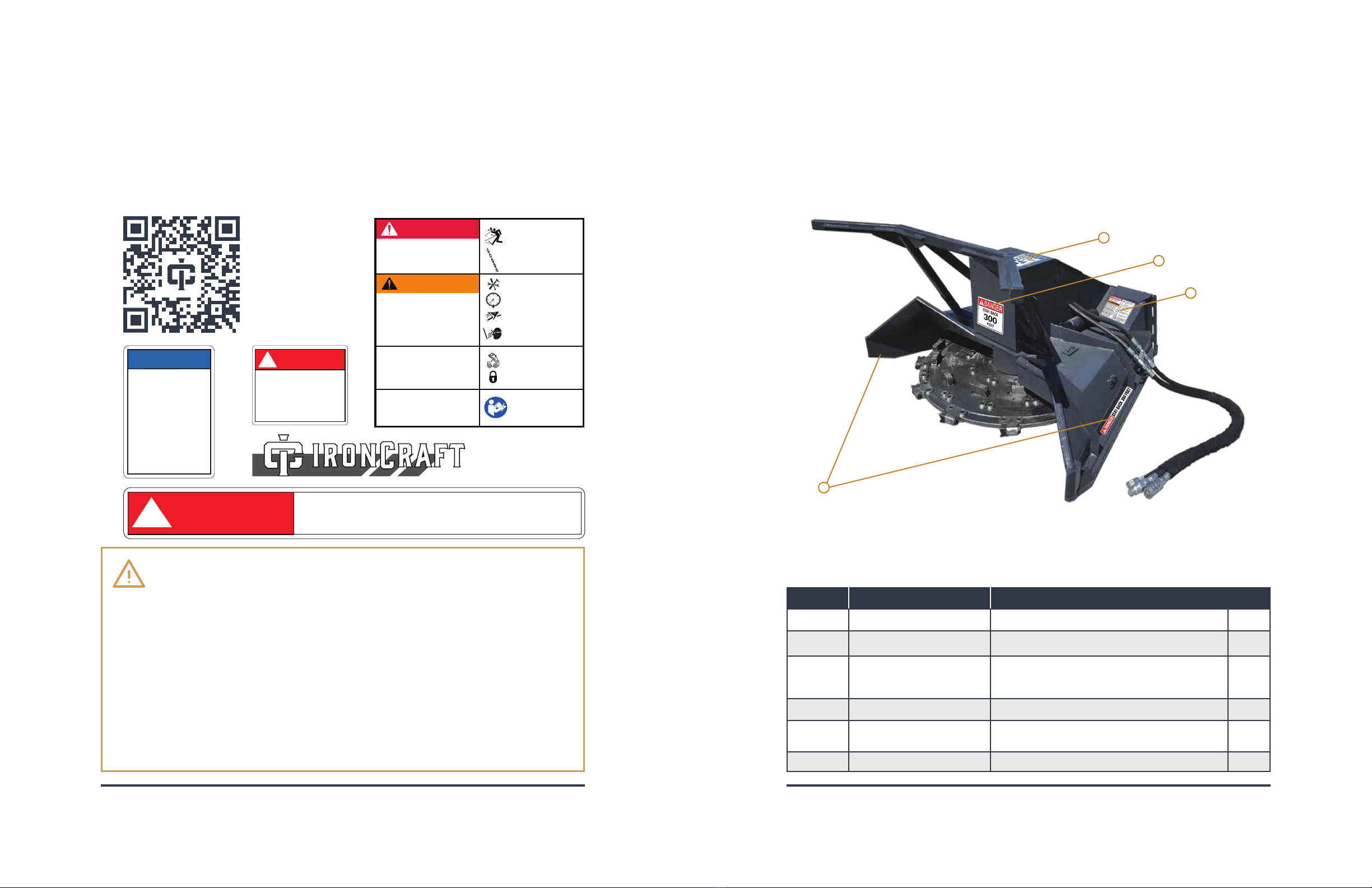
1.1 WELCOME
Congratulations on your choice of an IronCraft Forestry Disc Mulcher. This equipment has been
designed and manufactured to meet the needs of discerning users. Many features incorporated into
this disc mulcher are the result of suggestions made by customers like you.
Read this manual carefully to learn how to operate the disc mulcher safely and how to set it to provide
maximum mulching eciency. By following the operating instructions, in conjunction with a good
maintenance program, your IronCraft disc mulcher will provide many years of trouble-free service.
1.2 SAFE OPERATION
Safe, ecient, and trouble-free operation of your disc mulcher requires that you, and anyone else
who will be using or maintaining the unit, read and understand the information contained within the
Owner’s Manual. Use this manual for frequent reference and to pass on to new operators or owners.
Upon reading this manual, all users should sign the “Safety Acknowledgement Form” at the end of this
manual. Please record your model and dealer information on page 5. You will be asked to provide this
information when ordering parts or requesting service. If you need more information on this product,
contact your local dealer or visit www.ironcraftusa.com.
STORE THIS MANUAL IN THE DOCUMENT
CANISTER ATTACHED TO THIS MACHINE.
CONTENTS
Introduction . . . . . . . . . . . . . . . . . . . . . . . . . . . . . . . . . . . . . . . . . . . . . . . . . . . . . . 3
1.1 Welcome 3
1.2 Safe Operation 3
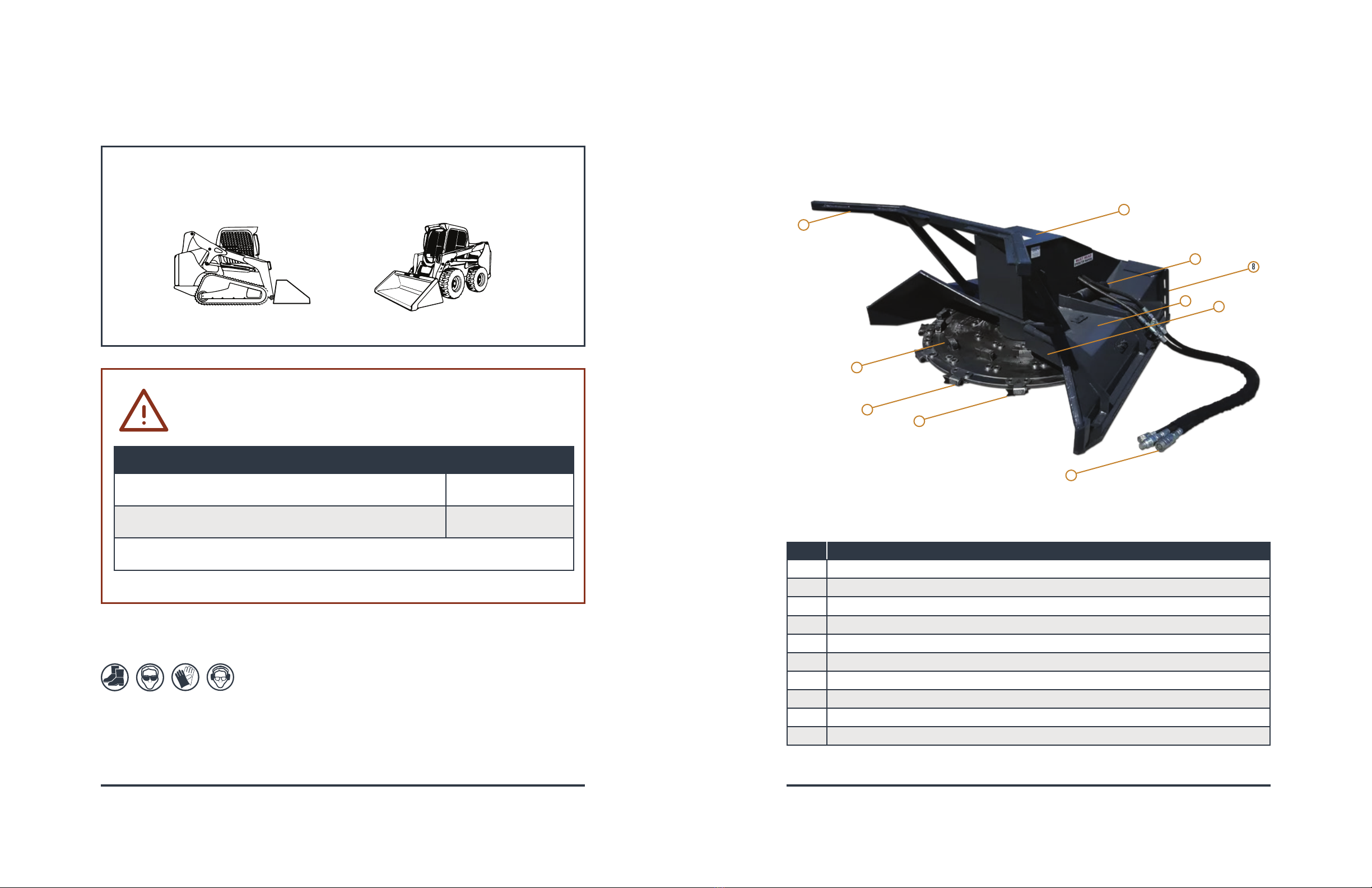
1.3 Model Comparison 4
1.4 Specications 4
1.5 Register This Product 5
Safety Information . . . . . . . . . . . . . . . . . . . . . . . . . . . . . . . . . . . . . . . . . . . . . . . . . 6
2.1 Introduction 6
2.2 Safety Alert Symbols 7
2.3 Safety Pictograms 8
2.4 General Safety Instructions 9
SAFETY SIGNS AND LABELS . . . . . . . . . . . . . . . . . . . . . . . . . . . . . . . . . . . . . . . . . . . . . 10
3.1 Safety Decals 10
3.2 Safety Sign Locations 11
3.3 Skid Steer Loader Requirements 12
Nomenclature . . . . . . . . . . . . . . . . . . . . . . . . . . . . . . . . . . . . . . . . . . . . . . . . . . . . . 13
operating procedures . . . . . . . . . . . . . . . . . . . . . . . . . . . . . . . . . . . . . . . . . . . . . . .14
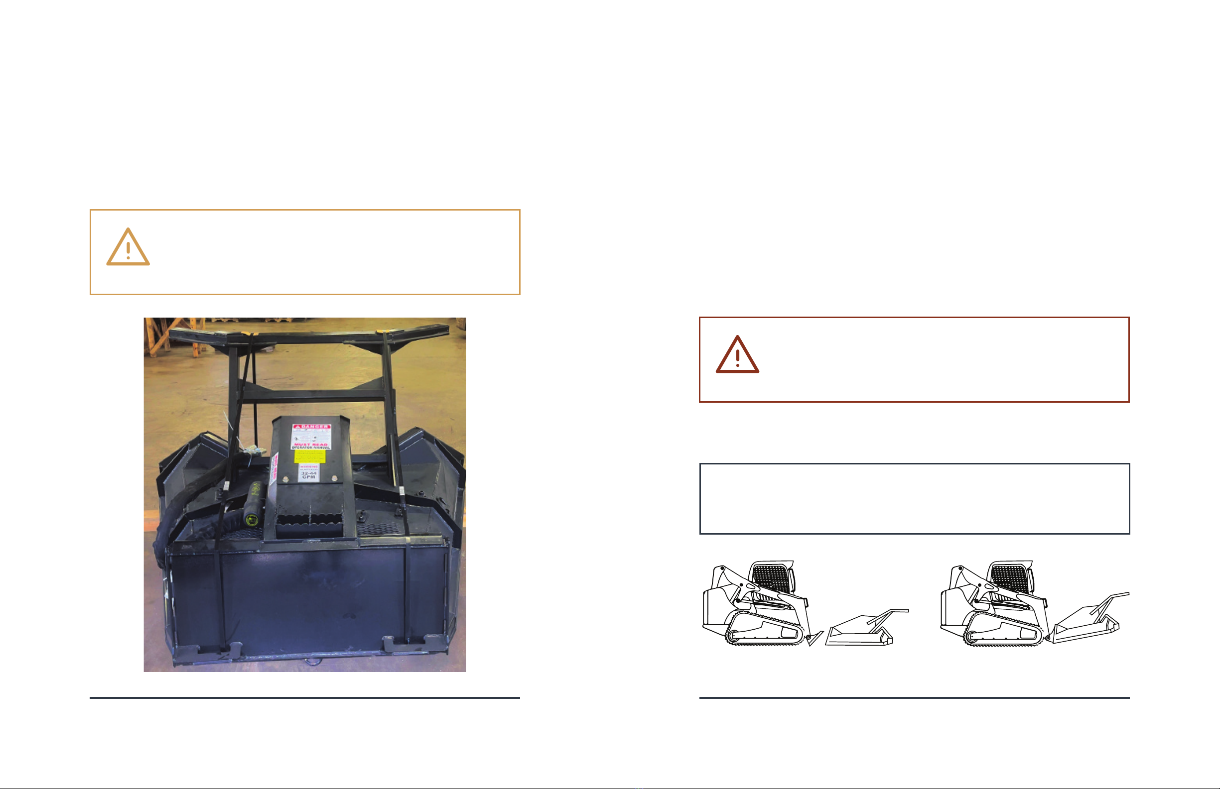
4.1 Unpacking Your Forestry Disc Mulcher 14
4.2 How To Mount Disc Mulcher 15
4.4 How To Start And Stop The Disc Mulcher 16
4.3 How To Dismount Disc Mulcher 16
4.5 Initial Use Procedure 19
4.6 General Operating Tips 21
4.7 Tree Cut Procedures 22
4.8 Tree Cutting Tips 25
Maintenance Procedures . . . . . . . . . . . . . . . . . . . . . . . . . . . . . . . . . . . . . . . . . . . . .26
5.1 Maintenance Overview 26
5.2 Maintenance Schedule 27
5.3 Storage tips 28
5.4 Mulching Disc Maintenance 29
5.5 Gear Box Maintenance 30
Troubleshooting . . . . . . . . . . . . . . . . . . . . . . . . . . . . . . . . . . . . . . . . . . . . . . . . . . .32
Parts Information 33
Limited Warranty 36
SAFETY ACKNOWLEDGEMENT FORm . . . . . . . . . . . . . . . . . . . . . . . . . . . . . . . . . . . . . . . .37
MAINTENANCE LOg . . . . . . . . . . . . . . . . . . . . . . . . . . . . . . . . . . . . . . . . . . . . . . . . . . .38
Revised September 29, 2023
©2023 IronCraft Attachments. All rights reserved.
www.ironcraftusa.com