FR
INSTRUCTIONS D’ASSEMBLAGE
Attention : Assurez-vous que toutes les vis et tous les écrous sont serrés avant l'exercice.
1
3
2
4
12
12
17
18
19
19
22
22
37
37
37
37 41
41
41
41
41
41
41
41 41
41
41
41
41
41
41
41
44
44
44
44
44
44
43
45
43
45
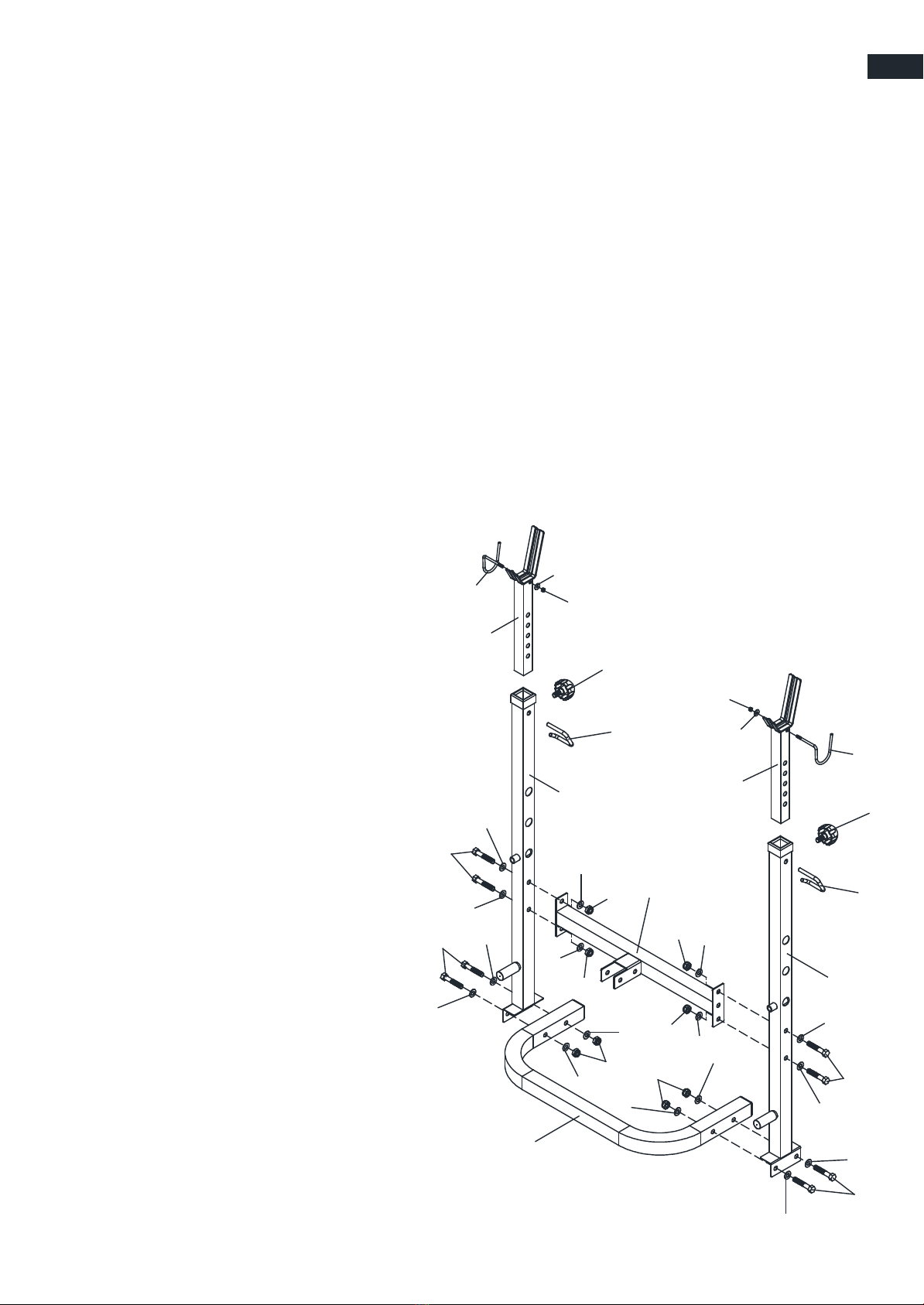
-2-
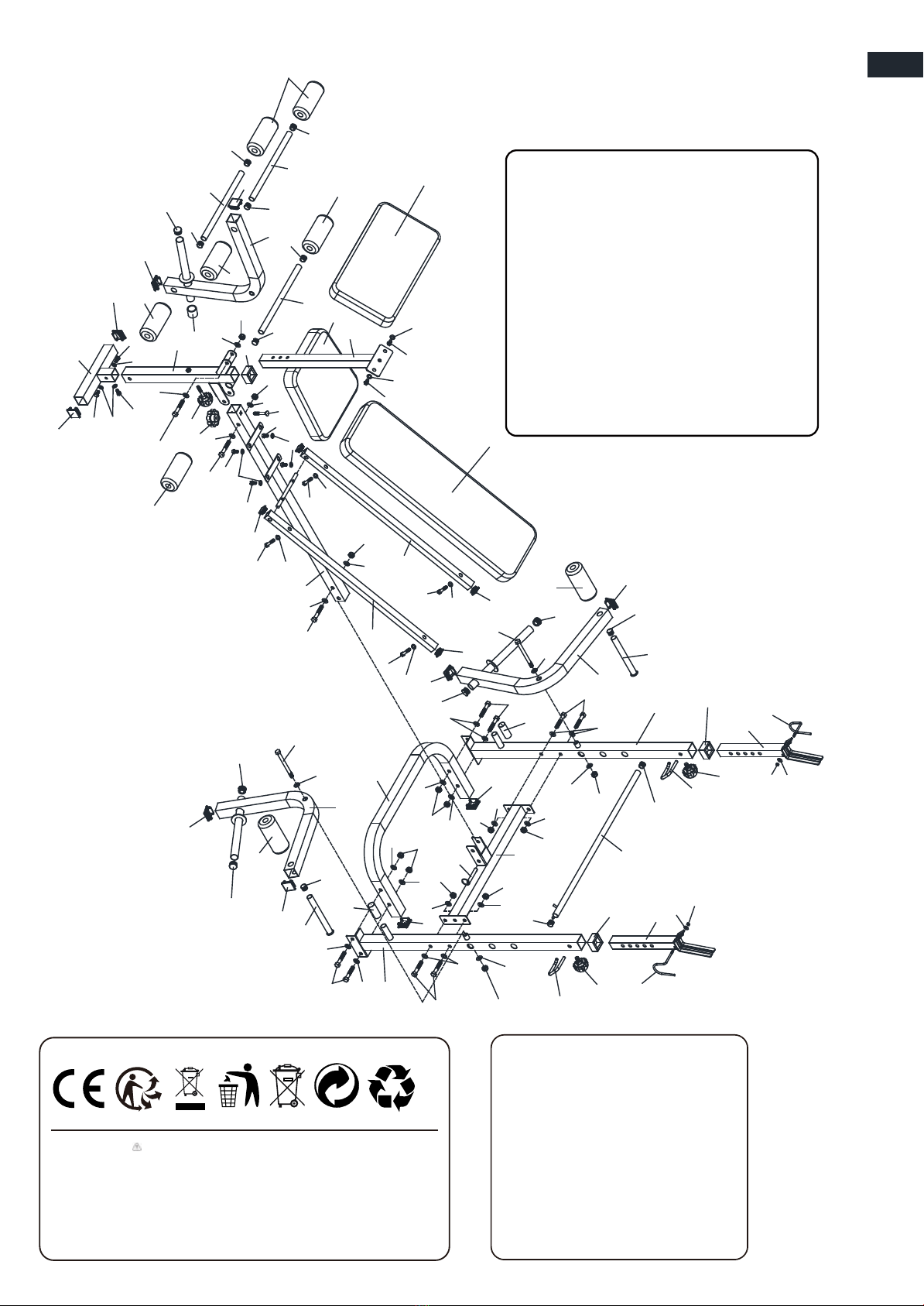
1. Fixez le montant arrière (R&L) (2&3) à la base arrière (1), en utilisant quatre boulons
hexagonaux M10X55mm (37), huit rondelles M10 (41) et quatre écrous en nylon(44).
2. Fixez le support transversal (4) au montant arrière (R&L) (2&3), à l'aide de quatre
boulons hexagonaux M10X55mm (37), huit rondelles M10 (41) et quatre écrous en
nylon M10 (44).
3. Insérez le support d'haltères (12) dans le montant arrière (R&L) (2&3), en utilisant
deux boutons de verrouillage (courts) (22) et deux crochets de sécurité (19) .
4. Fixez le crochet de sécurité (R&L) (17&18) au support d'haltères (12), en utilisant
deux rondelles M6 (43) et deux crochets
de sécurité (19).deux rondelles M6 (43)
et deux écrous en nylon M6 (45).
Étape 1 :