manuals.online logo
Brands
  1. Home
  2. •
  3. Brands
  4. •
  5. Isolite
  6. •
  7. Safety Equipment
  8. •
  9. Isolite LPX-CT User manual

Isolite LPX-CT User manual

LPX-CT
Extruded Aluminum LED Exit Sigh with Mobility Symbol
ISOLITE   WWW.ISOLITE.COM
ISOLITE HEADQUARTERS   800.888.5483   31 WATERLOO AVENUE, BERWYN, PA 19312
ISOLITE WEST   800.799.5343   3563 SUELDO SUITE M, SAN LUIS OBISPO, CA 93401
Installation Manual
READ AND FOLLOW ALL SAFETY INSTRUCTIONS
Disconnect power before performing work on electrical equipment.
Do not use outdoors.
Do not let power cords touch hot surfaces and do not mount near gas or electric heaters.
Use caution when servicing batteries. Battery acid can cause burns to skin and eyes. If acid is spilled on skin or eyes,
ush with fresh water and contact a physician immediately.
Equipment should be mounted in locations and at heights where unauthorized personnel will not readily subject it
to tampering.
The use of accessory equipment not recommended by Isolite may cause an unsafe condition, and will void the
unit’s warranty.
Do not use this equipment for other than its intended purpose.
Servicing of this equipment should be performed by qualied service personnel.
IMPORTANT SAFEGUARDS
SAVE THESE INSTRUCTIONS
Code requires that the equipment be tested every 30 days for 30 seconds, and that written records be maintained.
Further, the equipment is to be tested once a year for 90 minutes duration as per Code. The equipment is to be
repaired whenever the equipment fails to operate as intended during the duration test. Written records of test results
and any repairs made must be maintained. Isolite strongly recommends compliance with all Code requirements.
Clean exit face(s) on a regular basis.
NOTE: The servicing of any parts should be performed by qualied service personnel only. The use of replacement parts
not furnished by Isolite, may cause equipment failure and will void the warranty.
MAINTENANCE
LPX-CT
Extruded Aluminum LED Exit Sign with Mobility Symbol
ISOLITE   WWW.ISOLITE.COM
ISOLITE HEADQUARTERS   800.888.5483   31 WATERLOO AVENUE, BERWYN, PA 19312
ISOLITE WEST   800.799.5343   3563 SUELDO SUITE M, SAN LUIS OBISPO, CA 93401
Installation Manual
INSTALLATION
Wall Mount - Single Face:
1. Extend unswitched 24 hour AC supply of rated voltage to junction box or appropriate wiring (supplied by others).
Leave at least eight (8) inches of slack wire. The circuit should not be energized at this time.
2. Remove the exit sign faceplate (Figure 2).
3. Remove the exit sign universal copy kit.
4. Knock out the appropriate mounting pattern and/or wire pass-thru hole on the exit back plate to t the junction box
or wiring connector being used (supplied by others).
5. Bring wires through the back of the sign and mount the exit securely in place. Screw directly to junction box if possible.
6. Connect AC supply per diagram provided (Figure 5). Insulate unused wire!
7. CAUTION! - Failure to insulate unused wire may result in a shock hazard or unsafe condition as well as equipment
failure.
8. Route wires and secure them in place.
9. Remove any directional chevron arrows to be indicated as required from the exit stencil.
10. Remove red bre, peel back o double sided tape to secure red bre.
11. Replace the exit faceplate together with red bre.
12. Turn on the AC voltage supply.
Ceiling / End Mount - Single or Double Face:
1. Follow steps 1 to 3 of Wall Mounting instructions above.
2. If double face is required then remove the backplate cover screw and slide the backplate down and out from exit
frame. Exit signs that are specied double face will already have the second/rear faceplate installed.
3. On the top and both sides of the exit there are three (3) holes for the canopy - two (2) for the mounting screws and
one (1) wire pass-thru hole. Knock out the three appropriate canopy mounting holes for your installation (Figure 3).
4. Secure the canopy to the exit sign using the supplied 1 inch screws and washer nuts and the snap wire pass-thru hole
plastic bushing into the wire pass-thru hole in the centre of the canopy (Figure 3).
5. Bring wires through the wire pass-thru and connect AC supply as described in step 6 of Wall Mounting instructions
above.
6. Secure the exit to the wall or ceiling using the supplied 1½ inch screws and nuts. Screw directly to junction box if
possible. A universal spider plate is supplied to allow for exit sign placement adjustment or connection to a variety of
electrical boxes (Figure 4).
7. For double face exits install the second/rear faceplate.
8. Follow steps 7 to 10 of Wall Mounting instructions above.
Self-Powered:
1. For models ATX-SA, plug the battery into the circuit board per (Figure 5) self-powered sign.
SAVE THESE INSTRUCTIONS
LPX-CT
Extruded Aluminum LED Exit Sign with Mobility Symbol
ISOLITE   WWW.ISOLITE.COM
ISOLITE HEADQUARTERS   800.888.5483   31 WATERLOO AVENUE, BERWYN, PA 19312
ISOLITE WEST   800.799.5343   3563 SUELDO SUITE M, SAN LUIS OBISPO, CA 93401
Installation Manual
FIGURE 1 FIGURE 2
Face Plate
Frame
Install canopy kit as shown (if required)
Ceiling Mount
End Wall Mount
FIGURE 3
Remove chevrons / arrows as required
FIGURE 4
Universal Spiderplate
Electrical Junction Box
(Supplied by others)
FIGURE 5
SAVE THESE INSTRUCTIONS
DUAL UNIVERSAL AC SIGN SELF-POWERED SIGN
Chassis GND Chassis GND
LED Board LED Board
GREEN Ground
BLACK
105-360VAC
WHITE Neutral BLUE Neutral
BROWN
105-360VAC
Ni-Cd
Battery
24-Hours
Unswitched Supply From Generator OR
Emergency Supply
24-Hours
Unswitched Supply
GREEN Ground
BLACK
120VAC
WHITE Neutral
RED 347VAC OR
ORANGE 277VAC
AC ONLY SIGN
24-Hours
Unswitched Supply
GREEN Ground
BLACK
120VAC
WHITE Neutral
RED 347VAC OR
ORANGE 277VAC
Chassis GND
LED Board
NOTE: Cap unused AC Wire
AC ONLY SIGN
24-Hours
Unswitched Supply
GREEN Ground
BLACK
120VAC
WHITE Neutral
RED 347VAC OR
ORANGE 277VAC
Chassis GND
LED Board
NOTE: Cap unused AC Wire
PURPLE Negative
YELLOW Positive
6-24VAC
Emergency Supply
FROM Battery Pack

Other Isolite Safety Equipment manuals

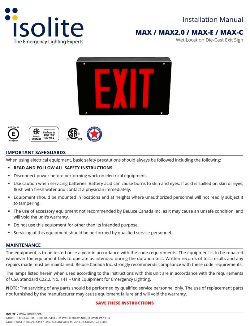
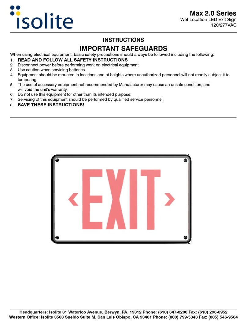
Isolite Max 2.0 Series User manual

Isolite

Isolite Max 2.0 Series User manual

Isolite MAX User manual

Isolite

Isolite MAX User manual

Popular Safety Equipment manuals by other brands

Blackline Safety G6 Getting started guide

Blackline Safety

Blackline Safety G6 Getting started guide

Yates 903 quick start guide

Yates

Yates 903 quick start guide

STRUMIN SYSTEMIC EDGE PROTECTION manual

STRUMIN

STRUMIN SYSTEMIC EDGE PROTECTION manual

Woody Valley X-ALPS manual

Woody Valley

Woody Valley X-ALPS manual

Guardian Fall Protection 10705 instruction manual

Guardian Fall Protection

Guardian Fall Protection 10705 instruction manual

Elysee 23474 manual

Elysee

Elysee 23474 manual

IKAR HWB 2,8 DW Log book and instructions for use

IKAR

IKAR HWB 2,8 DW Log book and instructions for use

FTC CHOKER JOKER LIGHT Use and maintenance instructions

FTC

FTC CHOKER JOKER LIGHT Use and maintenance instructions

3M DBI SALA ExoFit Nex 603XS1020 User instructions

3M

3M DBI SALA ExoFit Nex 603XS1020 User instructions

NSA DRIFIRE 4.4 FR quick start guide

NSA

NSA DRIFIRE 4.4 FR quick start guide

LEGRAND Arteor AR970LMWE Series quick start guide

LEGRAND

LEGRAND Arteor AR970LMWE Series quick start guide

SAFERA PCU6.3-F installation manual

SAFERA

SAFERA PCU6.3-F installation manual

ABS ABS-Lock DH06 manual

ABS

ABS ABS-Lock DH06 manual

Tractel Ballsafe Assembly instructions

Tractel

Tractel Ballsafe Assembly instructions

Dupont Tychem Vapor user manual

Dupont

Dupont Tychem Vapor user manual

U-Line S-24618 manual

U-Line

U-Line S-24618 manual

Bullard 20RT installation instructions

Bullard

Bullard 20RT installation instructions

Viking PS10 Series manual

Viking

Viking PS10 Series manual

manuals.online logo
manuals.online logoBrands
  • About & Mission
  • Contact us
  • Privacy Policy
  • Terms and Conditions

Copyright 2025 Manuals.Online. All Rights Reserved.