ITI Concord User manual

About This Manual ...............................................5
Special Installation Requirements .................5
UL-Listed Installations .............................5
UL-Canada Listed Installations ................6
California State Fire Marshall
Listed Installations ....................................6
Planning the Installation ........................................6
Standard Panel ...............................................6
SuperBus 2000 Touchpads .............................6
SuperBus 2000 RF Receivers ........................6
Power Line Carrier Card ................................7
Phone Supervision Card .................................7
Supervised Wireless Siren .............................7
SuperBus 2000 Phone Interface/Voice
Module ...........................................................7
SnapCards ......................................................7
SuperBus 2000 8Z Input
Module (HIM) ................................................7
SuperBus 2000 4-Relay Output
Module (HOM) ..............................................7
Interrogator 200 Audio
Verification Module .......................................7
Installing the System .............................................7
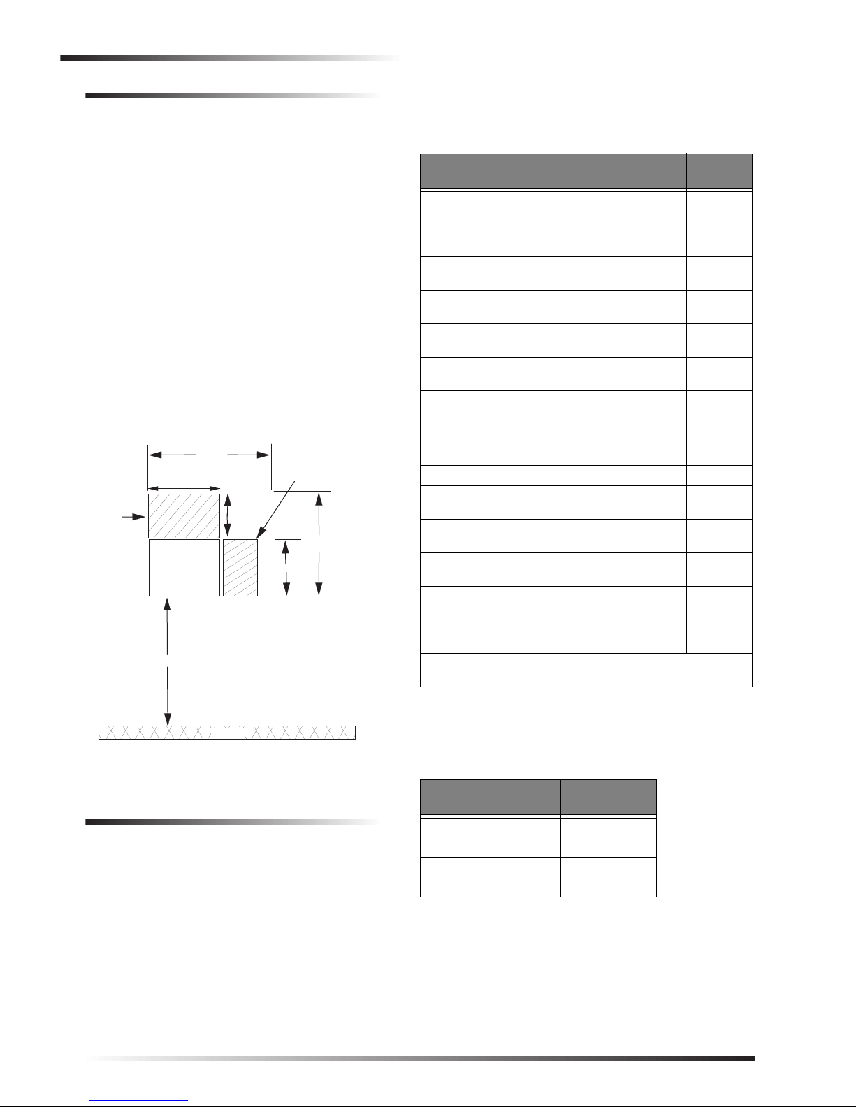
Determine the Panel Location ........................8
Total System Power and Wire Length
Guidelines ......................................................8
Mounting the Panel ........................................9
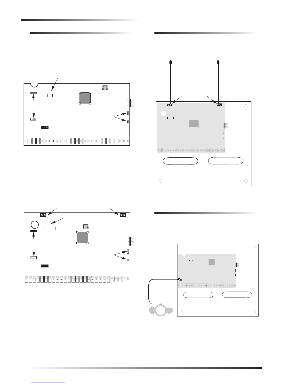
Identify Panel Components ..........................10
Installing Antennas ......................................10
Connecting the Panel to Earth Ground ........10
Installing the Optional Power Line
Carrier Card ................................................. 11
Installing the Optional Phone
Supervision Card .......................................... 11
Installing Optional SnapCards ..................... 11
Connecting Detection Devices to Panel
Zone Inputs ..................................................12
Connecting Intrusion Detection Devices 12
Connecting 2-Wire Smoke Detectors .....12
Connecting 4-Wire Smoke Detectors .....13
Connecting Speakers ....................................13
15-Watt Speaker ......................................14
Hardwire Interior Speaker ......................14
Connecting Piezo Sirens ..............................14
Exterior Sirens ........................................15
Interior Sirens .........................................15
Installing Supervised
Wireless Sirens .............................................15
Connecting an Interrogator 200
Audio Verification Module ..........................16
Connecting Alphanumeric and
Fixed Display Touchpads .............................16
Installing SuperBus 2000 Modules ..............17
SuperBus 2000 RF Receiver
(60-764-01-95R-16Z/32Z/MAX) ...........17
SuperBus 2000 Phone
Interface/Voice Module............................18
Energy Saver Module...............................19
SuperBus 2000 8Z Input Module.............19
4-Relay Output Module ..........................20
Setting Device Address on SuperBus
2000 Devices ................................................20
Installing an RJ-31X Phone Jack .................20
Connecting the Phone Line to the
Panel with a DB-8 Cord ...............................21
Connecting the AC Power Transformer .......21
Powering Up the Panel .................................22
Programming the Panel .......................................22
Entering Program Mode ...............................22
Touchpad Button Programming Functions ..23
Moving Through Program Mode
Tiers and Menus ...........................................23
Programming Tier 1 Menu Items .................24
Programming Tier 2 Menu Items .................24
Using Shortcut Numbers .........................25
Security Menu .........................................25
Phones Menu ...........................................27
Phone Options Menu ...............................30
Timers Menu ...........................................34
Light Control Menu ................................36
Touchpad Options Menu .........................36
Reporting Menu ......................................37
Siren Options Menu ................................41
Sensors Menu ..........................................42
Audio Verification Menu ........................44
Accessory Modules Menu .......................45
Onboard Options Menu ...........................48
Exiting Programming Mode .........................50
Entering User Programming Mode ..............50
Time and Date Menu ...............................50
User Codes Menu ....................................50
Options Menu ..........................................52
Set Up Schedules Menu ..........................53
Attach Schedules to Events Menu ..........53
Energy Saver Menu .................................55
Attach Lights to Sensors Menu ...............55
System Version Menu .............................55
Downloader Programming ...........................56
ToolBox Downloader Programming .......56
Document No. 466-1512-01 August 2, 2000
Preliminary
Installation Instructions
This document describes the installation, programming, testing,
and troubleshooting procedures for installing Concord 2.0 secu-
rity systems.

DRAFT 8/17/00
Installation Instructions
Testing the System ...............................................56
Basic System Commands .............................56
Testing Zones/Sensors ..................................56
If a Wireless Sensor Does Not Test .........57
Testing Phone Communication .....................57
Testing Central Station/Pager
Communication ............................................57
Testing Outputs and Sirens ...........................58
Testing Light Control ...................................58
Testing the Energy Saver Module (ESM) ....58
Changing Fixed Display LCD
Touchpad Chime and Trouble Beep Tones ...59
Testing Audio Verification Module (AVM)
Communication ............................................59
Troubleshooting ...................................................61
Appendix A: System Planning Worksheets .........69
Appendix B: Reference Tables ............................74
Appendix C: Reference Tables ............................77
Programming Mode Menus and Settings ............81
System Wiring Notes ...........................................87
Index ....................................................................89

Notices
FCC Part 15 Information to the User
Changes or modifications not expressly approved by Interactive Technologies, Inc. can void the user’s authority to operate the equipment.
FCC Part 15 Class A (Commercial)
This equipment has been tested and found to comply with the limits for a class A digital device, pursuant to part 15 of the FCC rules. These limits are designed to provide
reasonable protection against harmful interference when the equipment is operated in a commercial environment.
This equipment generates, uses,and can radiate radio frequency energy and, if not installed and used in accordance with the instruction manual, may cause harmful interference
to radio communications. Operation of this equipment in a residential area is likely to cause harmful interference in which case users will be required to correct the interference
at their own expense.
FCC Part 15 Class B (Residental)
This equipment has been tested and found to comply with the limits for a Class B digital device, pursuant to part 15 of the FCC Rules. These limits are designed to provide
reasonable protection against interference in a residential installation.
This equipment generates, uses, and can radiate radio frequency energy and, if not installed and used in accordance with the instructions, may cause harmful interference to
radio communications. However, there is no guarantee that interference will not occur in a particular installation.
If this equipment does cause harmful interference to radio or television reception, which can be determined by turning the equipment off and on, the user is encouraged to try
to correct the interference by one or more of the following measures:
• Install a quality radio or television outdoor antenna if the indoor antenna is not adequate.
• Reorient or relocate the panel.
• Move the panel away from the affected equipment.
• Move the panel away from any wire runs to the affected equipment.
• Connect the affected equipment and the panel to separate outlets, on different branch circuits.
• Consult the dealer or an experienced radio/TV technician for help.
• Send for the FCC booklet How to Identify and Resolve Radio-TV Interference Problems, available from the U.S. Government Printing Office, Washington, D.C.
20402. Stock Number: 004-000-00345-4.
FCC Part 68
This equipment complies with Part 68 of the FCC Rules. Located on this equipment is a label that contains, among other information, the FCC registration number and the
ringer equivalence number (REN) for this equipment. If requested, this information must be provided to the telephone company.
The REN is used to determine the maximum number of devices that may be connected to your telephone line. In most areas, the sum of all device RENs should not exceed five
(5.0).
If this equipment causes harm to the telephone network, the telephone company may temporarily disconnect your service. If possible, you will be notified in advance. When
advance notice is not practical, you will be notified as soon as possible. You will also be advised of your right to file a complaint with the FCC.
Your telephone company may make changes in its facilities, equipment, operations, or procedures that could affect the proper operation of your equipment. You will be given
advanced notice in order to maintain uninterrupted service.
If you experience trouble with this equipment, please contact
Interactive Technologies, Inc.
2266 Second Street North
North Saint Paul, MN 55109
1-800-777-1415
This equipment may not be used on coin service provided by the telephone company. Connection to party lines is subject to state tariffs.
Declaration of Conformity (DoC)
Interactive Technologies, Inc. declares that the ITI model no. 60-792-95R is in conformity with Part 15 of the FCC Rules. Operation of this product is subject to the following
two conditions: (1) This device may not cause harmful interference, and (2) this device must accept any interference received, including interference that may cause undesired
operation.

Canada Notice
The Canadian Department of Communications label identifies certified equipment. This certification means that the equipment meets certain telecommunications network pro-
tective, operational, and safety requirements. The department does not guarantee the equipment will operate to the user’s satisfaction.
Before installing this equipment, users should ensure that it is permissible to be connected to the facilities of the local telecommunications company. The equipment must also
be installed using an acceptable method of connection. In some cases, the company’s inside wiring associated with a single-line individual service may be extended by means
of a certified connector assembly (telephone extension cord). The customer should be aware that compliance with the above conditions may not prevent degradation of service
in some situations.
Repairs to certified equipment should be made by an authorized Canadian maintenance facility designated by the supplier. Any repairs or alterations made by the user to this
equipment, or equipment malfunctions, may give the telecommunications company cause to request the user to disconnect the equipment.
For your protection, make sure that the electrical ground connections of the power utility, telephone lines, and internal metallic water pipe system, if present, are connected
together.
Caution
Do not attempt to make connections yourself. Contact the appropriate electrician or electric inspections authority.
The Load Number (LN) assigned to each terminal device denotes the percentage of the total load to be connected to a telephone loop that is used by the device to prevent
overloading. The termination on a loop may consist of any combination of devices subject only to the requirement that the total of the LNs of all the devices does not exceed
100. Load Number: 0.2B AC
“AVIS: - L ´étiquette du ministère des Communications du Canada identifie le matériel homologué. Cette étiquette certifie que le matériel est conforme a certaines normes de
protection, d ´ exploitation et de sécurité des réseaux de télécommunications. Le ministère n ´ assure toutefois pas que le matériel fonctionnera a la satisfaction de l ´ utilisateur.
Avant d ´ installer ce matériel, l ´ utilisateur doit s ´ assurer qu´ il est permis de le raccorder aux installations de l ´ enterprise locale de télécommunication. Le matériel doit
également etre installé en suivant une méthod acceptée de raccordement. Dans certains cas, les fils intérieurs de l´ enterprise utilisés pour un service individuel a ligne unique
peuvent etre prolongés au moyen d´ un dispositif homologué de raccordement (cordon prolongateur téléphonique interne). L ´ abonné ne doit pas oublier qu ´ il est possible
que la conformité aux conditions énoncées ci-dessus n ´ empechent pas le dégradation du service dans certaines situations. Actuellement, les enterprises de télécommunication
ne permettent pas que l ´ on raccorde leur matériel a des jacks d ´ abonné, sauf dans les cas précis prévus pas les tarrifs particuliers de ces enterprises.
Les réparations de matériel homologué doivent etre effectuées pas un centre d ´ entretien canadien autorisé désigné par le fournisseur. La compagne de télécommunications
peut demander a l ´ utilisateur de débrancher un appareil a la suite de réparations ou de modifications effectuées par l ´ utilisateur ou a cause de mauvais fonctionnement.
Pour sa propre protection, l ´ utilisateur doit s ´ assurer que tous les fils de mise a la terre de la source d ´ énergie électrique, des lignes téléphoniques et des canalisations d ´´
eau métalliques, s ´ il y en a, sont raccordés ensemble. Cette précaution est particulièrement importante dans les régions rurales.
Avertissment. - L ´ utilisateur ne doit pas tenter de faire ces raccordements lui-meme; il doit avoir recours a un service d ´ inspection des installations électriques, ou
a electricien, selon le cas”.
Une note explicative sur les indices de charge (voir 1.6) et leur emploi, a l ´ intention des utilisateurs du matériel terminal, doit etre incluse dans l ´ information qui accompagne
le materiel homologué. La note pourrait etre rédigée selon le modèle suivant:
“L ´ indice de charge (IC) assigné a chaque dispositif terminal indique, pour éviter toute surcharge, le pourcentage de la charge totale qui peut etre raccordée a un circuit télé-
phonique bouclé utilisé par ce dispositif. La terminaison du circuit bouclé peut etre constituée de n ´ import somme des indices de charge de l ´ ensemble des dispositifs ne
dépasse pas 100.”
L ´ Indice de charge de cet produit est ____________.
Trademarks
ITI, SuperBus, and ITI ToolBox are registered trademarks of Interactive Technologies, Inc. Concord and SnapCard are trademarks of Interactive Technologies, Inc. X-10 is
a registered trademark of X-10 (USA), Inc.
This manual may refer to products that are announced but are not yet available.
651/777-2690
651/779-4890

5
DRAFT 8/17/00
About This Manual
About This Manual
This manual provides information for planning, installing, pro-
gramming, and testing this security system. When necessary,
this manual refers you to other documentation included with
compatible peripherals.
Planning sheets are included for you to record hardware layout
and software programming settings.
About the User’s Manual
The User’s Manual (466-1513-01) contains user worksheets
that should be filled out during the installation and program-
ming of the system. With two partition systems, a User’s
Manual for each partition is suggested.
Special Installation Requirements
This security system can be used as a fire warning system, an
intrusion alarm system, an emergency notification system, or
any combination of the three.
Some installations may require configurations dictated by city/
state codes, insurance, or Underwriter’s Laboratories (UL).
This section describes the various component and configura-
tion listings.
UL Listed Installations
This section describes the requirements for UL Listed installa-
tions.
Basic System
❑Control Panel (60-734-01 or 60-792-01-95R)
❑Backup Battery 12V 4 AH (60-681) or 12V 7 AH (60-
680)
❑SuperBus 2000 Fixed Display Touchpad (60-820), 2x16
LCD Touchpad (60-746-01), 2x20 LCD Touchpad (60-
803), or VFD Touchpad (60-804)
❑Standard Class II 24 VAC, 30 VA Power Transformer
(60-761), Class II 24 VAC, 30 VA Line Carrier Power
Transformer (60-762), or Standard Class II 24 VAC, 50
VA Power Transformer (60-778), Class II 24 VAC, 50 VA
Line Carrier Power Transformer (60-779)
❑Interior Speaker Siren (60-528), Exterior Speaker Siren
(13-060), Slim Line Hardwire Interior Siren (60-483-01)
or Hardwire Exterior Siren (13-046)
Basic system may also include a SuperBus 2000 RF Receiver
(60-764-01-95R-16Z) or (60-764-01-95R-32Z) or
(60-764-01-95R-MAX).
Household Burglary Alarm System Unit (UL 1023)
Basic system, plus:
❑Hardwire Magnetic Contact (13-068 or 13-071) or
Wireless Learn Mode Door/Window Sensor (60-362)
❑IMMEDIATE TROUBLE BEEPS set to on
❑UL 98 OPTIONS set to on (see page 41)
❑RECEIVER FAILURE set to on (if wireless devices are
used)
❑SIREN VERIFY set to on
❑EXIT DELAY set to 60 seconds
❑QUICK EXIT set to off
❑EXIT EXTENSIONset to off
❑SIREN TIMEOUT set to 4 minutes or more
❑ENTRY DELAY set to 45 seconds or less
❑AC FAILURE set to on
❑RF TX TIMEOUT set to 24 hours (if system includes a
built in or SuperBus 2000 RF Receiver and wireless
smoke sensors)
Household Fire Warning System (UL 985)
Basic system, plus:
❑Hardwire Smoke Detector:
System Sensor models 2100D, 2100TD, 2100S, 2100TS,
2400, or 2400TH learned into sensor group 26 or
Sentrol (ESL) models 429AT, 521B or 521BXT learned
into sensor group 26
❑Wireless Smoke Sensor 60-506-319.5 or 60-838-95
learned into sensor group 26
❑IMMEDIATE TROUBLE BEEPS set to on
❑UL 98 OPTIONS set to on (see page 41)
❑RECEIVER FAILURE set to on
❑SIREN VERIFY set to on
❑AC FAILURE set to on
❑RF TX TIMEOUT set to 4 hours (if system includes a
built in or SuperBus 2000 RF Receiver and wireless
smoke sensors)
UL 1023 & 985 24-Hour Backup
❑For 24-hour backup, the total current draw for all con-
nected devices is limited to 90 mA (during normal standby
conditions) using a 4.0 AH battery, or 190 mA (during
normal standby conditions) using a 7.0 AH battery.
Commercial Burglary Alarm System Unit
(Grade C UL 1610)
Basic system using Control Panel 60-801-01 plus:
❑Hardwire Magnetic Contact (13-068 or 13-071) or Wire-
less Learn Mode Door/Window Sensor (60-499)
❑ITI SAW PIR Sensor (60-639-95R), ITI Crystal PIR Sen-
sor (60-703-95R), or DS924i PIR Sensor (60-511-01-95)
❑IMMEDIATE TROUBLE BEEPS set to on
❑UL 98 OPTIONS set to on (see page 41)
❑RECEIVER FAILURE set to on (if wireless devices are
used)
❑RF TX TIMEOUT set to 4 hours
❑24-HOUR TAMPER set to on
❑SYSTEM TAMPER set to on
❑AUTO PHONE TEST set to on
❑PHONE TEST FREQ. set to 1
❑NEXT PHONE TEST set to 1
❑SIREN VERIFY set to on
❑AC FAILURE set to on
UL 1610 24-Hour Backup
❑Same as UL 1023 & 985
UL 1635 Digital Alarm Communicator System
❑Same as UL 1023 & 985

6DRAFT 8/17/00
Planning the Installation
Central Station Reporting
The panel has been tested with the following central station
receivers using SIA and Contact ID reporting formats:
❑ITI CS-5000 Central Station Receiver
❑Sur-Gard Central Station Receiver with models
SG-DRL2A and SG-CPM2
❑AC FAILURE set to on
UL Canada Listed Installations
This section describes the requirements for CUL (UL Canada)
Listed installations.
Canadian Standards CSA Certified Accessories
Residential Burglary Alarm System Unit
(ULC-S309)
Basic system as described for “UL Listed Installations” plus:
❑Hardwire Magnetic Contact (13-068 or 13-071) or Wire-
less Learn Mode Door/Window Sensor (60-362)
Residential Fire Warning System Control Unit
(ULC-S545-M89)
Basic system as described for “UL Listed Installations” plus:
❑Hardwire Smoke Detector:
System Sensor models 2100D, 2100TD, 2100S, 2100TS,
2400, 2400TH learned into Sensor Group 26, or
Sentrol (ESL) models 429AT, 521B, or 521BXT learned
into sensor group 26
❑Wireless Smoke Sensor 60-506-319.5 or 60-838-95
learned into sensor group 26
❑IMMEDIATE TROUBLE BEEPS set to on
❑RF TX TIMEOUT set to 4 hours (if system includes
SuperBus 2000 RF Receiver and wireless smoke sensors)
Note
For 24-hour backup, external power drain is limited to
90 mA (during normal standby condition) using a 4.0
AH battery, or 190 mA continuous using a 7.0 AH bat-
tery.
California State Fire Marshall Listed Installations
Same as Household Fire Warning System (UL 985), plus:
❑SMOKE VERIFY must be set to off
Planning the Installation
This section describes system capabilities to help you get
familiar with the system. “Appendix A” provides planning
sheets with tables that let you record the hardware and pro-
gramming configuration of the system. Fill in all necessary
information ahead of time to help prepare for system installa-
tion.
When planning the installation, keep in mind that the panel has
the following capabilities (dependent upon devices used):
❑Up to 16 SuperBus 2000 Devices
❑Up to 76 wireless or hardwired zones
Standard Panel
The following describe the basic panel (out-of-box) hardware
capabilities.
❑Power: Input for an AC step-down, plug-in style trans-
former.
❑Auxiliary Power Output: Output that supplies 8.5 to
13.5 VDC with up to 1 amp (with panel powered by 30
VA transformer) or 2 amps (with panel powered by 50 VA
transformer) for bus devices and hardwired detectors, such
as smoke and motion detectors.
❑Bus A and B: Input and output that provides communica-
tion between bus devices and the panel.
❑Siren Driver: Output that can drive an 8-ohm load and
provides intrusion and fire alarm sounds for partition 1.
❑2 Onboard Outputs: Open-collector outputs that can be
set up to activate other signalling devices, based on sys-
tem events.
❑Microphone Input: Input used for 2-way audio when
used in conjunction with the Interrogator 200 Audio Veri-
fication Module.
❑8 Supervised Hardwire Zones: Inputs for various hard-
wired detectors. Zone 8 can be set up in programming to
accept 2-wire smoke detectors.
❑Built-In SuperBus 2000 Receiver
(60-792-01-95R only): Allows use of up to 16 or 32 ITI
319.5 MHz. crystal and/or SAW Learn Mode wireless
sensors and touchpads. Also allows supervision of Super-
vised Wireless Sirens.
❑Phone Line Connection: Allows panel to communicate
with central monitoring station and/or pagers.
SuperBus 2000 Touchpads
The following describes the different touchpads that can be
used for system programming and operation.
❑SuperBus 2000 Fixed Display Touchpad: Provides oper-
ation control and user-programming access (not installer/
dealer programming). Displays system messages and
indicates system status.
❑SuperBus 2000 2x16 LCD Touchpad: Provides com-
plete system programming and operation control. Dis-
plays system messages that prompt users for information
when needed and indicates system status.
❑SuperBus 2000 2x20 LCD Touchpad: Provides com-
plete system programming and operation control. Large
display shows system messages that prompt users for
information when needed and indicates system status.
❑SuperBus 2000 2x20 VFD Touchpad: Provides complete
system programming and operation control. Large fluores-
cent display shows system messages that prompt users for
information when needed and indicates system status.
SuperBus 2000 RF Receivers
These receivers expand system wireless zone capacity by 16,
32, or the maximum zones allowed by the panel. The receivers
are compatible with all ITI 319.5 MHz. crystal and SAW Learn
Mode wireless sensors, touchpads, and Supervised Wireless
Sirens.

7
DRAFT 8/17/00
Installing the System
Power Line Carrier Card
Adding this card (which requires that the panel be powered
using a Power Line Carrier Transformer) adds the following
capabilities to the system:
❑Allows the use of Supervised Wireless Sirens.
❑Allows the use of X-10 Powerhouse Lamp Modules for
light control and light activation during alarms.
Phone Supervision Card
Adding this card allows the panel to check for the correct
phone line voltage (partition 1 only), upon dialing the central
station/pager number. The panel can also be programmed to
check the phone line voltage automatically.
Supervised Wireless Siren
Supervised Wireless Sirens plug into any standard electrical
outlet and produce status and alarm sounds. The panel sends
signals to the siren through the Power Line Carrier Card and
Line Carrier Power Transformer, through the AC electrical
wiring.
The siren has a built-in transmitter that is used for supervising
with the panel. With the siren transmitter learned into panel
memory (panels with receivers), the siren can notify the panel
if it is unplugged, stops receiving panel signals, or has a low
backup battery.
SuperBus 2000 Phone Interface/Voice
Module
This module allows system access and control using touch-
tone telephones, on- or off-site. The module includes an output
for a speaker that sounds system status and alarm voice mes-
sages.
SnapCards
The following SnapCards expand the system as described:
❑8Z Input SnapCard: Provides eight additional hardwire
zone inputs, of which two are dedicated for using 2-wire
smoke detectors.
❑4 Output SnapCard: Provides four form C relay outputs
that can be set up to activate other signalling devices,
based on system events, schedules, or direct control.
❑4Z Input/2 Output Combo SnapCard: Provides three
hardwire zone inputs, one two wire smoke detector loop,
and two outputs that can be set up to activate other signal-
ling devices, based on system events, schedules, or direct
control.
SuperBus 2000 8Z Input
Module (HIM)
Provides eight additional hardwire zone inputs.
SuperBus 2000 4-Relay Output Module
(HOM)
Provides four form C relay outputs that can be set up to acti-
vate other signalling devices, based on system events.
Interrogator 200 Audio
Verification Module
Adding this module allows central station operators to listen-in
and talk to occupants on the premises, to verify the emergency
when an alarm report is received.
Installing the System
This section describes how to install the system control panel.
Before starting the installation, plan your system layout and
programming using the worksheets provided in Appendix A.
Installing the system consists of the following:
❑Determining the Panel Location
❑Total System Power and Wire Length Guidelines
❑Mounting the Panel
❑Identifying Panel Main Components
❑Installing the Optional Power Line Carrier Card
❑Installing Optional SnapCards
❑Connecting Detection Devices to Panel Zone Inputs
❑Connecting Speakers
❑Connecting Piezo Sirens
❑Connecting an Interrogator 200 Audio Verification
Module
❑Connecting Alphanumeric and Fixed Display Touchpads
❑Installing SuperBus 2000 Modules
❑Installing an RJ-31X Phone Jack
❑Connecting the Phone Line to the Panel with a DB-8 Cord
❑Connecting the AC Power Transformer
❑Powering Up the Panel

8DRAFT 8/17/00
Installing the System
Determine the Panel Location
Before permanently mounting the panel, determine panel loca-
tion using the following guidelines:
❑Centrally locate the panel with relation to detection
devices whenever possible, to help reduce wire run
lengths and labor.
❑Locate the panel where the temperature will not exceed
120°F (49°C) or fall below 32°F (0°C).
❑Avoid running wires parallel with electrical wiring or fix-
tures such as fluorescent lighting, to prevent wire runs
from picking up electrical noise.
❑Mount the panel at a comfortable working height (about
45 to 55 inches from the floor to the bottom of the panel,
as shown in Figure 1).
❑Leave space to the left and right of the panel for wiring,
phone jack, and mounting optional modules.
❑For wireless panels or hardwire panels that include a
SuperBus 2000 RF Receiver, allow at least 9 inches above
the panel cabinet for antennas.
❑Allow at least 24 inches in front of the panel to open the
panel door.
Figure 1. Determining Panel Location
Total System Power and Wire Length
Guidelines
The panel can supply up to 1 amp (1,000 mA) when powered
by the 24 VAC, 30 VA transformer or up to 2 amps (2,000 mA)
when powered by the 24 VAC, 50 VA transformer for system
devices.
The total system wire length allowed can vary depending on
devices powered by the panel, the wire length between devices
and the panel, and the combined wire length of all devices.
Table 1 describes the maximum wire length allowed between
compatible devices and the panel, including the maximum cur-
rent draw of each device.
Table 2 describes the total system wire lengths allowed when
installing systems using unshielded or shielded cable.
PANEL
19.25"
12"
12"
21"
45-55"
PHONE JACK AND
OPTIONAL MODULE
MOUNTING AREA
ANTENNA
AREA
NOTE
ALLOW AT LEAST 24"
IN FRONT OF PANEL
TO ALLOW FOR OPENING
CABINET DOOR AND
ACCESS TO PANEL
COMPONENTS.
9"
FLOOR
Table 1. Maximum Device Wire Length and Current Draw
Device Max. Wire
Length to Panel Max. mA
Draw
SuperBus 2000 2x16 LCD
Alphanumeric Touchpad 22 ga.—300 ft.
18 ga.—750 ft. 90 mA
SuperBus 2000 2x20 LCD
Alphanumeric Touchpad 22 ga.—250 ft.
18 ga.—600 ft. 120 mA
SuperBus 2000 2x20 VFD
Alphanumeric Touchpad 22 ga.—250 ft.
18 ga.—600 ft. 120 ma
SuperBus 2000 Fixed Dis-
play Touchpad 22 ga.—300 ft.
18 ga.—700 ft. 65 mA
SuperBus 2000 RF Receiver 22 ga.—1,100 ft.
18 ga.—2,800 ft. 30 mA
SuperBus 2000 Phone Inter-
face/Voice Module 22 ga.—40 ft.
18 ga.—120 ft. 600 mA
Power Line Carrier Card N/A 110 mA
4 Input/2 Output SnapCard N/A 185 mA*
8Z Hardwire Zone Expander
SnapCard N/A 230 mA*
4 Output SnapCard N/A 130 mA*
SuperBus 2000 8Z Input
Module 22 ga.—1,800 ft.
18 ga.—4,500 ft. 35 mA
SuperBus 2000 4-Relay Out-
put Module 22 ga.—350 ft.
18 ga.—900 ft. 180 mA
SuperBus 2000 Energy
Saver Module 22 ga.—1,600 ft.
18 ga.—4,000 ft. 20 mA
Interrogator 200 22 ga.—3,200 ft.
18 ga.—4,500 ft. 10 mA
Interrogator AVM 22 ga.—110 ft.
18 ga.—260 ft. 300 mA
*Maximum current draw for the SnapCards does not include
the load which may be applied to their auxiliary DC supply.
Table 2. Total System Wire Length
Allowed
Wire Type Total System
Wire
22-gauge, unshielded
22-gauge, shielded
4,500 ft.
3,000 ft.
18-gauge, unshielded
18-gauge, shielded
3,500 ft.
2,200 ft.

9
DRAFT 8/17/00
Installing the System
Table 3 describes the minimum current draw of each device
when the panel is operating only from the backup battery. For
24-hour backup, the total current draw of all SnapCards
connected to the panel and devices connected to +12 BUS
(panel terminal 4) is limited to 90 mA (during normal standby
condition) using a 4.0 AH battery, or 190 mA (during normal
standby condition) using a 7.0 AH battery.
After determining panel location, run all necessary wires to
that location using the guidelines in Table 4.
Mounting the Panel
Use the following procedure to mount the panel to the wall or
wall studs.
CAUTION
Make sure you are free of static electricity whenever
you work on the panel with the cover open. To dis-
charge any static, first touch the metal panel chassis,
thenstay in contact withthe chassis when touching the
circuit board. Using an approved grounding strap is
recommended.
To mount the panel:
1. Open the panel door and remove the necessary wiring
knockouts (see Figure 2). Be careful not to damage the
circuit board.
2. Feed all wires through wiring knockouts and place the
panel in position against the wall.
3. Level the panel and mark the top and bottom mounting
holes (see Figure 2).
4. Install anchors where studs are not present.
5. Partially insert screws into the two top mounting hole
locations, then hang the panel on the two screws.
6. Recheck for level, insert the two lower screws, and tighten
all four mounting screws.
Figure 2. Mounting the Panel (Hardwire Panel Shown—
Combination Hardwire/Wireless Panel
Similar)
Table 3. Minimum Device Current Draw
Device Min. mA
Draw
SuperBus 2000 2x16 LCD Alphanumeric
Touchpad 15 mA
SuperBus 2000 2x20 LCD Alphanumeric
Touchpad 15 mA
SuperBus 2000 2x20 VFD Alphanumeric
Touchpad 15 mA
SuperBus 2000 Fixed Display Touchpad 11 mA
SuperBus 2000 RF Receiver 27 mA
SuperBus 2000 Phone Interface/Voice Module 25 mA
Power Line Carrier Card N/A
4 Input/2 Output SnapCard 20 mA
8Z Hardwire Zone Expander SnapCard 38 mA
4 Output SnapCard 1 mA
SuperBus 2000 8Z Input Module 18 mA
SuperBus 2000 4-Relay Output Module 12 mA
SuperBus 2000 Energy Saver Module 20 mA
Interrogator 200 10 mA
Interrogator AVM 45 mA
Table 4. Device Wiring Requirements
Device Wire Requirements
AC Power Transformer 2-conductor, 18-gauge, 25 feet
maximum
Earth Ground Single conductor, 16-gauge
solid, 25 feet maximum
Telephone (RJ-31X) 4-conductor
Detection Devices 2- or 4-conductor, 18- to 22-
gauge, 300 ohms maximum
loop resistance including device
Speakers 2-conductor, 22-gauge, 175 feet
maximum
2-conductor, 18-gauge, 440 feet
maximum
SuperBus 2000 Devices 4-conductor, 22- or 18-gauge
Interrogator 200 AVM
Power and Microphone 4-conductor, 22-gauge, shielded
2-Wire Smoke Detectors 2-conductor, 22-gauge, 330 feet
maximum
2-conductor, 18-gauge, 830 feet
maximum
(based on 10 ohms maximum
loop resistance plus a 2k-ohm,
end-of-line resistor)
Table 4. Device Wiring Requirements
Device Wire Requirements
8573126A.DS
F
M OUNTING HOLES
M OUNTING HOLES
KNOCKOUTS

10 DRAFT 8/17/00
Installing the System
Identify Panel Components
Before installing devices and making wiring connections,
familiarize yourself with the main panel components. Figure 3
shows the main component locations for the hardwire circuit
board and Figure 4 the main component locations for the com-
bination hardwire/wireless circuit board.
Figure 3. Hardwire Circuit Board Main Components
Figure 4. Combination Hardwire/Wireless Circuit
Board Main Components
Installing Antennas
Install the antennas (included with panel) into the inside termi-
nal of each antenna terminal block on the combination hard-
wire/wireless panel (see Figure 5).
Figure 5. Installing the Antennas
Connecting the Panel to Earth Ground
For maximum protection from lightning strikes and transients,
connect the lower-left circuit board screw to earth ground as
shown in Figure 6. Use 16-gauge, solid copper wire from an
earth grounded cold water pipe clamp to the panel.
Figure 6. Connecting the Panel to Earth Ground (Hard-
wire Panel Shown—Combination Hardwire/
Wireless Panel Similar)
Note
For best results, it is recommended that you crimp a
spade lug on the wire end at the panel and secure the
lug under the circuit board screw as shown in Figure 6.
8573G10B.DSF
SNAP
CARD
HEADER
POWER LINE
CARRIER CARD
HEADERS
BACKUP BATTERY
CONNECTIONS
TERMINAL STRIP
MICRO
PROCESSOR
BLACK
EEPROM
PHONE
SUPERVISION
CARD HEADERS
PROGRAMMING
TOUCHPAD
HEADER
RED
8573G206C.DSF
SNAP
CARD
HEADER
POWER LINE
CARRIER CARD
HEADERS
BACKUP BATTERY
CONNECTIONS
TERMINAL STRIP
MICRO
PROCESSOR
BLACK
EEPROM
PHONE
SUPERVISION
CARD HEADERS
PROGRAMMING
TOUCHPAD
HEADER
RED
ANTENNA TERMINAL BLOCKS
8573207A.DS
F
CONNECT TO
INSIDE TERMINAL
8573110A.DS
F
TO WATER PIPE
PIPE
GROUND CLAMP

11
DRAFT 8/17/00
Installing the System
Installing the Optional Power Line Carrier
Card (60-755)
The Power Line Carrier card lets you add Supervised Wireless
Sirens for alarm and status sounds and X-10 Lamp Modules for
controlling lights.
Install the card on the header pins as shown in Figure 7. No
wiring or programming is necessary.
Note
The lower header has two jumpers installed from the
factory that must be removed before installing the
Power Line Carrier Card. Leave these jumpers in
place if you are not installing a Power Line Carrier
Card.
Figure 7. Installing the Power Line Carrier Card (Hard-
wire Panel Shown—Combination Hardwire/
Wireless Panel Similar)
Installing the Optional Phone Supervision
Card (60-789)
The Phone Supervision Card allows the panel to check the
phone line voltage (partition 1 only), upon dialing the central
station/pager number. The panel can also be programmed to
check the phone line voltage automatically (see “Line Fail
Delay” on page 33).
Install the card on the header pins as shown in Figure 8.
Figure 8. Installing the Phone Supervision Card (Hard-
wire Panel Shown—Combination Hardwire/
Wireless Panel Similar)
Installing Optional SnapCards
The SnapCard Header on the right side of the panel allows for
installation of one SnapCard.
Install the desired SnapCard onto the panel SnapCard Header
and secure it in place with two screws, included with the card
(see Figure 9).
Figure 9. Installing a SnapCard into the Panel
Expansion Connector (Hardwire Panel
Shown—Combination Hardwire/Wireless
Panel Similar)
Connect all necessary input/output wiring using the
Installation Instructions included with the card.
POWER LINE CARRIER
CARD HEADERS
TERMINAL STRIP
8573G96A.DSF
POWER LINE CARRIER CARD
MOUNTING LOCATION
JUMPERS
8636G02A.DSF
PHONE SUPERVISION
CARD HEADERS
TERMINAL STRIP
PHONE SUPERVISION CARD
8573127A.DSF
SNAP CARD
SCREW LOCATIONS
CONNECTOR
SNAP
CARD
HEADER

12 DRAFT 8/17/00
Installing the System
Connecting Detection Devices to Panel Zone
Inputs
Zone inputs 1 through 8 are supervised using a 2k-ohm,
end-of-line resistor at the last device on the circuit. All eight
zones accept either normally open (N/O) or normally closed
(N/C) detection devices.
Connecting Intrusion Detection Devices
Figure 10 shows the typical wiring for N/C and N/O door/win-
dow intrusion detection.
Figure 10. Connecting N/C and N/O Intrusion Detection
Circuits to the Panel
Figure 11 shows the typical wiring for a Detection Systems
model DS922 (ITI part no. 13-082) motion detector. The mini-
mum available panel voltage for hardwired PIR motion detec-
tors is 8.5 VDC (9.5 VDC for UL listed installations).
Figure 11. Connecting a Motion Detector to the Panel
Connecting 2-Wire Smoke Detectors
Zone input 8 can be set up (in program mode) to accept the fol-
lowing 12 VDC, 2-wire smoke detectors:
❑System Sensor models 2100D, 2100TD, 2100S, 2100TS,
2400, 2400TH
❑Sentrol (ESL) models 429AT, 521B, 521BXT—(models
521B and 521BXT require the following dip switch set-
tings: 1-on, 2-off)
CAUTION
Use only the 2-wire smoke detector models described
above. Alarm signals from other detectors may not be
processed correctly if the panel has lost AC power and
is operating only from the backup battery.
When set up for 2-wire smoke detectors, zone 8 can handle up
to 10 smoke detectors with 120 uA maximum idle current per
detector. Maximum total loop current allowed in an alarm con-
dition is 100 mA.
Note
When using 2-wire smoke detectors on zone 8, the
TWO-WIRE SMOKE setting (in program mode) must
be turned on
before
entering the LEARN SENSORS
menu. See
ONBOARD OPTIONS—INPUTS
in the
section “Programming the Panel” for complete details.
Connect one or more, 2-wire smoke detectors to the panel as
shown in Figure 12.
Figure 12. Connecting 2-Wire Smoke Detectors to the
Panel
13 14 15
ZONE
2GND ZONE
3
NORMALLY
OPEN
(N/O)
CONTACTS
IN PARALLEL
2k Ohm
EOL RESISTOR
49-454
2k Ohm
EOL RESISTOR
49-454
NORMALLY
CLOSED
(N/C)
CONTACTS
IN SERIES
PANEL
TERM INALS
8573G23A.DS4
PANEL
TERM INALS
8573140A.D S
F
LP
-
+LN
2k Ohm EOL RESISTOR
49-454
(LOCATE AT SENSOR)
420 21
GND
+ 12
BUS ZONE
7
22 23
ZONE
8+12V
2W SMK
+
-
+
-
2k Ohm
EOL RESISTOR
49-454
(LOCATE AT LAST
DETECTOR)
PANEL
TERM INALS
8573G 26A .D SF

13
DRAFT 8/17/00
Installing the System
Connecting 4-Wire Smoke
Detectors
Zone input 8 can be used with 4-wire smoke detectors that
latch and remain in the alarm state until power is removed, then
restored to the detector. The panel provides this power inter-
ruption from terminal 23 (2-wire smoke power +), provided
that zone 8 is learned into sensor group 26 (fire).
Note
The TWO-WIRE SMOKE setting (in program mode)
must be
off
when using 4-wire smoke detectors. See
ONBOARD OPTIONS—INPUTS
in the section “Pro-
gramming the Panel” for complete details.
Table 5 describes the minimum available panel power. Use
only 4-wire smoke detectors that operate at these power limits.
Connect up to five Sentrol (ESL) model 449AT (ITI part no.
13-360) smoke detectors to panel power and zone 8 input as
shown in Figure 13.
Note
Zone 8 must be learned into sensor group 26 (fire) for
connected smoke detectors to reset after canceling a
fire alarm.
Figure 13. Connecting4-WireSmokeDetectorsto Panel
Power and Zone 8 Input
Connecting Speakers
The panel provides one siren driver output for intrusion
(steady), fire (temporal 3), and auxiliary (on-off-on-off) alarm
sounds. This output trips only for partition 1 alarms.
The output can drive a single 8-ohm speaker or multiple
speaker circuit of 8 ohms or higher (as shown in the following
speaker wiring diagrams). Compatible speakers are described
on the following page.
CAUTION
To avoid disabling the panel speaker output, do not
make speaker connections with the panel powered up.
Table 5. Panel Minimum Available Power
Min. Voltage/Max. Current Available
8.3 VDC, up to 30 mA total (combined alarm) current
8.1 VDC, up to 40 mA total (combined alarm) current
7.7 VDC, up to 60 mA total (combined alarm) current
7.4 VDC, up to 80 mA total (combined alarm) current
22 23
ZONE
8+12V
2W SMK
PANEL
TERM INALS
8573139A.D S
F
20 21
GND ZONE
7
+
C
O
M
. . . . . . . .
+--
C
O
M
N
O
N
O
MODEL
449AT
+
C
O
M
. . . . . . . .
+--
C
O
M
N
O
N
O
MODEL
449AT
2k Ohm
EOL RESISTOR
49-454
(LOCATE AT LAST
DETECTOR)

14 DRAFT 8/17/00
Installing the System
15-Watt Speaker (13-060)
Use this speaker for exterior siren applications. Connect the
speaker to the panel as shown in Figure 14.
Figure 14. Connecting Speakers to the Panel
Hardwire Interior Speaker
(60-528)
Use this speaker unit for interior siren applications. Connect
the speaker to the panel as shown in Figure 15.
CAUTION
Connect only the large speaker to panel terminals 7
and 8 as shown. The smaller speaker cannot handle
the output of terminals 7 and 8 and should not be con-
nected, to avoid damaging the speaker.
Figure 15. Connecting the Hardwire Interior Speaker w/
Dual Speakers to the Panel
Connect two units to the panel terminals with speakers in series
(16 ohms), as shown in Figure 16.
Figure 16. ConnectingTwoHardwireInteriorSpeakerw/
Dual Speaker Units to Panel Terminals
Connecting Piezo Sirens
Output 1
Onboard output 1 (OUT 1—terminal 9) is an open-collector
(switched path-to-ground), programmable output that can han-
dle a maximum of 200 mA current sink. The default setting
(01614) activates the output 15 seconds after a police or fire
alarm condition occurs. This allows you to connect a piezo
siren without changing the output configuration number in pro-
gramming. This output is typically used for exterior siren
application.
Output 2
Onboard output 2 (OUT 2—terminal 10) is an open-collector
(switched path-to-ground), programmable output that can han-
dle a maximum of 200 mA current sink. The default setting
(01710) activates the output for status and alarm tones, allow-
ing for a piezo siren connection without changing the output
configuration number.This output is typically used for interior
siren application.
For more information on output configuration numbers, see
“Onboard Options Menu” on page 48.
2 8-OHM SPEAKERS
IN SERIES (16 OHMS)
SPLICE
7 8
SPEAKER
7 8
8573G 31A .D SF
SPEAKER
8573102A.DSF
PANEL
TERMINALS
87
SPEAKER
NOT
USED
8573103A.DSF
PANEL
TERMINALS
87
SPEAKER
NOT
USED
NOT
USED

15
DRAFT 8/17/00
Installing the System
Exterior Sirens
Hardwire Exterior Siren
(13-046)
Connect the siren to panel as shown in Figure 17.
Figure 17. Connecting the Hardwire Exterior Siren to
the Panel
Interior Sirens
Interior Piezo Siren
(30-006)
Connect the piezo siren to the panel terminals with a 2k-ohm
resistor, as shown in Figure 18.
Note
Piezo siren connections to terminal 10 require a 2k
resistor that can be located at the panel, since it does
not supervise the circuit.
Note
If using an external power supply instead of panel ter-
minal 4, the supply voltage must be limited to 9.5 VDC
maximum and the negative side of the power supply
must be connected to panel ground (terminal 3).
Figure 18. Connecting an Interior Piezo Siren
Slim Line Hardwire Interior
Siren (60-483-01)
Connect the siren to the panel as shown in Figure 19.
Note
The volume switch settings inside the siren do not
affect the siren output.
Figure 19. Connecting the Slim Line Hardwire Interior
Siren to the Panel
Installing Supervised
Wireless Sirens (60-736-95)
Supervised Wireless Sirens (SWS) plug
directly into electrical outlets and are not
wired to the panel. The panel (when pow-
ered by a line carrier power transformer)
sends alarm and status messages to the
siren, along the building AC wiring.
For supervised operation, the siren has a
built-in transmitter that, when learned into
panel memory, transmits to the panel
receiver if the siren has a low battery or
other trouble condition.
Before plugging in Supervised Wireless Sirens, the panel must
be powered up and partition House Codes and the SWS Super-
vision Code set (in program mode) to the desired settings.
The following procedures describe the basic steps for installing
Supervised Wireless Sirens. For complete installation details,
refer to the Supervised Wireless Siren Installation Instructions,
included with each siren.
Note
Regardless of supervised or unsupervised siren instal-
lation, you must follow the order of installation as
described to avoid learning the wrong (or undesired)
House Code and SWS Supervision Code into siren
memory.
For unsupervised wireless siren installations:
1. Power up the panel (see “Powering Up the Panel” later in
this section).
2. Enter program mode and set the partition House Code to
the desired setting (see the LIGHT CONTROL menu in the
section “Programming the Panel”).
3. Exit program mode.
4. Install the siren backup battery.
5. Plug the siren into an electrical outlet.
6. Press the STATUS button on any working touchpad.
The siren should beep once and the siren LED should
flash 5 times, indicating it has learned the partition House
Code.
4 9
RED
BLACK
PANEL
TERM INALS
8690G 26A.D S F
+12V OUT 1
410
P
ANEL
T
ERM INALS
8690G 27A .D S F
+12V OUT2
RED
BLACK
2k OHM
RESISTOR
49-454
PANEL
TERM INALS
8573G 27A .D SF
410
+12V OUT2
1
HIGH 2
GND 3
LOW
NOT
USED

16 DRAFT 8/17/00
Installing the System
7. If the siren doesn’t beep or the LED doesn’t flash, reset
the house code on the siren by pressing and holding its
button for 20 seconds. The siren will beep three times
when the memory has been cleared. Repeat step 6.
For supervised wireless siren installations:
Note
Hardwire Concord 2.0 panels must have a SuperBus
2000 RF Receiver installed for supervised wireless
siren operation.
1. Power up the panel (see “Powering Up the Panel” later in
this section).
2. Install the siren backup battery.
3. Clear the siren memory by pressing and holding the siren
button for 20 seconds. The siren will beep three times
when the memory has been cleared.
4. Enter program mode and set the partition House Code to
the desired setting (see the LIGHT CONTROL menu in the
section “Programming the Panel”).
5. Proceed to the SIREN OPTIONS menu and set the SWS
Supervision Code to the desired setting.
6. Proceed to the LEARN SENSORS menu and select the
desired partition, sensor group 33, and the desired sensor
number.
7. When the touchpad display shows TRIP SENSOR nn, plug
the siren into an electrical outlet. The siren should beep
once and the siren LED should flash 10 times, indicating
the panel learned the siren transmitter ID and that the siren
learned both the partition House Code and SWS Supervi-
sion Code.
8. Exit program mode.
Note
When installing Supervised Wireless Sirens for super-
vised operation, be sure to program sensor text that
clearly identifies each siren. For example,
HALLWAY
SIREN
or
BASEMENT SIREN
. This can help both you
and your customer locate a specific siren if a problem
occurs.
Connecting an Interrogator 200 Audio
Verification Module (60-677)
Connect the Interrogator 200 Audio Verification Module
(AVM) to the panel terminals as shown in Figure 20.
CAUTION
If a speaker is already connected to panel terminals 7
and8,theInterrogator200speakermustbehookedup
in series with that speaker to provide a 16-ohm load.
Hooking up speakers in parallel to panel terminals 7
and 8 creates a 4-ohm load that can cause permanent
damage to the panel.
Figure 20. Connecting an Interrogator 200 AVM to the
Panel (Partition 1 use only)
Connecting Alphanumeric and Fixed Display
Touchpads
Alphanumeric and Fixed Display touchpads use the same
color-coded wire scheme. Connect the touchpads to the panel
power output and bus terminals as shown in Figure 21.
Figure 21. Connecting Alphanumeric and Fixed Display
Touchpads to the Panel
87
SPEAKER
8573101A.DSF
4
+12V
3
GND
11
MIC
SPLICE
RUN SEPARATE
WIRE CABLES
AS SHOWN
BLACK
YELLOW
PANEL
TERMINALS
CABLE
SHIELD
3 4 5 6
SUPERBUS 2000
FIXED DISPLAY
TOUCHPAD
OR
LCD ALPHANUMERIC
TOUCHPADS
GND/BLACK
+12V/RED
BUS A/GREEN
BUS B/WHITE
8690G01A.DSF
+12V AB
GND BUS

17
DRAFT 8/17/00
Installing the System
Installing SuperBus 2000 Modules
SuperBus modules can be installed inside the panel cabinet or
away from the panel. Use the following guidelines when
installing modules inside the panel cabinet:
❑Up to 16 bus modules can be connected to the panel. (15
modules for the RF panel since receiver counts as 1.)
❑Up to 3 modules can be mounted inside the cabinet.
❑The panel includes two support standoffs you install to
secure module backplates to the panel (see Figure 22).
Figure 22. Support Standoff
❑Install the standoffs at the locations shown in Figure 23.
Note
Even if you don’t plan to mount modules inside the
cabinet, install the support standoffs for future use and
to avoid losing them.
Figure 23. Installing the Support Standoffs (Hardwire
Panel Shown—Combination Hardwire/Wire-
less Panel Similar)
❑The cabinet has built-in mounting clips on the top and
sides that module backplates slide onto for mounting (see
Figure 23).
❑One SuperBus 2000 RF Receiver can be installed inside
the cabinet, but it must be mounted on the right-hand side
to accommodate the antennas (see Figure 24). Additional
receivers must be installed outside the cabinet.
Figure 24. Mounting SuperBus 2000 Modules Inside the
Cabinet (RF Receiver Shown)
SuperBus 2000 RF Receiver
(60-764-01-95R-16Z/32Z/MAX)
1. Mount the receiver inside the cabinet enclosure as shown
in Figure 24.
2. Connect the receiver to the panel as shown in Figure 25.
Figure 25. Connecting the SuperBus 2000 RF Receiver
to the Panel Terminals
SUPPORT STANDOFF
8573
g
64A.DSF
PANEL
END
MODULE
END
8573107A.DSF
SUPPORT
STANDOFFS
8573G37B.DSF
TOP
MOUNTING
CLIPS (6)
DETAIL
SUPPORT STANDOFF
PANEL
CABINET
SIDE
MOUNTING
CLIP
RF
RECEIVER
MODULE
(COVER
REMOVED)
8573105A.DS
4
PANEL
TERMINALS
RECEIVER MODULE
TERMINAL STRIP
+12V AB
GND
3 4 56
+12V AB
GND BUS

18 DRAFT 8/17/00
Installing the System
SuperBus 2000 Phone Interface/Voice Module (60-
777-01)
The Phone Interface/Voice Module
includes two backplates for mounting
the module inside the control panel
cabinet. The module can also be
mounted outside of the control panel
using an optional plastic housing (part
no. 60-800). Refer to the SuperBus
2000 Phone Interface/Voice Module
Installation Instructions included with
each module, for complete mounting
instructions.
Note
In UL Listed installations, the Phone Interface/Voice
Module is for supplementary use only.
The module requires panel power and bus connections, phone
line connection through panel terminals and DB-8 cord (from
an RJ-31X jack), and speaker connection through panel termi-
nals.
Wiring—Power
Connect the module to the panel power and bus terminals as
shown in Figure 26.
Figure 26. Connecting the Phone Interface/Voice
Module to the Panel Power and Bus
Terminals
Wiring—Phone Line
Connect the phone line to the module through the panel termi-
nals and DB-8 cord (from an RJ-31X jack) as shown in Figure
27.
Note
For RJ-31X connections, see “Installing an RJ-31X
Phone Jack (13-081)” on page 20.
Figure 27. Connecting a Phone Line to the Module
Wiring—Speaker (Status Voice Messages Only)
Connect an interior speaker to the Phone Interface/Voice mod-
ule terminals as shown in Figure 28. When connected as
shown, the speaker only produces status voice messages. In an
alarm situation the speaker will announce voice status mes-
sages.
Note
To prevent status voice messages from being broad-
cast outside, do not connect exterior speakers to
Phone Interface/Voice module terminals 6 and 7.
Figure 28. Connecting an Interior Speaker to the Phone
Interface/Voice Module (Status Messages
Only)
8998g18A.DSF
8573108A.dsf
PHO N E IN TER FAC E/VO ICE
M ODULE TERM INAL STRIP 1
PHO N E IN TER FAC E/VO ICE
M ODULE TERM INAL STRIP 2
1
+12V
2
A
3
B
4
GND
5
GND
6
SPK1
7
SPK2
8
AUD1
9
AUD2
10
GND
11
TIP1
12
TIP2
13
RING
2
14
RING
1
PANEL TERM INALS
3 4 56
+12V AB
GND BUS
PHO N E IN TER FAC E/VO ICE
M ODULE TERM INAL STRIP 1
PHO N E IN TER FAC E/VO ICE
M ODULE TERM INAL STRIP 2
1
+12V
2
A
3
B
4
GND
5
GND
6
SPK1
7
SPK2
8
AUD1
9
AUD2
10
GND
11
TIP1
12
TIP2
13
RING
2
14
RING
1
PANEL
TERM INALS
8573109A.dsf
BRN GRY
GRN RED
GREEN
BROWN
GRAY
RED
DB-8 CORD
25 26 27
GRY RED
RJ-31X
JACK
PLUG
24
GRN BRN
8690G28A.DSF
PHO N E IN TER FA CE/VO IC E
M ODULE TERM INAL STRIP 1
PHO N E IN TER FA CE/VO IC E
M ODULE TERM INAL STRIP 2
1
+12V
2
A
3
B
4
GND
5
GND
6
SPK1
7
SPK2
8
AUD1
9
AUD2
10
GND
11
TIP1
12
TIP2
13
RING
2
14
RING
1
NOT
USED
HARDW IRE
IN T E R IO R
SPEAKER
60-528

19
DRAFT 8/17/00
Installing the System
Wiring—Speaker (Status and Alarm Messages)
Make the following connection only if the Phone Interface/
Voice module is being installed in partition 1 and alarm sounds
are desired from the speaker connected to the terminals. In an
alarm situation, the speaker will alternate between alarm siren
tones and voice status messages.
Figure 29. Connecting an Interior Speaker to the Phone
Interface/Voice Module (Status and Alarm
Messages)
Energy Saver Module (60-620-01)
Connect the Energy Saver Module to the panel and premises
thermostat as shown in Figure 30.
Figure 30. Connecting the Energy Saver Module to the
Panel Terminals and Premises
Thermostat
SuperBus 2000 8Z Input Module (60-774)
Connect the SuperBus 2000 8Z Input Module to the panel as
shown in Figure 31.
Figure 31. Connecting the 8Z Input Module tothe Panel
Terminals
Connect all necessary input wiring using the Installation
Instructions included with module.
8573130A.DSF
PHO N E IN TER FA CE/VO IC E
M ODULE TERM INAL STRIP 1
PHO N E IN TER FA CE/VO IC E
M ODULE TERM INAL STRIP 2
1
+12V
2
A
3
B
4
GND
5
GND
6
SPK1
7
SPK2
8
AUD1
9
AUD2
10
GND
11
TIP1
12
TIP2
13
RING
2
14
RING
1
PANEL
TERM INALS
78
SPEAKER
NOT
USED
HARDW IRE
IN T E R IO R
SPEAKER
60-528
8573G98A.DSF
3 4 5 6
123456
PANEL
TERMINALS
HEAT
OFF
A/C
50 60 70 80 90
THERMOSTAT
TO
HVAC
ENERGY SAVER MODULE
+12V AB
GND BUS
8690G10A.DSF
1 2 3 4 5 6 7 8 9 10111213141516
ZONE COMMON
ZONE 1
ZONE 2
ZONE 3
ZONE 4
ZONE 5
ZONE COMMON
ZONE COMMON
ZONE 6
ZONE 7
ZONE COMMON
ZONE 8
ID: XXXXXXXX
PANEL
TERMINALS
3 4 5 6
+12V AB
GND BUS

20 DRAFT 8/17/00
Installing the System
4-Relay Output Module (60-770)
Connect the SuperBus 2000 4-Relay Output Module to the
panel as shown in Figure 32.
Figure 32. Connectingthe4-RelayOutput Moduleto the
Panel Terminals
Connect all necessary output wiring using the Installation
Instructions included with the module.
Setting Device Address on SuperBus 2000
Devices
When the panel is powered up it automatically assigns device
addresses to SuperBus 2000 devices.
Installing an RJ-31X Phone Jack (13-081)
Use the following guidelines when installing an RJ-31X phone
jack for system control by phone and central station monitor-
ing.
❑Locate the RJ-31X jack (CA-38A in Canada) no further
than five feet from the panel.
❑The panel must be connected to a standard analog (loop-
start) phone line, that provides 48 volts DC (on-hook or
idle) which increases to 89 to 105 volts DC (ring voltage).
Note
The panel cannot be used on a digital or PBX phone
line. These systems are designed for digital type
devices only, operating anywhere from 5 volts DC and
up. The panel uses an analog modem and does not
have a digital converter, adapter, or interface to oper-
ate through such systems.
❑For full line seizure, install an RJ-31X phone jack on the
premises phone line so the panel is ahead of all phones
and other devices on the line. This allows the panel to take
control of the phone line when an alarm occurs, even if the
phone is in use or off-hook.
❑If an analog line is not available, contact your customer’s
telecommunications specialist and tell him/her you need
an analog line off the phone switch (PBX mainframe) or a
1FB (standard business line).
Note
Connecting the panel to an analog line off the phone
switch places the panel
ahead
of the phone system,
preventing panel access from phones on the pre-
mises. However, the panel can still be accessed from
off-site phones.
To connect a phone line to the panel using an
RJ-31X/CA-38A jack:
1. Run a 4-conductor cable from the TELCO protector block
to the jack location (see Ain Figure 33).
2. Connect one end of the cable to the jack (see Bin Figure
33).
3. At the TELCO protector block, remove the premises
phone lines (lines from phone jacks on premises) from the
block and splice them to the black and white (or yellow)
wires of the 4-conductor cable (see Cin Figure 33).
4. Connect the green and red wires from the 4-conductor
cable to the TIP (+) and RING (-) posts on the block (see
Din Figure 33).
PANEL
TERMINALS
8690G11A.DSF
3 4 5 6
+12V AB
GND BUS
12 3 4 5 6 7 8 9 1011121314151617
NO 1
NC 1
COM 1
18
ZONE 1
NO 2
NC 2
COM 2
NO 3
NC 3
COM 3
NO 4
NC 4
COM 4
ZONE COM
ID: XXXXXXXX
Other manuals for Concord
1
This manual suits for next models
1
Table of contents
Other ITI Security System manuals
Popular Security System manuals by other brands

Subsite
Subsite 86Bv2 Series Original instruction

Energeeks
Energeeks EG-AW001PLUS Quick installation guide

TracMe
TracMe Personal Locator Beacon instruction manual

Potter
Potter LED-4410G3 manual

Smart Hi-Tech
Smart Hi-Tech SMART GUARD user guide

Allegion
Allegion LOCKNETICS RS Series installation instructions