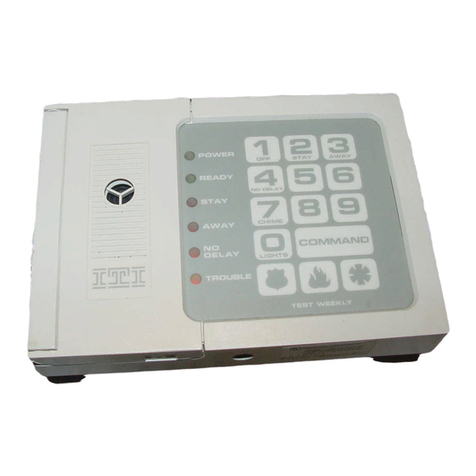
ITI ITI UltraGard User manual

Contents
This document describes the basic procedures
necessary for an experienced installer to install, set
up, and program an UltraGard™Security System.
[Check with your central station to verify they have
updated their CS-4000 with version 6.0 or later soft-
ware, for full UltraGard support.]
Installation Instructions
Document Number: 466-1034-01-ITI Rev. F
April 1997
Special Installation Requirements 1
Requirements for UL-Listed Installations 1
Canada Listings 1
California State Fire Marshall Listing 1
Installing the System 1
Determining the Panel
Location 2
Running Wires to the Panel Location 2
Mounting the Panel 2
Installing the Panel Antennas 3
Wiring the Panel 3
Setting the Optional Energy Saver Module
(ESM), Hardwire Input Module (HIM) and Hard-
wire Output Module (HOM) Unit Number DIP
Switches 4
Installing the Backup Battery 4
Powering Up the Panel 5
Adjusting Status Sound Volume 5
Programming the Panel 6
Clearing Memory 7
Entering and Exiting Program Mode 7
Deleting Sensor Text 8
Programming Sensor Text 8
Adding (Learning) Wireless Sensors 9
Adding (Learning) Hardwire Sensors 10
Deleting Sensors and Hardwire Zones 10
Programming Upper Sensors 11
Programming Optional Feature Numbers 11
Adding (Learning) Wireless Touchpads 11
Programming Panel Configuration Options 12
Programming the Primary Phone Number 12
Programming the Phone
Format 12
Programming the Siren
Time-out 13
Programming the Install Code 13
Programming the Account Number 13
Programming the Entry Delay 14
Programming the Extended Delay 14
Programming the Exit Delay 14
Programming the Activity Time-out 14
Programming the House Code 15
Programming the Energy Saver Module Freeze
and Set Temperatures 15
Programming the Touchpad Options 15
Programming the Touchpad Unit Number
16
Programming the Touchpad Quiet 16
Programming Touchpad Key Beeps 17
Programming the Interrogator 200 Audio Verifi-
cationModuleMode,Time-out,andAccessCode
17
Programming HOM Points 18
Programming the Time Zone 18
UltraGard
and Custom Versions

Contents
Viewing or Programming the User-Programma-
ble System Settings 18
The Duress Code 19
Adjusting the Alphanumeric Touchpad Display
Brightness 20
Requesting CS-4000/Downloader Program-
ming 20
Installing Line Carrier Devices 21
Installing and Programming the Wireless Interior
Siren (WIS) 21
Setting the WIS DIP Switches and Installing
the Battery 21
Connecting an External Siren to the WIS 22
Programming the WIS House Code 22
Installing X-10 Lamp Modules 22
Testing the System 23
Testing Sensors 23
If a Sensor Fails the Sensor Test 24
Testing the Energy Saver Module (ESM) 24
Testing the Hardwire Input Module (HIM) 25
Testing the Hardwire Output Module (HOM) 25
Testing the X-10 Lamp Modules 25
Testing Phone Communication 26
Testing Central Station Communication 26
Displaying the Panel
Version Code 26
Appendix A: Command Summary 27
User Operating Command Summary 27
System Settings (User-Programming) Command
Summary 28
Appendix B: Troubleshooting 29
Appendix C: Programming Tables 37
Appendix D: System Planning Worksheets 42
Appendix E: Panel Connections and Wiring 50
Appendix F: UL Requirements 53

Notices
This manual may refer to products that are announced but are not yet available.
FCC Notices
This equipment has been tested and found to comply with the limits for a class B digital device, pursuant to part 15 of the FCC rules. These limits are designed to provide
reasonable protection against harmful interference in a residential installation. This equipment generates, uses, and can radiate radio frequency energy and, if not installed and
used in accordance with the instructions, may cause harmful interference to radio communications. However, there is no guarantee that interference will not occur in a particular
installation. If this equipment does cause harmful interference to radio or television reception, which can be determined by turning the equipment off and on, the user is en-
couraged to try to correct the interference by one or more of the following measures:
• Install a quality radio or television outdoor antenna if the indoor antenna is not adequate.
• Reorient or relocate the panel.
• Move the panel away from the affected equipment.
• Move the panel away from any wire runs to the affected equipment.
• Connect the affected equipment and the panel to separate outlets, on different branch circuits.
• Consult the dealer or an experienced radio/TV technician for help.
• Send for the FCC booklet How to Identify and Resolve Radio-TV Interference Problems, available from the U.S. Government Printing Office, Washington, D.C.
20402. Stock Number: 004-000-00345-4.
This device complies with part 15 of the FCC rules. Operation is subject to the following two conditions: (1) this device may not cause harmful interference, and (2) this
device must accept any interference received, including interference that may cause undesired operation.
This equipment complies with part 68 of the FCC rules. On the FCC label affixed to this equipment is the FCC Registration Number and Ringer Equivalence Number (REN)
for this equipment. If requested, provide this information to your telephone company.
The REN is used to calculate the maximum number of devices your telephone line will support with ringing service. In most areas the sum of all device RENs should not
exceed 5.0. Contact your local telephone company to determine the maximum REN for your calling area.
If your telephone equipment causes harm to the telephone network, your telephone company may temporarily disconnect your service. If possible, you will be notified in
advance. When advance notice is not practical, you will be notified as soon as possible. You will also be advised of your right to file a complaint with the FCC.
Your telephone company may make changes in its facilities, equipment, operations, or procedures that could affect the proper operation of your equipment. You will be given
advanced notice in order to maintain uninterrupted service.
If you experience trouble with this equipment, please contact
Interactive Technologies, Inc.
2266 Second Street North
North Saint Paul, MN 55109
1-800-777-1415
for service and repair information. The telephone company may ask you to disconnect this equipment from the network until the problem has been corrected or until you are
sure that the equipment is not malfunctioning.
This equipment may not be used on coin service provided by the telephone company. Connection to party lines is subject to state tariffs.
Canada Notice
The Canadian Department of Communications label identifies certified equipment. This certification means that the equipment meets certain telecommunications network pro-
tective, operational, and safety requirements. The department does not guarantee the equipment will operate to the user’s satisfaction.
Before installing this equipment, users should ensure that it is permissible to be connected to the facilities of the local telecommunications company. The equipment must also
be installed using an acceptable method of connection. In some cases, the company’s inside wiring associated with a single-lineindividual service may be extended by means
of a certified connector assembly (telephone extension cord). The customer should be aware that compliance with the above conditions may not prevent degradation of service
in some situations.
Repairs to certified equipment should be made by an authorized Canadian maintenance facility designated by the supplier. Any repairs or alterations made by the user to this
equipment, or equipment malfunctions, may give the telecommunications company cause to request the user to disconnect the equipment.
For your protection, make sure that the electrical ground connections of the power utility, telephone lines, and internal metallic water pipe system, if present, are connected
together.
Caution
Do not attempt to make connections yourself. Contact the appropriate electrician or electric inspections authority.
The Load Number (LN) assigned to each terminal device denotes the percentage of the total load to be connected to a telephone loop that is used by the device to prevent
overloading. The termination on a loop may consist of any combination of devices subject only to the requirement that the total of the LNs of all the devices does not exceed
100. Load Number: 0.4B

“AVIS: - L ´étiquette du ministère des Communications du Canada identifie le matériel homologué. Cette étiquette certifie que le matériel est conforme a certaines normes de
protection, d ´ exploitation et de sécurité des réseaux de télécommunications. Le ministère n ´ assure toutefois pas que le matériel fonctionnera a la satisfaction de l ´ utilisateur.
Avant d ´ installer ce matériel, l ´ utilisateur doit s ´ assurer qu´ il est permis de le raccorder aux installations de l ´ enterprise locale de télécommunication. Le matériel doit
également etre installé en suivant une méthod acceptée de raccordement. Dans certains cas, les fils intérieurs de l´ enterpriseutilisés pour un service individuel a ligne unique
peuvent etre prolongés au moyen d´ un dispositif homologué de raccordement (cordon prolongateur téléphonique interne). L ´ abonné ne doit pas oublier qu ´ il est possible
que la conformité aux conditions énoncées ci-dessus n ´ empechent pas le dégradation du service dans certaines situations. Actuellement, les enterprises de télécommunication
ne permettent pas que l ´ on raccorde leur matériel a des jacks d ´ abonné, sauf dans les cas précis prévus pas les tarrifs particuliers de ces enterprises.
Les réparations de matériel homologué doivent etre effectuées pas un centre d ´ entretien canadien autorisé désigné par le fournisseur. La compagne de télécommunications
peut demander a l ´ utilisateur de débrancher un appareil a la suite de réparations ou de modifications effectuées par l ´ utilisateur ou a cause de mauvais fonctionnement.
Pour sa propre protection, l ´ utilisateur doit s ´ assurer que tous les fils de mise a la terre de la source d ´ énergie électrique, des lignes téléphoniques et des canalisations d ´´
eau métalliques, s ´ il y en a, sont raccordés ensemble. Cette précaution est particulièrement importante dans les régions rurales.
Avertissment. - L ´ utilisateur ne doit pas tenter de faire ces raccordements lui-meme; il doit avoir recours a un service d ´ inspection des installations électriques, ou
a electricien, selon le cas”.
Une note explicative sur lesindices de charge (voir 1.6) et leur emploi, a l ´ intentiondes utilisateurs du matériel terminal, doit etre incluse dans l ´ informationqui accompagne
le materiel homologué. La note pourrait etre rédigée selon le modèle suivant:
“L ´ indice de charge (IC) assigné a chaque dispositif terminal indique, pour éviter toute surcharge, le pourcentage de la charge totale qui peut etre raccordée a un circuit télé-
phonique bouclé utilisé par ce dispositif. La terminaison du circuit bouclé peut etre constituée de n ´ import somme des indices de charge de l ´ ensemble des dispositifs ne
dépasse pas 100.”
L ´ Indice de charge de cet produit est ____________.
Trademarks
ITI is a registered trademark of Interactive Technologies, Inc. UltraGard is a trademark of Interactive Technologies, Inc. X-10 is a registered trademark of X-10 (USA), Inc.

1
Special Installation
Requirements
This security system can be used as a fire warning
system, an intrusion alarm system, an emergency no-
tification system, or any combination of the three.
Some installations may require certain configurations
dictated by city codes, state codes, or insurance re-
quirements. The following information indicates the
components of various listings.
Requirements for UL-Listed
Installations
If the system is to comply with UL household require-
ments, there are specific guidelines you must follow.
Refer to appendix F for a list of compatible accesso-
ries, programming and wiring requirements in UL-
listed systems.
Canada Listings
The ULC (UL Canada) listing is pending.
CSA Certified Accessories
Residential Fire Warning System Control Unit
(ULC-S545-M89)
Basic system as described in appendix F for UL-listed
systems plus:
• Wireless Smoke Sensor (60-506), Wireless
Smoke Sensor (60-645-95), or Hardwire Smoke
Detector (13-360) (ESL 449AT) with Power
Supervision Module (60-391)
• Option F21 (Immediate Trouble Beeps) set ON
• SUPSYNC (Supervisory Synchronization) set to
2 (hours)
Note
SUPSYNC cannot be programmed from the panel. Refer to
the “Requesting CS-4000/Downloader Programming” sec-
tion for more information.
For 24-hour backup, external power drain is limited to 150
mA continuous using the heavy duty 6.5AH battery.
Residential Burglary Alarm System Unit
(ULC-S309)
Basic system as described in appendix F for UL-listed
installations plus:
• Learn Mode Door/Window Sensors (60-362)
California State Fire Marshall
Listing
The California State Fire Marshall listing is pending.
Installing the System
This section describes how to install the system con-
trol panel. Plan your system layout using the work-
sheets provided in appendix D before starting the
installation.
Installing the system consists of the following:
• Determining the Panel Location
• Running Wires to the Panel Location
• Mounting the panel
• Installing the panel antennas
• Wiring the panel
• Setting the optional Energy Saver and Hardwire
Input Module unit number dip switches
• Installing the backup battery
• Powering up the panel
• Adjusting status sound volume

Installing the System
2
Determining the Panel
Location
Before permanently mounting the panel, determine
panel location using the following guidelines:
• Centrally locate the panel with relation to wire-
less sensor locations, whenever possible.
• Avoid locations with excessive metal such as
HVAC ducts, foil wallpaper, gas/water pipes, and
electrical wiring.
• Mount the panel at a comfortable working height
(about 45 to 55 inches from the floor to the bot-
tom of the panel, as shown in figure 1).
• Allow a minimum of 10.5 inches above the panel
for the antennas, as shown in figure 1.
• Allow 6.5 inches to the right or left of the panel
for wiring, phone jack, and optional module
mounting.
• Allow at least 24 inches in front of the panel for
access to panel components.
Figure 1 Determining Panel Location
Running Wires to the Panel
Location
Once you have determined the ideal panel location,
run any necessary wires to that location, including:
• Power transformer
• Phone line
• Sirens/speakers
• SuperBus* Alphanumeric Touchpads
• Hardwire zones
• Optional SuperBus* modules (such as Energy
Saver Module [ESM], Hardwire Input Module
[HIM], Hardwire Output Module [HOM], etc.)
* SuperBus is an improved technology bus configura-
tion and is not compatible with older bus modules.
Refer to table E.3 in appendix E for wire size and type
recommendations. If you are using the same cable
type for several wireruns, use labels tomark the wires
at the panel location to help identify these wires.
Mounting the Panel
Use the procedure below to mount the panel to the
wall or wall studs, using the supplied mounting hard-
ware and the panel mounting holes shown in figure 2.
Caution
Make sure you are free of static electricity whenever you
work on the panel with the cover removed. To discharge
any static, first touch the metal panel chassis, and then stay
in contact with the chassis when touching the circuit board.
An approved grounding strap is recommended.
To mount the panel:
1. Unlock the panel cover (if cover has a key lock
installed) or remove the panel cover retaining
screws at the bottom of the panel and remove the
panel cover.
2. Swing the panel cover out and up to remove it
from the enclosure.
3. Remove the necessary wiring knockouts. Be
careful not to damage the circuit board.
4. Place the enclosure in position against the wall.
PANEL
21"
14.5"
14.5"
25"
8"
45-55"
PHONE JACK AND
OPTIONAL MODULE
MOUNTING AREA
ANTENNA
AREA
ACCESS FOR
PANEL COVER
SCREWS
NOTE
ALLOW AT LEAST 24"
IN FRONT OF PANEL
FOR ACCESS TO PANEL
COMPONENTS
FLOOR
8557G04A.DS4

Installing the System
3
Make sure enclosure is level and mark the loca-
tions of the two mounting holes and two keyhole
mounting holes. Remember to leave room for the
panel antennas, which extend 9 inches above the
top of the enclosure.
5. Use the appropriate anchors and screws. Partially
insert screws into the two anchors at the two top
keyhole locations, and then hang the panel chas-
sis on the two screws.
6. Recheck for level, insert the two lower screws,
and then tighten all four mounting screws.
Figure 2 Mounting the Panel
Installing the Panel Antennas
Caution
You must be free of static electricity before handling elec-
tronic circuit boards. Touch a grounded, bare metal surface
before handlingcircuit boards to discharge yourself of static
electricity or wear a static grounding strap.
Insert one antenna into the inside screw terminal of
each terminal block and gently tighten the screws us-
ing a small pocket-size screwdriver (figure 3).
Figure 3 Installing the Panel Antennas
Caution
Do not overtighten the terminal block screws; if youdo, per-
manent damage may result.
Wiring the Panel
Refer to appendix E for panel terminal descriptions,
wire recommendations, and typical system wiring di-
agram.
Refer to appendix F for panel programming and typi-
cal system wiring diagram for UL-listed installations.
Refer to appendix D, table D.2 to calculate the hard-
wire device power consumption for the system.
For more detailed information on installing hardwire
devices, refer to the installation instructions that ac-
company each device.
8557G08A.DS4
BACKUP
BATTERY
CONTROL
PANEL
CIRCUIT
BOARD
CONTROL
PANEL
ENCLOSURE
ANTENNAS COVER
LIP
KEYHOLE
MOUNTING
HOLES
MOUNTING
HOLES
WIRING
KNOCKOUTS
COVER
SCREWS
EARTH GROUND
CHASSIS SCREW
PANEL CIRCUIT BOARD
ANTENNA
TERMINAL
STRIPS
ENCLOSURE
ANTENNA
GROUNDING
SCREW
ANTENNA
GROUNDING
SCREW
ANTENNAS
8557G49A.DS4

Installing the System
4
Setting the Optional Energy
Saver Module (ESM), Hardwire
Input Module (HIM) and Hard-
wire Output Module (HOM)
Unit Number DIP Switches
All devices connected to the panel’s SuperBus hard-
wire bus have individual unit numbers assigned. Al-
phanumeric touchpad unit numbers are changed in
software during programming. The Energy Saver
Module (ESM), Hardware Input Module (HIM), and
Hardware Output Module (HOM) are set with DIP
switches inside the modules. For unit number setting
details, refer to the installation instructions provided
with the bus device.
Duplicated unit numbers will prevent those bus devic-
es from operating. Refer to table D.3 in appendix D
for recommended SuperBus device unit number set-
tings.
To set your ESM, HIM, or HOM unit number:
1. Set the module unit number DIP switches to the
desired unit number as shown the figure 4 per the
recommendations in table D.3 in appendix D.
The unit number is set to 0 (zero) at the factory
and is OK for most single touchpad and single
ESM, HIM, or HOM module applications. Make
sure that no bus devices (including hardwire
touchpads) share the same unit number (device
address).
Caution
Thealphanumerictouchpadunitnumberdefaultsto1(one).
Do not set the ESM, HIM, or HOM unit number to 1. Doing
so will prevent the touchpad from functioning.
2. Turn the control panel power switch off and then
back on so the bus module can read the unit num-
ber switch settings into its memory.
3. Enter and exit PROGRAM MODE by switching
the panel PROGRAM/RUN switch to PRO-
GRAM and back to RUN so the panel can
“learn” the new bus device unit numbers.
If the alphanumeric touchpad (or other SuperBus de-
vice) no longer seems to function, check if the same
unit number assigned is to more than one device. Su-
perBus devices cannot share the same unit number.
Figure 4 Setting the ESM, HIM, or HOM Unit Num-
ber Dip Switches
Note
All SuperBus devices such as Energy Saver, Hardwire In-
put,andHardwireOutputModulesand alphanumerictouch-
pads must have unique unit number (address) settings.
Deviceswith thesame(conflicting) address will notfunction
properly. Module address switches 1–5 must remain down
(off).
Installing the Backup Battery
The panel uses one rechargeable, sealed 12V lead-
acid backup battery.
Note
Both standard (60-681) 12V, 4AH and heavy duty (60-680)
12V, 6.5AH backup batteries are available. Always replace
with the same battery type and size.
8557G32A.DS4
UNIT NUMBER 0
UNIT NUMBER 1
UNIT NUMBER 2
UNIT NUMBER 3
UNIT NUMBER 4
UNIT NUMBER 5
UNIT NUMBER 6
UNIT NUMBER 7
678
12345
678
12345
678
12345
678
12345
678
12345
678
12345
678
12345
678
12345

Installing the System
5
To install (or replace) the backup battery:
1. Make sure the panel power switch is OFF and
that the transformer is unplugged from the outlet.
While AC power is applied to the panel, the
charging voltage is present at the battery leads
even with the power switch off.
2. Verify all wiring at the panel and devices for cor-
rect terminations.
3. Place the battery in the lower left or right portion
of the panel enclosure, with the terminals facing
up.
4. Connect the supplied black battery wire from the
panel circuit board negative (-) battery spade lug
(located near the power switch) to the negative (-
) battery terminal.
5. Connect the red battery wire from the panel cir-
cuit board positive (+) battery spade lug to the
positive (+) battery terminal.
WARNING!
Never short-circuit or reverse the battery wires. Possi-
ble injury to you and/or permanent damage to the panel
could result.
Powering Up the Panel
After wiring all devices to the panel and installing the
backup battery, you are ready to power up the panel.
Note
If the installation includes more than one alphanumeric
touchpad, disconnect all but one from their wiring harness-
es to reduce the possibility of a unit number (address) con-
flict. When powering up and programming are completed,
connect the remaining touchpads to their wiring harnesses.
For complete details on adding additional alphanumeric
touchpads to a working system, refer to the
SuperBus Al-
phanumeric Touchpad Installation Instructions
included
with each touchpad.
To power up the panel:
1. Plug the transformer into an outlet that is not
controlled by a switch.
2. Make sure the panel PROGRAM/RUN switch
located between the two panel terminal strips is
set to RUN (up).
3. Turn ON the panel power switch located on the
left edge of the panel and note the following:
The green power LED on the panel turns on.
Interior sirens and piezos sound one beep and in-
terior speakers announce the message Alarm sys-
tem is off.
Alphanumeric touchpad displays 1 - OFF.
Note
If the power LED is off or flashing and no beeps or voice
messages sound, turn off the panel power switch, discon-
nect the backup battery, and unplug the transformer. Refer
to appendix B, “Troubleshooting.”
4. Turn the panel power switch OFF, unplug the
transformer, and remove the existing screw
securing the AC outlet cover.
WARNING!
Use extreme caution when securing the transformer to
a metal outlet cover. You could receive a serious shock
if a metal outlet cover drops down onto the prongs of
the plug while you are securing the transformer and
cover to the outlet box.
5. Hold the outlet cover in place and plug the trans-
former into the lower receptacle.
6. Use the screw supplied with the transformer to
secure the transformer to the outlet cover.
7. Turn the panel power switch ON.
Adjusting Status Sound
Volume
The panel allows you to set the volume level for status
sounds and status messages from speakers connected
to panel terminals 8 and 9 (VOICE). Alarm sounds
and messages are preset to full volume.
To adjust the status sound volume:
1. Locate the speaker volume adjustment potenti-
ometer on the panel (above terminal 8).
Caution
Never adjust the potentiometer labeled “Do Not Adjust” lo-
cated near the power switch. Permanent damage to the
panel could result.

Programming the Panel
6
2. Press STATUS + STATUS on the alphanumeric
touchpad for a long system status display and
voice message.
Note
User-programmable system setting 77 (QuietExit) must be
off for voice sounds to be announced. (See Viewing or Pro-
gramming the User-Programmable System Settings.)
3. While listening to the message, increase the vol-
ume level by turning the volume potentiometer
clockwise.
4. Repeat steps 2 and 3 until the desired volume
level is reached.
Programming the Panel
The alphanumeric touchpad is the main programming
device for the system on-site. This touchpad is used to
enter values into panel memory, such as sensors, sen-
sor text, and system-specific configuration informa-
tion. During programming, the alphanumeric
touchpad prompts you for information in a certain or-
der. You can cycle through this order of prompts to
get to the desired programming area. For example,
you can cycle past the prompts for sensor text to enter
the system configuration information and later return
to programming sensor text.
Figure 5 shows the order of the prompts, and the area
of programming related to these prompts. Once you
know this order of prompts, you will be able to move
forward and backward in the prompt sequence to lo-
cate the programming item you need.
Examine the flowchart shown in figure 5 to familiar-
ize yourself with the sequence in which the program-
ming procedures appear. The programming software
is like a menu of choices displayed in a scroll. The di-
rection of the chart arrows represents pressing the
BYPASS button to scroll forward. To scroll back-
ward, press the STATUS button. You can also go di-
rectly to the menu choice by entering the two-digit
number shown.
When you use the alphanumeric touchpad to program
the system, the touchpad buttons have special pro-
gramming meanings and functions. Table 1 describes
the programming buttons.
Figure 5 Programming Flow Chart
AVM
TIME-OUT
AVM MODE
TOUCHPAD
OPTIONS
ACTIVITY
TIME-OUT
HOUSE
CODE
FREEZE
TEMPERATURE
SET
TEMPERATURE
EXIT DELAY
EXTENDED
DELAY
ENTRY
DELAY
ACCOUNT
NUMBER
PHONE
NUMBER
PHONE
FORMAT
SIREN
TIME-OUT
INSTALL
CODE
8557G45B.DS4
22
20
19
18
17
16
15
14
13
12
11
10
09
08
LEARN
SENSORS
DELETE
SENSORS
UPPER
SENSORS
LEARN
TOUCHPADS
07
05
04
03
F
OPTIONS
06
21
PROGRAM
MODE
DELETE
TEXT
01
PROGRAM
SENSOR
TEXT
02
AVM CODE
23
HOM
SETUP
24
25
TIME
ZONE

Programming the Panel
7
Programming the panel includes the following proce-
dures:
• Clearing memory
• Entering and exiting program mode
• Deleting and programming sensor text
• Adding and deleting wireless sensors and hardwire
zones
• Programming upper sensor numbers
• Programming optional feature numbers
• Adding wireless touchpads
• Programming panel configuration options
• Programming the phone number and format
• Programming the siren time-out
• Programming the install code
• Programming the account number
• Programming the entry, extended, and exit delays
• Programming the activity time-out
• Programming the house code
• Programming the freeze and set temperatures
• Programming the touchpad options
• Programming the Audio Verification Module
mode, time-out, and access code
• Programming HOM Setup
• Programming the Time Zone
• Viewing or programming the user-programmable
system settings
• The duress code
• Adjusting the alphanumeric touchpad display
brightness
• Requesting CS-4000/Downloader programming
Note
All on-site programming must be done using a SuperBus Al-
phanumeric Touchpad. The Alphanumeric Touchpad can
be removed once the system has been programmed.
Clearing Memory
Clear memory on all newly installed panels before
programming.
Note
Since all programming information is contained in memory,
clearing memory deletes all existing programming informa-
tion except sensor text (if any). Sensor text can be deleted
separately.
To clear panel memory:
1. Open and remove the panel door.
2. Turn the panel power switch OFF and then ON.
3. Immediately (within 1 minute after turning panel
power ON), press and hold the memory clear
button located on the upper left edge of the panel
until a relay click is heard at the panel or until
interior speakers announce Memory good-bye.
Entering and Exiting Program
Mode
The panel must be in program mode to perform any of
the on-site programming operations.
Table 1 Alphanumeric Touchpad
Programming Button Functions
Button Programming Function
Numeric
Buttons Used to enter numeric values such as
delays and sensor numbers. Also used
to enter text characters or word codes
during sensor text programming.
STATUS Scrolls backward to previous program-
ming function. Displays previous sensor
text library character during sensor text
programming. Also used to “lock in” new
alphanumeric touchpad unit numbers.
BYPASS Scrolls forward to next programming
function. Displays next sensor text
library character during sensor text pro-
gramming.
COMMAND Used to proceed or confirm displayed
entry. Displays next character/word posi-
tion in sensor text programming. Also
used to toggle between values, such as
yes/no or on/off.
FIRE Cancels and exits displayed program-
ming command (if pressed before COM-
MAND).
Backs out to previous menu level.
AUXILIARY Scrolls long display messages.
POLICE Used to clear (blank) an access code.
Used to program a pause in central sta-
tion phone number.
Used to clear HOM points.

Programming the Panel
8
To enter program mode:
1. Open and remove the panel door.
2. Set the panel PROGRAM/RUN switch to PRO-
GRAM (down).
Alphanumeric touchpads display PROGRAM MODE
and interior speakers, sirens, and piezos sound six
beeps every minute as a reminder that the panel is in
the program mode.
Note
If touchpad(s) do not display
PROGRAM MODE
after
switching the PROGRAM/RUN switch to PROGRAM
(down), a special install code has been programmed into
the panel and now must be entered into the touchpad using
the number buttons. The touchpad will display
PROGRAM
MODE
once the correct install code is entered.
The program mode of operation must be exited for the
system to operate normally (RUN). You can exit from
program mode at any time.
To exit program mode:
1. Switch the panel PROGRAM/RUN switch to
RUN (up).
2. The alphanumeric touchpad will display 1 - OFF
to signal that the system is in the normal mode of
operation.
3. When you are finished programming or working
in the control panel, replace and secure the panel
door with either the panel door screws or key
lock.
Deleting Sensor Text
You can delete all sensor text (if any)—before pro-
gramming or reprogramming, forexample—by doing
the following procedure.
To delete all existing sensor text:
1. In PROGRAM MODE, press BYPASS or STA-
TUS until DELETE TEXT is displayed.
2. Press COMMAND. Flashing RDY is displayed.
Caution
Deleted text cannot be retrieved and must be repro-
grammed.
3. Press POLICE to delete all sensor text. DELETE
TEXT DONE is displayed.
4. Press FIRE to exit.
Programming Sensor Text
This section describes how to program sensor names.
Use the word and character numbers you recorded in
appendix D (using table C.2 in appendix C) to pro-
gram sensor text.
Before programming sensor text the first time, delete
all existing text (if any) as detailed above.
To program sensor text:
1. In PROGRAM MODE, press BYPASS or STA-
TUS until the display reads PROG SENSOR
TEXT.
2. Press COMMAND and the display reads S01
[Group number assigned, if any] [“-” if nor-
mally closed, “*” if normally open] [existing
sensor text, if any].
3. Enter the desired sensor number from 01 to 76
and the display reads S## [existing sensor text, if
any].
4. Press COMMAND and the display reads A 00.
5. Enter the appropriate word number or character
number from table C.2 in appendix C.
6. Press COMMAND and the display reads B 00.
7. Repeat steps 5 and 6 until the whole sensor name
is entered.
Note
Because the touchpad can only display a limited number of
characters, in some cases—such as alarms—all text may
not be displayed.
8. Press FIRE. The display shows the sensor num-
ber and name. Lines longer than the display will
scroll horizontally. If desired, press AUXIL-
IARY to scroll the long-line display again.
9. Press BYPASS to cycle to the next sensor num-
ber and repeat steps 4 through 8 until all sensor
names are programmed.
10. Press FIRE to exit.

Programming the Panel
9
Adding (Learning) Wireless
Sensors
Programming wireless and hardwire sensors involves
switching the panel to the program mode of operation
and setting sensor identification numbers and group
numbers for each wireless sensor and hardwire sensor
loop. Once sensors IDs and group assignments are
added (learned) into panel memory, the panel can re-
spond appropriately for each sensor detection. Sen-
sors can be added (learned) into or deleted from panel
memory.
Use table C.1 in appendix C for selecting sensor
groups and complete the group assignment for each
wireless sensor in the system planning worksheets in
appendix D.
Use the following procedure to add (learn) all Learn
Mode wireless sensors.
To add Learn Mode wireless sensors into panel
memory:
1. In PROGRAM MODE, press the touchpad
BYPASS or STATUS button repeatedly until
LEARN SENSOR is displayed.
2. Press the COMMAND button to display
GROUP __ __.
3. Enter the desired group number (00 to 29, 32).
4. Press the COMMAND button to display SEN-
SOR ##.
5. Press the COMMAND button if the sensor num-
ber displayed is OK or enter another number
from 01 to 76, and then press COMMAND
again.
6. The display reads TRIP - ##. Trip the wireless
sensor tamper switch as shown in table 2 or as
described in the sensor’s installation instructions.
When the sensor has been added (learned) the
display reads TRIP - ## [next #] and interior
speakers announce Sensor # okay. Sensor [next #
to be learned].
Note
To trip a wireless sensor with an external hard-wire contact
connected to its screw terminals, check that the external
contact is in its alarm state, and then trip the sensor.
The alarm state is either open or closed, depending on the
normal condition of the sensor. Multiple normally closed
switches are wired in series and tripped while the loop is
open. Multiple normally open switches are wired in parallel
and tripped while the loop is closed.
For high-security installations, always remove both internal
reed switches when connecting an external contact to the
wireless sensor terminals.
Only the normally closed configuration can be used in UL-
listed installations.
Do not attempt to use the built-in reed switch
and
an exter-
nal contact on the same wireless sensor.
7. Continue adding sensors into the current group
number by repeating step 6 for each sensor. Press
BYPASS, STATUS, or number buttons to select
new sensor numbers (other than what is automat-
ically displayed).
8. To add sensors into other groups, press FIRE
and follow steps 3 through 7.
Table 2 Tripping Learn Mode Wireless
Sensors
Sensor * Action
Door/Window †Open sensor cover.
Fire Pull Station Open the sensor cover located
inside the Fire Pull Station.
Freeze Open sensor cover.
Glass Guard Open sensor cover.
Portable Emergency But-
tons Press the appropriate emer-
gency button(s).
PIR Motion Open PIR case.
Keychain Touchpad Simultaneously press arm and dis-
arm until the LED flashes.
Rate-of-Rise Heat Open sensor cover and press learn
switch on circuit board.
Recessed Door/Window Open sensor cover and remove
transmitter circuit board.
Shock †Open sensor cover.
Slim Line Door/Window Remove sensor from mounting
base.
Sound Open sound sensor cover, after
spring is installed.
System Sensor Smoke
System Sensor 2300RF ITI
Press test button and hold for
30 seconds, until test alarm
begins sounding.
With sensor removed from base,
press the test button for at least
1 second.
*Refer to the particular sensor’s installation instructions for
more details on tripping Learn Mode wireless sensors.
†When using an external contact with this sensor, the contact
must be in the alarm state while tripping the sensor to properly
learn it into memory.

Programming the Panel
10
9. Press FIRE to exit. Proceed to your next pro-
gramming task.
10. If you are finished programming, switch the
panel PROGRAM/RUN switch to RUN (up).
The touchpad will display 1 - OFF to signal that
the system is in the normal (RUN) mode of oper-
ation.
Adding (Learning) Hardwire
Sensors
After planning the installation, use table C.1 in appen-
dix C to select sensor groups and complete the group
assignment for each wireless sensor in the system
planning worksheets in appendix D.
Use the following procedure to add (learn) all hard-
wire sensors and zones into panel memory.
To add (learn) hardwire sensors:
1. Place all hardwire sensors in their normal (non-
alarm) state.
2. In PROGRAM MODE, press the touchpad
BYPASS or STATUS button repeatedly until
LEARN SENSOR is displayed.
3. Press the COMMAND button to display
GROUP __ __.
4. Enter the desired group number (00 to 29, 32).
5. Press the COMMAND button to display SEN-
SOR ##.
6. Press the COMMAND button if the sensor num-
ber displayed is correct or enter another number
from 01 to 76, and then press COMMAND
again.
7. The display reads TRIP - ##. Trip the sensor by
placing it into the alarm state (open the door or
window) or as described in the sensor’s installa-
tion instructions. The display reads TRIP - ##
[next #] and interior speakers announce Sensor #
okay. Sensor [next # to be learned].
Note
The alarm state is either open or closed, depending on the
normal condition of the sensor. Multiple normally closed
switches are wired in series and tripped while the loop is
open. Multiple normally open switches are wired in parallel
and tripped while the loop is closed.
On hardwire zones containing multiple sensors, only one
sensor per zone needs to be added (learned) into panel
memory.
If the system uses hardwire sensors only, turn off upper
sensor 94 (Receiver Failure) in the panel.
Only the normally closed configuration can be used in UL-
listed installations.
8. Continue adding sensors into the current group
number by repeating step 7. Press BYPASS,
STATUS, or number buttons to select new sen-
sor numbers.
9. To add sensors into other groups, press FIRE
and follow steps 4 through 8.
10. Press FIRE to exit. Proceed to your next pro-
gramming task.
11. If you are finished programming, switch the
panel PROGRAM/RUN switch to RUN (up).
The touchpad will display 1 - OFF to signal that
the system is in the normal (RUN) mode of oper-
ation.
Deleting Sensors and Hard-
wire Zones
If you want to reassign a sensor or hardwire zone to
another group, you must first delete that sensor or
zone.
To delete a sensor from the panel:
1. In PROGRAM MODE, press STATUS or
BYPASS until the display reads DELETE SEN-
SOR.
2. Press COMMAND and the display reads
DELETE ## [sensor text, if any].
Note
After pressing COMMAND in step 2, the display shows the
lowest programmed sensor number.
3. If the sensor number displayed is not correct,
enter the desired number (01 to 76).
4. Press COMMAND and the display reads DEL
## OK.
5. Continue deleting sensors by repeating steps 3
and 4.

Programming the Panel
11
6. Press FIRE to exit.
Note
Sensor text is not deleted when its sensor is deleted.
Programming Upper Sensors
Upper sensors are optional values (see appendix D,
table D.7) you turn on or off depending on your cus-
tomer’s equipment and needs.
Note
We recommend that you do not change upper sensors that
default ON. Factory default settings will work for most appli-
cations.
Use the settings recorded in appendix D, table D.7
when programming upper sensors.
To program upper sensor numbers:
1. In PROGRAM MODE, press BYPASS or STA-
TUS until UPPER SENSOR is displayed.
2. Press COMMAND and the display reads 77 -
OFF TOUCHPAD TAMPER. (Press AUXIL-
IARY to scroll any long messages sideways.)
3. Press COMMAND to toggle upper sensor 77
ON, if desired, or press BYPASS to cycle to the
next upper sensor.
Note
To jump directly to a particular upper sensor, enter its two-
digit number instead of pressing BYPASS.
4. Repeat step 3 until all upper sensors are pro-
grammed to suit the installation.
5. Press FIRE to exit.
Programming Optional
Feature Numbers
Optional feature numbers are system features (see ap-
pendix D, table D.8) you turn on or off depending on
your customer’s needs.
Note
We recommend that you do not change feature numbers
that default ON. Factory default settings will work for most
applications.
Use the settings recorded in table D.8 when program-
ming optional feature numbers.
To program feature numbers:
1. In PROGRAM MODE, press BYPASS or STA-
TUS until F OPTIONS is displayed.
2. Press COMMAND to display 00 - ON REMOTE
ACCESS. (Press AUXILIARY to scroll long
messages in the display.)
3. Press COMMAND again to toggle the feature
number ON or OFF as desired.
4. Press BYPASS to display the next feature num-
ber.
Note
To jump directly to a particular feature number, enter its
number instead of pressing BYPASS.
5. Repeat steps 3 and 4 for all of the remaining fea-
ture numbers.
6. Press FIRE to exit.
Adding (Learning) Wireless
Touchpads
You can add up to four wireless touchpads to the sys-
tem (including keychain touchpads).
To add (learn) wireless touchpads:
1. In PROGRAM MODE, press BYPASS or STA-
TUS until LEARN TOUCHPAD is displayed.
2. Press COMMAND to display PRESS BYP TP -
1.
3. Press BYPASS on the wireless touchpad (press
and hold both lock and unlock buttons on the
wireless keychain touchpad) until the display
reads PRESS BYP TP 2 and One OK, Two is
heard.
4. Repeat step 3 for each wireless touchpad until
they are all added.
5. Press FIRE to exit.

Programming the Panel
12
Caution
After exiting from learning touchpads, reentering the learn
touchpads menu by pressing COMMAND automatically de-
letes all learned touchpads. When adding wireless touch-
pads to the system, you must also relearn existing
touchpads.
Programming Panel
Configuration Options
This section describes how to program the following:
• Primary phone number and phone format
• Siren time-out
• Install code
• Account number
• Entry, extended, and exit delays
• Activity time-out
• House code
• Energy Saver Module (ESM) freeze and set tem-
peratures
• Touchpad unit number, quiet, and key beeps
options
• Audio Verification Module (AVM) mode, time-
out, and code
• HOM setup
• Time zone
• User-programming system settings
• Duress code
Use the panel configuration settings you recorded in
table D.5 to program the system.
Programming the Primary
Phone Number
The panel can report alarms and all other reports to a
central monitoring station by programming the prima-
ry phone number (or central station’s phone number)
into panel memory. The default phone number is
blank (none).
To program the central monitoring station tele-
phone number:
1. In PROGRAM MODE, press BYPASS until the
display reads PHONE NUMBER.
2. Press COMMAND. The display shows [existing
phone number, if any].
3. Enter the central station receiver phone number
(up to 18 digits). If you need a pause between
digits, press POLICE for each 1-second pause
desired.
4. Press COMMAND. The display reads [new
phone number].
5. Press FIRE to exit.
Programming the Phone
Format
The phone format determines the type of communica-
tion the panel uses to report to the central monitoring
station’s receiver. The default phone format is “ITI.”
To program the panel telephone format:
1. In PROGRAM MODE, press BYPASS until the
display reads PHONE FORMAT.
2. Press COMMAND to display the currently
selected format. For example, ITI FMT.
3. Press BYPASS or STATUS to cycle to the
desired setting: SET ITI, -1400, or -2300.
Note
Phone format must be set to “ITI” for the panel to correctly
communicate with the ITI ToolBox Downloader.
4. Press COMMAND and the display reads SET
[selected format] OK.
5. Press FIRE to exit.

Programming the Panel
13
Programming the Siren
Time-out
The siren time-out determines how long sirens sound
an alarm condition, if no one is present to disarm the
system. The default siren time-out is 4 minutes.
To program a different siren time-out:
1. In PROGRAM MODE, press BYPASS until the
display reads SIREN TIMEOUT.
2. Press COMMAND and the display reads SIREN
- ## MIN.
3. Enter the desired two-digit time (01 to 30 min-
utes).
4. Press COMMAND and the display reads SIREN
- ## MIN.
5. Press FIRE to exit.
Programming the Install Code
The install code is a special access code used to pre-
vent accidental or unauthorized changes to system
programming. The default install code is blank
(****).
Caution
Always install and test all wired touchpads before entering
an install code. Programming an install code before all
touchpads are installed and tested is risky. It can lead to a
situation where memory must be cleared to get into pro-
grammode. Thiscan happenif a bus conflict renders the al-
phanumeric touchpad useless (and there are no wireless
touchpads and phonecontrol is turned off). Inthis situation,
there is no way to enter an install code—there is no way to
get back into the program mode except to erase the install
code (and all other programming) by clearing memory.
If an install code is desired, program it after installation is
complete and just before you leave the site.
Note
Once an install code is entered, it will start a 1-hour timer.
For the next hour, the install code will not be required. This
timer is cleared by entering dealer sensor test.
To program an install code:
1. In PROGRAM MODE, press BYPASS until the
display reads INSTALL CODE.
2. Press COMMAND to display INSTALL - ****.
3. Enter any four digits from 0001 to 9998.
Note
See table D.6 in appendix D for code number defaults and
restrictions.
To return the install code to blank (****) press the POLICE
button instead of a four-digit code.
4. Press COMMAND. INSTALL - #### is dis-
played.
5. Press FIRE to exit.
Programming the Account
Number
The account number is a five-character panel identifi-
cation for central monitoring stations. Used when the
panel sends reports. The default account number is
00-000.
To program an account number:
1. In PROGRAM MODE, press BYPASS until the
display reads ACCOUNT NUMBER.
2. Press COMMAND to display ACCOUNT -
#####.
3. Enter any five digits.
4. Press COMMAND. ACCOUNT - ##### is dis-
played.
5. Press FIRE to exit.
Note
Onlynumberscanbeprogrammedlocallythoughthe alpha-
numeric touchpad. Letters can be programmed though the
CS-4000 or Downloader and will display correctly with the
panel in program mode.

Programming the Panel
14
Programming the Entry Delay
The entry delay determines the time a user has toenter
the premises and disarm the system, before it goes
into alarm. The default entry delay is 32 seconds.
To program a different entry delay:
1. In PROGRAM MODE, press BYPASS until the
display reads ENTRY DELAY.
2. Press COMMANDand the display readsENTRY
- ### SEC.
3. Enter the desired three-digit time (008 to 120
seconds).
Note
Thesystemautomaticallyroundsofftheentrytothenearest
multiple of eight.
4. Press COMMANDand the display readsENTRY
- ### SEC.
5. Press FIRE to exit.
Programming the Extended
Delay
The extended delay affects both entry and exit delay
times for sensors in groups 11 (extended delay) and
12 (twice extended delay). The extended delay setting
determines how much time system users have to leave
the premises after arming and how much time users
have to disarm after entering, without causing an ac-
cidental alarm. The default extended delay is 4 min-
utes.
To program a different extended delay:
1. In PROGRAM MODE, press BYPASS until the
display reads EXTENDED DELAY.
2. Press COMMAND. The display reads DELAY -
## MIN.
3. Enter the desired two-digit time (01 to 08 min-
utes).
4. Press COMMAND and the display reads
DELAY - ## MIN.
5. Press FIRE to exit.
Programming the Exit Delay
The exit delay determines how much time system us-
ers have to leave the premises through a designated
delay door without causing an alarm, after arming the
system. The default exit delay is 32 seconds.
To program the exit delay:
1. In PROGRAM MODE, press BYPASS until the
display reads EXIT DELAY.
2. Press COMMAND and the display reads EXIT -
### SEC.
3. Enter the desired three-digit time (008 to 184
seconds).
Note
The system automatically rounds off the entry to the nearest
multiple of eight.
4. Press COMMAND and the display reads EXIT -
### SEC.
5. Press FIRE to exit.
Programming the Activity
Time-out
The activity time-out determines how many hours of
system non-use are sensed, before sending a report to
the central monitoring station. The default activity
time-out is 24 hours.
To program a different activity time-out:
1. In PROGRAM MODE, press BYPASS until the
display reads ACTIVITY TIMEOUT.
2. Press COMMAND to display ACTIVITY - ## H.
3. Enter the desired two-digit time (01 to 24 hours).
4. Press COMMAND. ACTIVITY - ## H is dis-
played.
5. Press FIRE to exit.
Note
Upper sensor S79 (No Activity) must be on for the activity
timer to function. S79 default is off.

Programming the Panel
15
Programming the House Code
The house code is a three digit number used to com-
municate panel signals to line carrier devices such as
Wireless Interior Sirens (WIS) and X-10 Lamp and
Appliance Modules. The default house code is 001(X-
10 module house code “B”).
To program a different house code:
1. In PROGRAM MODE, press BYPASS until the
display reads HOUSE CODE.
2. Press COMMAND to display HOUSE CODE -
### [X-10 module unit code A–P].
3. Enter the desired three digit house code number
(001 to 254).
4. Press COMMAND. HOUSE CODE - ### [X-10
module unit code A–P] is displayed.
5. Press FIRE to exit.
Programming the Energy
Saver Module Freeze and Set
Temperatures
The freeze temperature setting determines when the
Energy Saver Module’s freeze sensor activates,
sounding interior sirens and reporting to the central
monitoring station. The default freeze temperature is
42° F.
Note
Uppersensor78(FreezeSensor)mustbeON toenablethe
freeze alarm. Upper sensor 78 defaults to OFF.
To program the Energy Saver Module freeze tem-
perature:
1. In PROGRAM MODE, press BYPASS until the
display reads FREEZE TEMP.
2. Press COMMAND and the display reads
FREEZE TEMP - ##.
3. Enter the desired two-digit temperature (40 to
90).
4. Press COMMAND and the display reads
FREEZE TEMP - ##.
5. Press FIRE to exit.
The Energy Saver Module set (readout) temperature
setting lets you adjust the module to match the on-pre-
mises thermostat. The default set temperature is the
unadjusted ESM temperature.
To adjust the Energy Saver Module temperature
readout, make sure that the module is wired and
working, then:
1. In PROGRAM MODE, press BYPASS until the
display reads SET TEMP.
2. Press COMMAND to display TEMPERATURE
- ##.
3. Enter present two-digit room temperature (32 to
99).
4. Press COMMAND and the display reads TEM-
PERATURE - ##.
5. Press FIRE to exit.
Programming the Touchpad
Options
The touchpad options setting lets you set the touchpad
unit number, touchpad quiet, and touchpad key beeps
options.
To program the alphanumeric touchpad options:
1. In PROGRAM MODE, press BYPASS until
TOUCHPAD OPTIONS is displayed.
2. Press COMMAND to display UNIT NUMBER.
3. Press BYPASS to display the various touchpad
options.
4. Continue with the following touchpad option
procedures.

Programming the Panel
16
Programming the Touchpad
Unit Number
The touchpad unit number lets the panel identify spe-
cific touchpads connected to the bus. Each alphanu-
meric touchpad must be assigned a unit number,
different than any other bus device. Use the following
guidelines when changing touchpad unit numbers:
• Always start with one touchpad connected to the
panel and get it operational with the panel, before
connecting additional touchpads.
• Whenever possible, such as in new installations,
assign alphanumeric touchpad unit numbers
before all other panel programming.
• Always work from one touchpad location when
assigning unit numbers for installations with
multiple touchpads.
For complete details on installing additional alphanu-
meric touchpads to a working system, refer to the Su-
perBus Alphanumeric Touchpad Installation
Instructions included with each touchpad.
The default touchpad unit number is 001.
Note
On systems with multiple alphanumeric touchpads, the fol-
lowing procedure puts all touchpads into the address set
mode.
Caution
Always delete (blank) the install code before adding wired
touchpads or changing wired touchpad unit (address) num-
bers. The default install code is blank (****).
Programming an install code before all touchpads are in-
stalled and tested may prevent correct touchpad installation
andmay requireclearingmemoryand reprogramming.Ifan
install code is desired, program it after installation is com-
plete and just before you leave the site.
To delete (blank) theinstall code prior to changing
the touchpad unit number:
1. In PROGRAM MODE, press BYPASS until the
display reads INSTALL CODE.
2. Press COMMAND to display INSTALL - ####.
3. Press the POLICE button. INSTALL - ****
(blank) is displayed.
4. Press FIRE to exit.
To change the alphanumeric touchpad unit num-
ber:
1. In PROGRAM MODE, press BYPASS until
TOUCHPAD OPTIONS is displayed.
2. Press COMMAND. Display reads UNIT NUM-
BER.
3. Press COMMAND to display the present unit
number DA ###.
4. Press COMMAND to display ENTER _.
5. Enter the desired three digit touchpad unit num-
ber (000 to 007).
6. Press STATUS to lock in the new unit number.
Note
The touchpad will be nonfunctional after its unit number is
changed until it is reactivated as follows.
7. Switch the panel PROGRAM/RUN switch to
RUN (up) and back to PROGRAM (down) to
reactivate the touchpad with its new unit number.
Touchpad will display PROGRAM MODE.
Programming the Touchpad
Quiet
The touchpad quiet option determines whether status
sounds are heard from a specific touchpad. If there is
more than one touchpad, the following procedure
must be done at each touchpad you want changed.
The touchpad quiet default is N (no—not quiet).
To changed the alphanumeric touchpad quiet op-
tion:
1. In PROGRAM MODE, press BYPASS until
TOUCHPAD OPTIONS is displayed.
2. Press COMMAND. Display reads UNIT NUM-
BER.
3. Press BYPASS or STATUS until the display
reads TOUCHPAD QUIET N (no) or Y(yes).
4. Press COMMAND to toggle from Yor N.
5. Press FIRE to exit.
Other manuals for ITI UltraGard
1
Table of contents
Other ITI Security System manuals

ITI
ITI CareTaker Plus User manual

ITI
ITI Concord Express User manual

ITI
ITI Commander 2000 User manual

ITI
ITI Caretaker User manual

ITI
ITI PinPoint System 128 User manual

ITI
ITI Commander III Instruction sheet

ITI
ITI WIS User manual

ITI
ITI RF commander User manual

ITI
ITI Commander IIII User manual

ITI
ITI Caretaker User manual
Popular Security System manuals by other brands

Esse-ti
Esse-ti HELPY COMPACT-Q quick guide

Federal Signal Corporation
Federal Signal Corporation PA4000 Installation, operation and service instructions

SkyLink
SkyLink SC-100 Guide manual

GE
GE TX-7201-05-1 quick start guide

3M
3M Cavius 9003-002 quick start guide

ICP DAS USA
ICP DAS USA ALM-Horn Series user manual