ITOH DENKI POWER MOLLER HBL-606FN Technical manual

Specifications subject to change without notice
ITOH DENKI USA, INC
135 Stewart Road rev15-0615
PH: 570-820-8811 Hanover Industrial Estates
FX: 570-820-8838 Wilkes-Barre, PA 18706-1462 Page 1 of 26
HBL-606FN/FP Technical Document
General Features
•Operates LE and LD series motors
•Runs one or two Power Mollers in one or two zone configurations
o3 pin motor connector only
•LED indications for operation and error statuses
•Automatic or manual recovery for error statuses
•Motor protection against overheating, stall condition and overspeeding
•Lead free design for RoHS conformity
•Logic for general zero pressure accumulation (ZPA) is built-in
oSingulated release
oSlug (train) release with Flexible Zone Recognition (patented)
•Direct connection for two photo-sensors for power and signal
•Easy connection between adjacent HBL-606F’s with communication cables simplifies wiring
•Independent speed control for each motor
•Adjustable timers by rotary switch
•Automatically detects the end of a conveyor line for accumulation when the communication cable is disconnected
•Stable speed function to ensure that different weight articles travel at the same rate
•Enclosure is made from fire resistant ABS

Specifications subject to change without notice
ITOH DENKI USA, INC
135 Stewart Road rev15-0615
PH: 570-820-8811 Hanover Industrial Estates
FX: 570-820-8838 Wilkes-Barre, PA 18706-1462 Page 2 of 26
Table of Contents
Subject
Page
Features
1
General Features
1
Table of Contents
2
General Information
3
Dimensions
3
User Interface
3
Standard Conveyor Configuration
3
Connections
4
Installation Precautions
Please read before installation
8
Switch Settings
10
Input / Output Settings
10
Speed Settings
13
Timer
Settings
1
4
Other Settings
15
PNP / NPN Settings
15
LED and Error
Indications
1
6
Conveyor Zone
Configuration 20
Standard Zone
20
Infeed Zone
21
Discharge Zone
22
Single Zone One MDR
23
Single Zone Two MDR
24
Handshake signals HBL to IB-E
25
Revision History
26

Specifications subject to change without notice
ITOH DENKI USA, INC
135 Stewart Road rev15-0615
PH: 570-820-8811 Hanover Industrial Estates
FX: 570-820-8838 Wilkes-Barre, PA 18706-1462 Page 3 of 26
General Information
Dimensions
CN302
CN301
CN1
CN101 CN402
CN201
CN4
CN401
SW1 SW2
SW3 SW4SW5
0V
SEN
24V
Sensor A
Port
Power
A
MOTOR A
Port
B
24V
SEN
0V
Sensor B
1 DIR/RST
2 AUTO/MANU
3 NPN/PNP OUT
4 ZP1/ZP2
5 DIRCTION A
DIRCTION B
7 ZONE 2/1
8 ERR ON/PLS
1 SEN/SYN A
2 SEN/SYN B
3 STOP/RUN A
4 STOP/RUN B
MOTOR B
PWR
I/O
CTRL
SEN A
SEN B
0V
24V
58mm
[2.28"]
29mm
[1.13"]
210mm
[8.27"]
220mm
[8.66"] 32mm
[1.24"]
User Interface – Default Settings
1 SEN/SYN A
2 SEN/SYN B
3 STOP/RUN A
4 STOP/RUN B
CTRL
SEN A
SEN B
1 DIR/RST
2 AUTO/MANU
3 NPN/PNP OUT
4 ZP1/ZP2
5 DIRCTION A
6 DIRCTION B
7 ZONE 2/1
8 ERR ON/PLS

Specifications subject to change without notice
ITOH DENKI USA, INC
135 Stewart Road rev15-0615
PH: 570-820-8811 Hanover Industrial Estates
FX: 570-820-8838 Wilkes-Barre, PA 18706-1462 Page 4 of 26
Connections
CN1
2 PIN connector for Power
Female Connector for Wiring
WAGO #231-302 / 026-000
PIN Description
1 +24V DC ±10% (full-wave rectified, smoothed current <10% ripple) Wire size
28~14AWG
2 0V
CN
4
(Ordered Separately)
6 PIN connector for External Control
Female Connector for Wiring
WAGO #733-106
PIN Description
1 Direction or error reset (selectable on SW1-1)
Wire size:
28~20AWG
2 Motor A forcible run or stop (selectable on SW2-3)
3 Motor B forcible run or stop (selectable on SW2-4)
4 Error output
5 Motor A synchronization or sensor output (selectable on SW2-1)
6 Motor B synchronization or sensor output (selectable on SW2-2)
C
N3
01, CN401
3 PIN connector for Photo Sensor
Female Connector for Wiring
WAGO #733-103
PIN Description
1 +24V DC Wire size:
28~20AWG
2 +24V or 0V DC input (sensor signal input)
3 0V
0V
SEN
24V
Sensor A
Port
Power
A
MOTOR A
Port
B
24V
SEN
0V
Sensor B
1 DIR/RST
2 AUTO/MANU
3 NPN/PNP OUT
4 ZP1/ZP2
5 DIRCTION A
6 DIRCTION B
7 ZONE 2/1
8 ERR ON/PLS
1 SEN/SYN A
2 SEN/SYN B
3 STOP/RUN A
4 STOP/RUN B
MOTOR B
PWR
I/O
CTRL
SEN A
SEN B
0V
24V
0V +24VDC
PSOutput
CN401
CN1 CN301
+24VDC
0V
0V
+24VDC PSOutput
Connection Instructions for CN1, CN4, CN301 & CN401
Press down spring clamp in connector with a small screwdriver.
Insert leads in proper order.
(Lead should be stripped approx: 0.31~0.35”)
WAGO connector must be inserted and/or pulled out carefully, so as not to damage
other parts.

Specifications subject to change without notice
ITOH DENKI USA, INC
135 Stewart Road rev15-0615
PH: 570-820-8811 Hanover Industrial Estates
FX: 570-820-8838 Wilkes-Barre, PA 18706-1462 Page 5 of 26
Connections
(continued)
Input / Output settings CN4
CN4-1 – Direction / Error reset (selectable by SW1-1; see page 11)
•Direction input (SW1-1; OFF) [Default]
oReverses the logic flow and motor direction while the input is active. Logic flow is independent of motor
direction.
oThis signal is shared through the communication cable.
•Error reset input (SW1-1; ON)
oResets error conditions at the time the signal is input only when the card is in operational condition and
causes of errors have been removed. This signal is shared through the communication cable.
o
CN4-2 – Input A (selectable by SW2-3; see page 12)
•Forcible run motor A input (SW2-3; ON) [Default]
oForcibly runs motor A while signal is active
•Forcible stop motor A input (SW2-3; OFF)
oForcibly stops motor A when sensor A becomes blocked while signal is active
CN4-3 – Input B (selectable by SW2-4; see page 12)
•Forcible run motor B input (SW2-3; ON) [Default]
oForcibly runs motor B while signal is active
•Forcible stop motor B input (SW2-3; OFF)
oForcibly stops motor B when sensor B becomes blocked while signal is active
CN4-4 – Error output (selectable by SW1-8; see page 11) [25mA maximum]
•Pulsed output (PLS; ON)
oUsed when connecting the error output to an IB-E03 / 04 remote input 1 (CN301-1 on IB-E series)
PNP pulse with SW2-3 ON
NPN pulse with SW2-3 OFF
•Output signal (ERR ON; OFF) [Default]
oOutputs a signal when an error occurs
PNP signal with SW2-3 ON
NPN signal with SW2-3 OFF
CN4-5 – Output A (selectable by SW2-1; see page 12) [25mA maximum]
•Synchronous output (SYN A; SW2-1 ON) [Default]
oOutputs a signal on CN4-5 when motor A runs
•Sensor output (SEN A; SW2-1 OFF)
oOutputs a signal on CN4-5 when sensor A is blocked
CN4-6 – Output B (selectable by SW2-2; see page 12) [25mA maximum]
•Synchronous output (SYN B; SW2-1 ON) [Default]
oOutputs a signal on CN4-6 when motor B runs
•Sensor output (SEN B; SW2-1 OFF)
oOutputs a signal on CN4-6 when sensor B is blocked

Specifications subject to change without notice
ITOH DENKI USA, INC
135 Stewart Road rev15-0615
PH: 570-820-8811 Hanover Industrial Estates
FX: 570-820-8838 Wilkes-Barre, PA 18706-1462 Page 6 of 26
Connections
(continued)
CN
302
& CN
402
8 PIN connector for Communication Cable
Fem
ale Connector for Wiring
RJ-45
CN302 & CN402 Description
1 Error status
Wire size:
26AWG
or
Equivalent 8 wire
cable
2 Error status
3 Motor status
4 Motor status
5 Error reset
6 0V DC
7 Sensor status
8 Sensor status
Communication Cable – Straight-through wiring (Not crossover)
180°
8754321
1
1

Specifications subject to change without notice
ITOH DENKI USA, INC
135 Stewart Road rev15-0615
PH: 570-820-8811 Hanover Industrial Estates
FX: 570-820-8838 Wilkes-Barre, PA 18706-1462 Page 7 of 26
Connections
(continued)
CN
101, CN201
3 PIN connector for Motor
Male Connector on Card
JST #S3B-XH-A
Female Connector for Wiring
JST #XHP-3
PIN Description
1 Motor phase U – Red Wire size:
24~22AWG
Terminal pins:
JST #SXH-001T-P0.6
2 Motor phase V – White
3 Motor phase W – Black
1
PIN 1 indicator
1

Specifications subject to change without notice
ITOH DENKI USA, INC
135 Stewart Road rev15-0615
PH: 570-820-8811 Hanover Industrial Estates
FX: 570-820-8838 Wilkes-Barre, PA 18706-1462 Page 8 of 26
Installation Precautions –
IMPORTANT, PLEASE READ BEFORE INSTALLATION
Precaution
Action
Reason
Sensor
Use a sensor that would have an active
output when the zone is occupied
Example: A retro-reflective photo-
sensor would need to be dark-operate
The HBL responds to the active signal
received from the sensor to denote zone
occupation. If the incorrect type is used, the
HBL would “think” that a zone is occupied
when it is really clear. Not only would there
be problems in ZPA logic operation, but there
will also be JAM errors appearing.
Powering ON
Keep away from the system when it is
first powered ON. When the system is first powered ON and
there is no signal from the photo-sensor for
presence of an article, the zone will RUN for
a short time at a slow speed to receive or
advance any articles which may be between
photo-sensors. There may be a risk for
bodily injury because of moving rollers and
transported articles.
Using as a slave card be sure the timer
switch SW5 to zero (0) for slave mode This eliminates all timer functions and
communication. Roller(s) will not run on
initial start up in slave mode
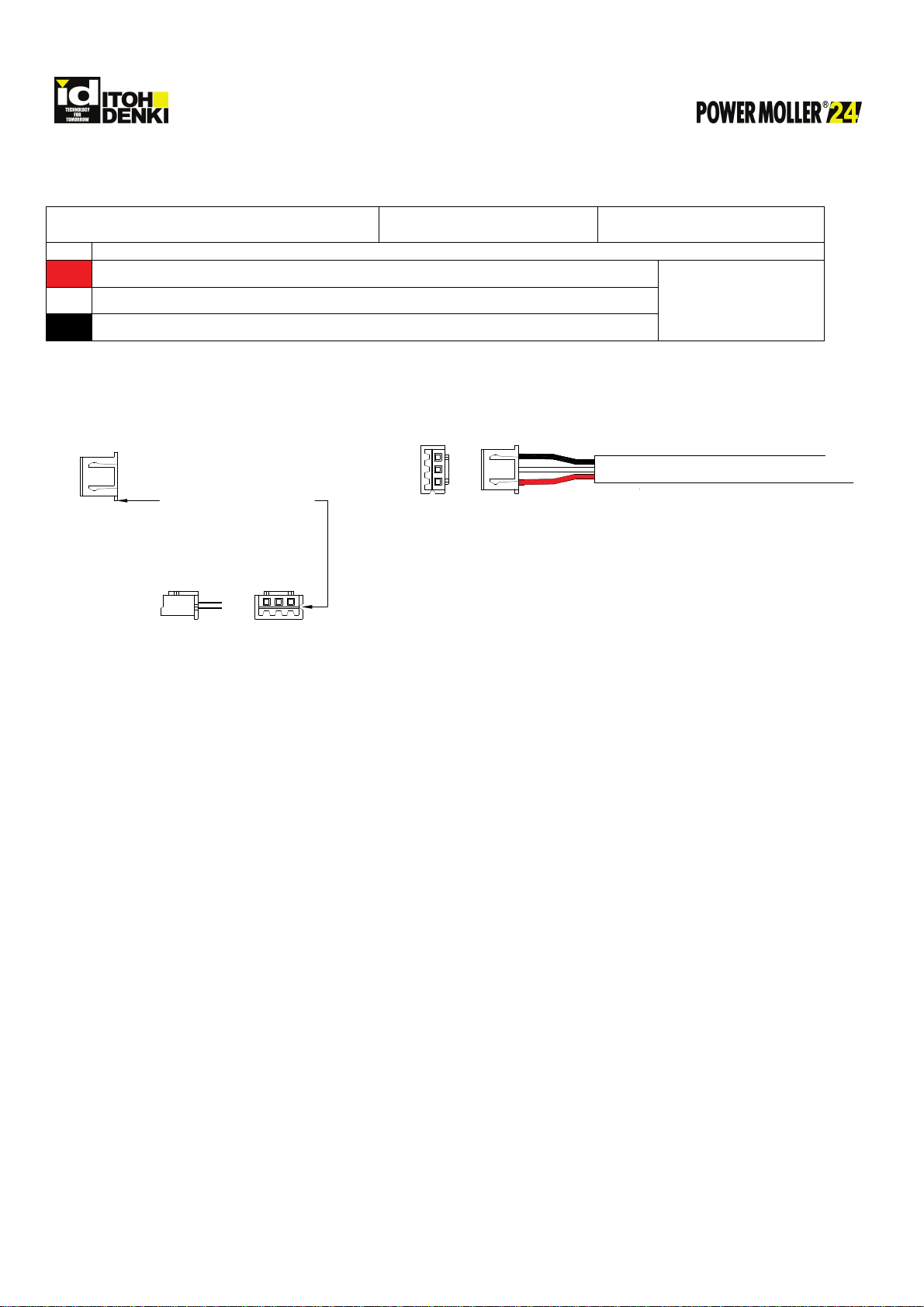
Correct c
ables
RJ-45 connectors
8-wire cables
Straight-through wiring pattern
Straight-through wiring means that the
connectors on both ends of the cable are
wired in the exact same pattern.
Cross-over wiring or any other wiring pattern
will cause communication problems.
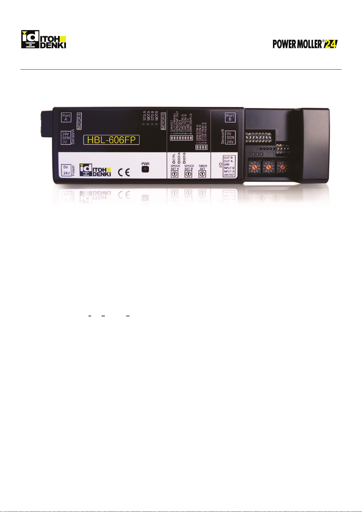
Low impedance
connection to PNP
output(s)
DO NOT connect an output terminal
(CN2-4, CN2-5) set for PNP directly to
0V, GND, or a low impedance input on a
controller.
When the PNP signal is active, the low
impedance input will draw a high current and
subsequently damage the output circuit.
Damage may also occur to the input circuit
on the controller. 25mA maximum
Multiple power
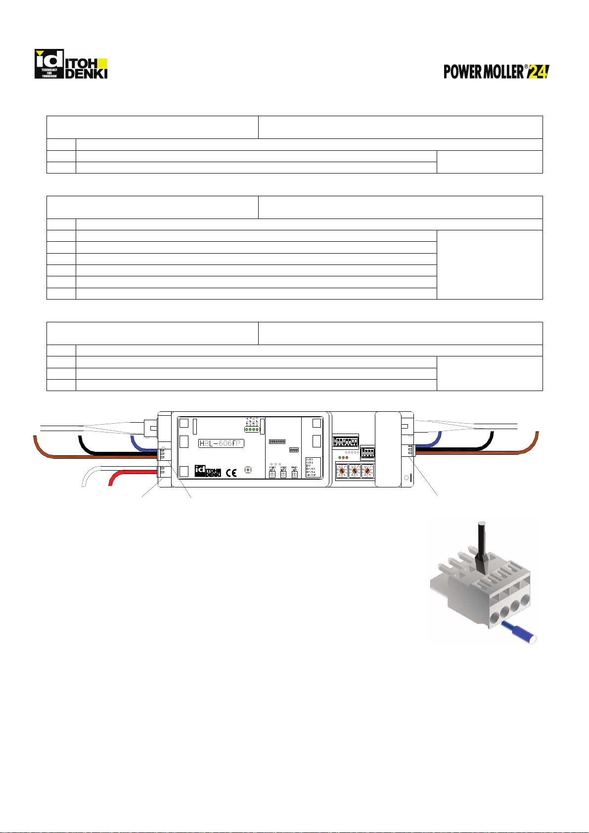
supplies 0V line of all power supplies on the
same conveyor line (powering the
card/rollers, & controls) need to be
physically linked together.
This completes the signal path from one
section of the conveyor (powered by a power
supply) to the adjacent section of conveyor
(powered by another power supply) and
allows for proper communication through the
cable and external interfaces.

Specifications subject to change without notice
ITOH DENKI USA, INC
135 Stewart Road rev15-0615
PH: 570-820-8811 Hanover Industrial Estates
FX: 570-820-8838 Wilkes-Barre, PA 18706-1462 Page 9 of 26
Installation Precautions
(continued)
Precaution
Action
Reason
Voltage drop
across
the power bus Use suitable gauge wire in relation to
distance and current draw to prevent
voltage drop.
Operating DC voltage is 24V ±10%
When running long distances from a DC
power supply, the voltage drop during motor
operation across the power bus may be
significant (may drop below 15V!). If there is
a large enough drop in voltage, the roller(s)
may behave in a strange manner. In order to
prevent this, a larger gauge wire must be
used.
Grounding
The conveyor frame should be at the
same potential reference as earth
ground. Standard grounding practices
should be followed.
Static discharge may interfere with general
logic processing, and in possibly damage IC
components on the circuit board.
Environment
Ambient temperature is 32~104°F
Ambient humidity is < 90%RH
Atmosphere has no corrosive gas
Vibration is < 0.5G
Indoor use only
Extreme environmental variables may cause
poor or no performance and damage the
card.
Over
-
speeding
Over-speeding of the roller’s no-load
speed by more than 50% may cause
damage.
Back EMF will be generated.
Electrical
24V DC ±10%
2A maximum current limiter
(motor lock is 2A)
Diode protection for miss-wiring
Sensor power short circuit protection
5A fuse per motor driver for power
supply protection
Improper power will damage the card.
The motor/card should not be subject to
locked conditions repeatedly.
Internal fuse is not replaceable. If the fuse
has blown, more serious damage has
occurred within the card/motor.

Specifications subject to change without notice
ITOH DENKI USA, INC
135 Stewart Road rev15-0615
PH: 570-820-8811 Hanover Industrial Estates
FX: 570-820-8838 Wilkes-Barre, PA 18706-1462 Page 10 of 26
Switch Settings
Input / Output Settings SW1
DIP
Switch Function ON OFF
Default
Setting
1
-
1
Error Reset or Direction input Error reset Direction
OFF
1
-
2
Error recovery
Manual
Automatic
ON
1-3 PNP or NPN output PNP NPN
ON
HBL-606FP
OFF
HBL-606FN
1
-
4
ZPA release mode Train / Slug Singulated
OFF
1
-
5
Motor A direction Based on MDR type Based on MDR type
ON
1
-
6
Motor B direction Based on MDR type Based on MDR type
ON
1
-
7
Zone count One zone Two zones
OFF
1
-
8
Error output function Pulsed Signal when error occurs
OFF
DIP switch 1-1 – Error Reset or Direction
•Error Reset (RST; ON)
oWhen the signal is applied then removed it resets an error(s) on all cards connected by communication
cables
•Direction (DIR; OFF) [Default]
oReverses the logic and motor direction while signal is applied to all cards connected by communication
cables
SW 1-5 and 1-6 only change motor direction and do not change logic direction
•If both signals need to be used
oSet DIP switch 1-1 ON for one card and input the RST signal to CN4-1 on the same card
oSet DIP switch 1-1 OFF for another card and input the DIR signal to CN4-1 on the same card
DIP switch 1-2 – Error recovery
•Manual recovery (MANU; ON) [Default]
oSome form of user intervention is needed to reset if the card is in thermal protection
oThe temperature of the motor or card must be in operating range in order for the recovery to work
oRemove power (CN1) to the card, then reapply – most likely case
oInput then remove a signal to CN4-1 and have DIP switch 1-1 set ON for Error Reset (RST)
This will send an error reset signal through all cards connected by communication cables
oInput a signal to CN4-2 and have DIP switch 2-3 set ON for forcible run for errors on motor A
This will reset errors for motor A
oInput a signal to CN4-3 and have DIP switch 2-4 set ON for forcible run for errors on motor B
This will reset errors for motor B
•Automatic recovery (AUTO; OFF)
oThe card will automatically reset the thermal protection once it or the motor has cooled to operating
temperature.
oThis will also reset a low voltage error once the voltage becomes stable
DIP switch 1-3 – Output signal type for both CN4-5 (OUT A) & CN4-6 (OUT B)
•PNP (ON) [Default on HBL-606FP]
oWhen active the output will be +24V DC
Do not connect to a low impedance input, 0V, or GND
•NPN (OFF) [Default on HBL-606FN]
oWhen active the output will be 0V DC

Specifications subject to change without notice
ITOH DENKI USA, INC
135 Stewart Road rev15-0615
PH: 570-820-8811 Hanover Industrial Estates
FX: 570-820-8838 Wilkes-Barre, PA 18706-1462 Page 11 of 26
Input/Output Settings SW1 (continued)
DIP switch 1-4 – Release modes [Default OFF]
•ZP2 (OFF) – In singulated release mode (assuming accumulated conveyor) each zone will advance when its
downstream zone is unoccupied
•ZP1 (ON) – In train/slug release mode (assuming accumulated conveyor) all zones will advance in unison
DIP switches 1-5 and 1-6 - Motor Direction
DIP
Switch Function
DIP Switch
Position
CN4 #1
Default Setting
ON
OFF
1-5 Motor A direction*
ON
CW CCW ON
OFF
CCW CW
1-6 Motor B direction*
ON
CW CCW ON
OFF
CCW CW
* Motor direction (as viewed from the cable side; PM486 series) is independent of ZPA logic flow direction.
DIP switch 1-7 – Zone Count
•1 Zone on a card (ZONE 1; ON)
oConnect motor to CN101 Motor A and sensor to CN301 sensor A
When using one motor per zone set SW2-4 to OFF
When using two motors per zone set SW2-4 to ON
•2 Zones on one card (ZONE 2; OFF) [Default]
oUtilizes both motor ports and sensor ports for two individual zones
DIP switch 1-8 – Error output function
•Pulsed output (PLS; ON)
oUsed when connecting the error output to an IB-E03 / 04 remote input 1 (CN301-1 on IB-E series)
•Output signal (ERR ON; OFF) [Default]
oOutputs a signal when an error occurs
PNP signal with SW2-3 ON
NPN signal with SW2-3 OFF

Specifications subject to change without notice
ITOH DENKI USA, INC
135 Stewart Road rev15-0615
PH: 570-820-8811 Hanover Industrial Estates
FX: 570-820-8838 Wilkes-Barre, PA 18706-1462 Page 12 of 26
Input / Output Settings SW2
DIP
Switch Function ON OFF
Default
Setting
2
-
1
Sensor A or Motor A synchronous
Synchronization signal
Sensor signal
O
N
2
-
2
Sensor B or Motor B synchronous
Synchronization signal
Sensor signal
ON
2
-
3
Motor A input function Forcible run Forcible stop
ON
2
-
4
Motor
B input function
Forcible run
Forcible stop
ON
DIP switch 2-1 – Sensor A or Motor A synchronous output
•Synchronous output (SYN A; ON) [Default]
oOutputs a signal on CN4-5 when motor A runs
•Sensor output (SEN A; OFF)
oOutputs a signal on CN4-5 when sensor A is blocked
DIP switch 2-2 – Sensor B or Motor B synchronous output
•Synchronous output (SYN B; ON) [Default]
oOutputs a signal on CN4-6 when motor B runs
•Sensor output (SEN B; OFF)
oOutputs a signal on CN4-6 when sensor B is blocked
DIP switch 2-3 – Motor A input function
•Forcible STOP (OFF)
oPrevents an article from advancing downstream once motor A’s zone (while receiving the signal)
becomes occupied
•Forcible RUN (ON) [Default]
oForces motor A’s zone to RUN
This setting overrides accumulation logic and will run the motor regardless of zone status
RUN Hold timer (SW5) has been added to this input therefore, once an article clears the photo-
sensor connected to this input (CN4-5), zone A will continue to operate and allow the article to
reach the next zone’s photo-sensor.
DIP switch 2-4 – Motor B input function
•Forcible STOP (OFF)
oPrevents an article from advancing downstream once motor B’s zone (while receiving the signal)
becomes occupied
•Forcible RUN (ON) [Default]
oForces motor B’s zone to RUN
This setting overrides accumulation logic and will run the motor regardless of zone status
RUN Hold timer (SW5) has been added to this input therefore, once an article clears the photo-
sensor connected to this input (CN4-4), zone B will continue to operate and allow the article to
reach the next zone’s photo-sensor.

Specifications subject to change without notice
ITOH DENKI USA, INC
135 Stewart Road rev15-0615
PH: 570-820-8811 Hanover Industrial Estates
FX: 570-820-8838 Wilkes-Barre, PA 18706-1462 Page 13 of 26
Speed Adjustment
Rotary switch SW3 – 10 step speed setting for Motor A
•Used to vary the speed on motor A
Rotary switch SW4 – 10 step speed setting for Motor B
•Used to vary the speed on motor B PM486LE/LD-80
Rotary Switch
(SW3 & SW4)
Speed*
m/min ±3%
ft/min ±3%
9 80 262.5
8 70 229.7
7 60 196.9
6 50 164.0
5 45 147.6
4 40 131.2
3 35 114.8
2 30 98.4
1 25 82.0
0 20 65.6
* Card controls speed through motor RPM feedback.
•Roller surface speed is dependent on a combination of motor RPM, gear-staging, and roller diameter
•This table is based on a PM486LE/LD-80 roller which has 2 stage gearing, a 1.9in diameter tube, and motor RPM
which is adjustable through the entire selectable range

Specifications subject to change without notice
ITOH DENKI USA, INC
135 Stewart Road rev15-0615
PH: 570-820-8811 Hanover Industrial Estates
FX: 570-820-8838 Wilkes-Barre, PA 18706-1462 Page 14 of 26
Timer Settings
Rotary switch SW5 – 10 step timer setting for both motors
•Used to vary timer settings for the run hold timer, sensor timer and jam timer
Rotary Switch (SW5)
Time (seconds)
Run Hold
& Sensor
Jam
9 18 36
8 16 32
7 14 28
6 12 24
5 10 20
4 8 16
3 6 12
2 4 8
1 (Factory setting ) 2 4
0 Slave mode
Sensor Timer
This timer controls the RUN time of the motor during the zone’s infeed operation in the ZPA system
•Present zone must receive signals through the communication cable from the upstream zone to function
•Present zone will RUN when
oPresent zone’s photo-sensor is clear
oUpstream zone’s photo-sensor becomes blocked
Also, it sends a RUN signal to the present zone
•Sensor Timer starts when
oPresent zone is running due to the condition above
oAND the upstream zone’s photo-sensor becomes clear
If a jam occurs in the upstream zone
•Sensor Timer never starts
•Present zone will stop when upstream zone’s Jam Timer reaches set time
•Sensor Timer will STOP the present zone when
oPresent zone is running and its photo-sensor remains clear
oAND Sensor Timer reaches the set time
•Sensor Timer is RESET when
oIt reaches the set time
oPresent zone’s photo-sensor becomes blocked
oUpstream zone’s photo-sensor becomes blocked again
Run Hold Timer
This timer controls the RUN time of the motor during the zone’s discharge operation in the ZPA system
•Present zone will RUN when
oPresent zone’s photo-sensor is blocked
oDownstream zone’s photo-sensor is clear
•Run Hold Timer starts when
oPresent zone is running and its photo-sensor becomes clear
•Run Hold Timer will STOP the present zone when
oPresent zone is running and its photo-sensor remains clear
oAND Run Hold Timer reaches the set time

Specifications subject to change without notice
ITOH DENKI USA, INC
135 Stewart Road rev15-0615
PH: 570-820-8811 Hanover Industrial Estates
FX: 570-820-8838 Wilkes-Barre, PA 18706-1462 Page 15 of 26
Timer Settings (continued)
•Run hold Timer is RESET when
oIt reaches the set time
oPresent zone’s photo-sensor becomes blocked
oUpstream zone’s photo-sensor becomes blocked
Jam Timer
This timer controls the RUN time of the motor during the zone’s running operation in the ZPA system
•Jam Timer starts when
oPresent zone is running and its photo-sensor becomes blocked
•Jam Timer will STOP the present zone when
oPresent zone is running and its photo-sensor remains blocked
oAND Jam Timer reaches the set time
•Jam Timer is RESET when
oPresent zone’s photo-sensor becomes clear
oDownstream zone’s photo-sensor becomes blocked
•Initial startup seek to sensor time is the same as the jam timer value. ZPA will not begin until this time expires.
Other Settings
Slave Mode
3 STOP/RUN A
4 STOP/RUN B
From controller - signal
(Forcible Run)
This setting is used when the HBL-606 is used as a driver / slave card
•
Motor runs when a signal is present on CN4 and stops when the signal is removed
o
SW5 must be set to zero (0)
o
SW2-3 set to ON and signal input to CN4-2 to run motor A
o
SW2-4 set to ON and signal input to CN4-3 to run motor B
PNP / NPN inputs
The card(s) are ordered with the inputs preset from the factory – ALL PNP or ALL NPN. The model designation will show
the factory preset.
•HBL-606FP – PNP input type
•HBL-606FN – NPN input type
Note –signal type for all outputs can be manually switched in the field by DIP switch 1-3. When the signal is not active,
there is no voltage present
oNPN (OFF) – when active the output will be 0V DC
oPNP (ON) – when active the output will be +24V DC

Specifications subject to change without notice
ITOH DENKI USA, INC
135 Stewart Road rev15-0615
PH: 570-820-8811 Hanover Industrial Estates
FX: 570-820-8838 Wilkes-Barre, PA 18706-1462 Page 16 of 26
LEDs and Error Indications
CTRL SEN A SEN B
0V
SEN
24V
Sensor A
Port
Power
A
MOTOR A
Port
B
24V
SEN
0V
Sensor B
1 DIR/RST
2 AUTO/MANU
3 NPN/PNP OUT
4 ZP1/ZP2
5 DIRCTION A
DIRCTION B
7 ZONE 2/1
8 ERR ON/PLS
1 SEN/SYN A
2 SEN/SYN B
3 STOP/RUN A
4 STOP/RUN B
MOTOR B
PWR
I/O
CTRL
SEN A
SEN B
0V
24V
PWR
STS A MOT A STS B MOT B
LED Green Orange Red ERR Signal
(CN2-5) Cause Effect Solution*
PWR
Main power
●
(ON) -
-
○
(OFF)
24 V DC supplied Normal
-
○
(OFF)
- -
○
(OFF)
No Power No operation Supply 24 V
power
MOTA
Motor A
●
(ON)
- -
○
(OFF)
Operational Normal
-
○
(OFF)
- -
○
(OFF)
Not used No operation
-
MOTB
Motor B
●
(ON)
- -
○
(OFF)
Operational Normal
-
○
(OFF)
-
-
○
(OFF)
Not used No operation
-

Specifications subject to change without notice
ITOH DENKI USA, INC
135 Stewart Road rev15-0615
PH: 570-820-8811 Hanover Industrial Estates
FX: 570-820-8838 Wilkes-Barre, PA 18706-1462 Page 17 of 26
LEDs and Error Indications (Continued)
LED Green
Orange Red
ERR Signal
(CN2-5)
Cause
Effect
Solution*
STS A
○
(OFF)
-
○
(OFF)
○
(OFF)
Not told to run Normal
-
●
(ON)
-
○
(OFF)
○
(OFF)
Told to run Normal
-
○
(OFF)
-
Blinks (6Hz)
●○●○●○
●○●○●○
●
(ON)
Fuse blown or
low voltage No operation
1
○
(OFF)
-
Blinks (1Hz)
●○
●
(ON)
Motor is not
connected to card No operation
2
●
(ON)
-
Blinks (1Hz)
●○
●
(ON)
Motor locked ≥1s No operation
3
○
(OFF)
-
●
(ON)
●
(ON)
Thermal protection No operation
4
●
(ON)
-
Blinks (6Hz)
●●○○○○
●●○○○○
●
(ON)
Back EMF Dynamic
brake
5
STS B
○
(OFF)
-
○
(OFF)
○
(OFF)
Not told to run Normal
-
●
(ON)
-
○
(OFF)
○
(OFF)
Told to run Normal
-
○
(OFF)
-
Blinks (6Hz)
●○●○●○
●○●○●○
●
(ON)
Fuse blown or
low voltage No operation
1
○
(OFF)
-
Blinks (1Hz)
●○
●
(ON)
Motor is not
connected to card No operation
2
●
(ON)
-
Blinks (1Hz)
●○
●
(ON)
Motor locked ≥1s No operation
3
○
(OFF)
-
●
(ON)
●
(ON)
Thermal protection No operation
4
●
(ON)
-
Blinks (6Hz)
●●○○○○
●●○○○○
●
(ON)
Back EMF Dynamic
brake
5

Specifications subject to change without notice
ITOH DENKI USA, INC
135 Stewart Road rev15-0615
PH: 570-820-8811 Hanover Industrial Estates
FX: 570-820-8838 Wilkes-Barre, PA 18706-1462 Page 18 of 26
LEDs and Error Indications (Continued)
LED Green
Orange
Red
ERR Signal
(CN2-5) Cause
Effect Solution*
CTRL
Control
Power
●
(ON)
- - -
Power ON Normal -
○
(OFF)
-
-
-
Power OFF No operation Apply 24V
DC
SEN A
Sensor A
-
●
(ON)
When sensor
signal is ON
- -
Sensor output ON -
6
-
○
(OFF)
-
-
Sensor output OFF -
7
- Blinks (1Hz)
●○
-
●
(ON)
Jam error Motor stops
8
SEN B
Sensor B
-
●
(ON)
When sensor
signal is ON
-
-
Sensor output ON
- 6
-
○
(OFF)
-
-
Sensor output OFF
- 7
- Blinks (1Hz)
●○
-
●
(ON)
Jam error
Motor stops
8
* Solution
1. Indicates either a low voltage error or the fuse has blown.
First check that there is a stable +24V DC power. If in manual recovery cycle the power to reset a low voltage
error, if in automatic recovery the error will reset once a stable +24V DC is reached. See more information under
Input/Output settings, DIP switch 1-2.
If the voltage is a stable +24V DC power then the fuse has blown and the card must be replaced.
2. Motor unplugged. Check motor ports to ensure the motor connectors are properly inserted into their respective
motor ports. If using only one motor per zone select forcible stop on the motor you are not using. See more
information under Input/Output Settings, DIP switch 2-4.
3. Motor lock. Remove the cause of the motor lock and clear the zone
A signal applied to CN4-2 for motor A or CN4-3 for motor B with DIP switch 2-3 ON for motor A and DIP switch 2-
4 ON for motor B will reset this error. Review Connections CN4 and Input/output settings, DIP switch 2-3 and
2-4.
4. Thermal protection. See more information under Input/Output Settings, DIP switch 1-2
A signal applied to CN4-2 for motor A or CN4-3 for motor B with DIP switch 2-3 ON for motor A and DIP switch 2-
4 ON for motor B will reset this error. Review Connections CN4 and Input/output settings, DIP switch 2-3 and
2-4.
♦Thermal protection can only be reset if the temperature has fallen back into operating range

Specifications subject to change without notice
ITOH DENKI USA, INC
135 Stewart Road rev15-0615
PH: 570-820-8811 Hanover Industrial Estates
FX: 570-820-8838 Wilkes-Barre, PA 18706-1462 Page 19 of 26
5. Back EMF error. See more information under Input/Output Settings, DIP switch 1-2. Roller(s) were driven
faster than their designed speed and the HBL-604B activates the dynamic brake to slow the product down. In
automatic recovery the card returns to normal operation once the voltage decreased to a safe level. In manual
recovery a signal applied to CN4-2 for motor A or CN4-3 for motor B with DIP switch 2-3 ON for motor A and DIP
switch 2-4 ON for motor B will reset this error. Review Connections CN4 and Input/output settings, DIP
switch 2-3 and 2-4.
6. Sensor signal ON. Should be on only when the photo sensor is blocked. If it is on when the zone is clear then it
is the incorrect type of sensor output and needs to be replaced with one that outputs a signal when it is blocked.
7. Sensor signal OFF. Should be OFF only when the photo sensor’s zone is clear. If it is OFF when the sensor is
blocked then it is the incorrect type of sensor output and needs to be replaced with one that does output a signal
when blocked.
8. Remove the cause of the jam and clear the zone. A signal applied to CN4-2 with DIP switch 2-3 ON for motor A
or a signal applied to CN4-3 with DIP switch 2-4 ON for motor B will reset this error. Review Connections CN4
and Input/Output settings, DIP switch 2-3 and 2-4. As long as a run signal is applied a jam error status will not
turn ON.

Specifications subject to change without notice
ITOH DENKI USA, INC
135 Stewart Road rev15-0615
PH: 570-820-8811 Hanover Industrial Estates
FX: 570-820-8838 Wilkes-Barre, PA 18706-1462 Page 20 of 26
Conveyor Zone Configuration
Standard Zone
0V
+24V DC
0V
SEN
24V
Sensor A
Po rt
Power
A
MOTOR A
Po rt
B
24V
SEN
0V
Sensor B
1 DIR/RST
2 AUTO/MANU
3 NPN/PNP OUT
4 ZP1/ZP2
5 DIRCTION A
DIRCTION B
7 ZONE 2/1
8 ERR ON/PLS
1 SEN/SYN A
2 SEN/SYN B
3 STOP/RUN A
4 STOP/RUN B
MOTOR B
PW R
I/O
CTRL
SEN A
SEN B
0V
24V
<< Downstream Upstream >>
Photo-sensor
0V
PS Output
+24V DC
Photo-sensor
0V
PS Output
+24V DC
<< Product Flow
P
M
4
8
L
D
-
8
0
<< Product Flow
P
M
4
8
L
D
-
8
0
1 SEN/SYN A
2 SEN/SYN B
3 STOP/RUN A
4 STOP/RUN B
CTRL
SEN A
SEN B
1 DIR/RST
2 AUTO/MANU
3 NPN/PNP OUT
4 ZP1/ZP2
5 DIRCTION A
DIRCTION B
7 ZONE 2/1
8 ERR ON/PLS
This configuration (factory set) is the standard set-up for any zone that is not specifically an infeed or discharge zone.
Review page 3 for default dip switch settings.
This manual suits for next models
1
Table of contents
Other ITOH DENKI Controllers manuals

ITOH DENKI
ITOH DENKI POWER MOLLER HBM-604BN Technical manual

ITOH DENKI
ITOH DENKI POWER MOLLER IB-P01 Guide

ITOH DENKI
ITOH DENKI CBM-103FN User manual

ITOH DENKI
ITOH DENKI IB-P05F-P Guide

ITOH DENKI
ITOH DENKI HB510 User manual

ITOH DENKI
ITOH DENKI CB016 User manual

ITOH DENKI
ITOH DENKI CB018 S User manual

ITOH DENKI
ITOH DENKI Power Moller CBM-105FP1-EU1 Guide