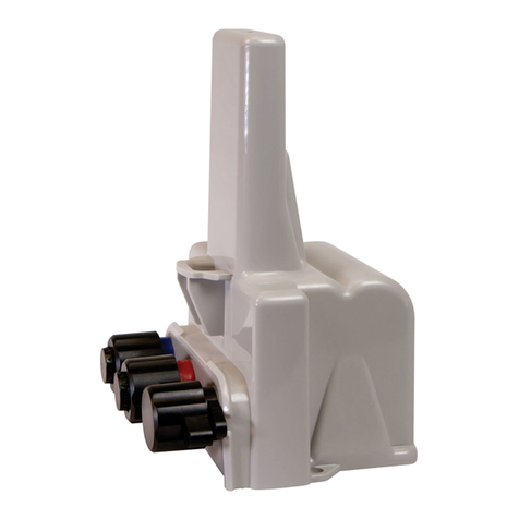
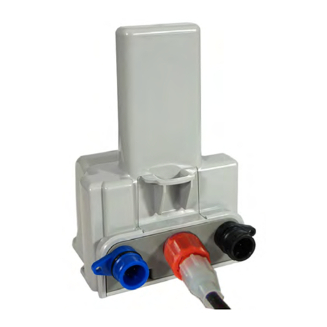
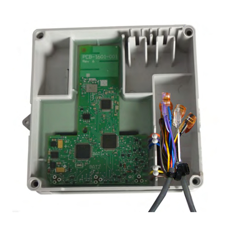
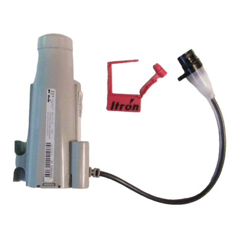
ITRON Cellular 500G User manual

Cellular 500G Module Remote Mount Installation Guide
October 11, 2021
815-0622-00
Copyright © 2021 Itron, Inc. All rights reserved.
Confidentiality Notice
Confidential Information of Itron®, Inc., provided under nondisclosure obligations. The information
contained herein is proprietary and confidential and is being provided subject to the condition that (i) it
be held in confidence except to the extent required otherwise by law and (ii) it will be used only for the
purposes described herein. Any third party that is given access to this information shall be similarly
bound in writing.
Trademark Notice
Itron is a registered trademark of Itron, Inc.
All other product names and logos in this documentation are used for identification purposes only and
may be trademarks or registered trademarks of their respective companies.
For more information about Itron or Itron products, go to www.itron.com.
If you have questions or comments about a software or hardware product, contact Itron Technical
Support Services.
Contact
Email: [email protected]
Itron Access: https://support.itron.com
Telephone Itron Technical Support North America: 1-877-487-6602
For technical support contact information by region, go to www.itron.com and select your country and
language.
October 11, 2021 815-0622-00 REV 000 Itron, Inc. Page 2 of 99
DRAFT

Contents
Cellular500G Module Remote MountInstallation Guide 1
Contents 3
New in This Document 6
1 Introduction 7
Related Documents 7
Security 7
Transmission Modes 8
Mobile High Power Mode 8
Mobile and Handheld Mode 8
(Optional) Hard to Read Mode 9
Highlighted Features 9
Gas Day Take 9
High Flow Event/Alarm 9
Local Auditing 10
Low Battery Event/Alarm 10
Functional Specifications 10
Operational Specifications 11
Firmware Functionality 11
2 Mounting 12
Standard Installation Options 12
Mounting on a Pipe 12
Completing the Installation 13
Adapter Plate Mounting Positions 15
Selecting and Installing On a Wall or Flat Vertical Mounting Location 16
3 Programming 18
Standard Configuration 18
Programming the Cellular 500G Module 18
Itron Programs and Software Variables 19
Field Deployment Manager (FDM) 19
Mercury X-Blank Options 21
Check Endpoint Functions 22
October 11, 2021 815-0622-00 REV 000 Itron, Inc. Page 3 of 99
DRAFT

Field Collection System (FCS) (Mobile Mode Only) 22
OpenWay Collection Manager (OWCM) 22
Itron Enterprise Edition (IEE) Meter Data Management 22
4 Specific Meter Manufacturer Installation 23
Diaphragm Meter Installation 23
Overview 23
Module Mounting 25
Mechanical and Wiring Installation Instructions 25
Programming and Requirements Notes 32
Eagle Research Meter Installation 33
Overview 34
Mounting Instructions 35
Mechanical and Wiring Installation Instructions 36
Programming and Requirements Notes 39
Elster American Meter Installation 44
Overview 44
Mounting Instructions 45
Mechanical and Wiring Installation Instructions 47
Galvanic Gas Micro Installation 49
Overview 50
Mounting Instructions 50
Mechanical and Wiring Installation Instructions 50
Programming Notes 51
GE Oil and Gas Meter Installation 51
Overview 52
Custom Mounting Options 53
Mechanical and Wiring Installation Instructions 56
Programming and Requirements Notes 63
Honeywell Instrument Installation 64
Overview 65
Mounting Instructions 66
Mechanical and Wiring Installation Instructions 68
Programming and Requirements 73
Itron Meter Installation 76
National Meter Installation 77
October 11, 2021 815-0622-00 REV 000 Itron, Inc. Page 4 of 99
Cellular 500G Module Remote Mount Installation Guide Table of Contents
DRAFT

Romet Meter Installation 78
Overview 78
Mounting Instructions 79
Mechanical and Wiring Installation Instructions 81
Programming and Requirements Notes 86
Sensus Meter Installation 89
Overview 89
Mounting Instructions 89
Mechanical and Wiring Installation Instructions 91
Programming and Requirements Notes 91
5 Using Gel-cap Connectors to Complete Wiring Connections 92
6 Optional Sealant Application Instructions 94
A Important Safety and Compliance Information 96
U.S. and Canadian Patent Numbers 96
U.S. Patent Numbers 96
Canadian Patent Numbers 96
USA, FCC Part 15 Spectrum Compliance 96
USA, FCC Class B-Part 15 96
Modifications and Repairs 97
Modifications, Repairs, Installation, and Removal 97
Canada, ISED Spectrum Compliance 97
RF Exposure (FCC/ISED) 98
Transportation Classification 98
Lithium Battery Safety 98
Equipment Repairs 98
Intrinsic Safety 98
Electrostatic Ignition Hazard 99
Module Cleaning 99
Do Not Drop 99
October 11, 2021 815-0622-00 REV 000 Itron, Inc. Page 5 of 99
Cellular 500G Module Remote Mount Installation Guide Table of Contents
DRAFT

New in This Document
Revision Date Description
REV 000 March 2021 First date of publication.
October 11, 2021 815-0622-00 REV 000 Itron, Inc. Page 6 of 99
Cellular 500G Module Remote Mount Installation Guide Table of Contents
DRAFT

1
Introduction
Itron’s Remote Mount Cellular 500G Modules (hereafter referred to as Cellular 500G)are
IPV4/IPv6 open standards-based gas modules designed to be read under Itron’s multi-
purpose Network Mode or by legacy Mobile Mode. In Network Mode. The Cellular 500G offers
firmware download, sub-hourly interval data, and extended data storage. In Mobile Mode. The
Cellular 500G operates identically to the 100G DLS Dataglogging Remote Module. Itron
Cellular 500Gs can be read by legacy handhelds and mobile or the new Itron Mobile Radio
readers. The Cellular 500G continues Itron’s tradition of reliability, accuracy, and long battery
life while supporting the industry’s standards for security and intrinsic safety.
The Cellular 500G features tilt and cut cable-event reporting and security seals to indicate
physical tampering and minimize theft. Cut cable is reported when communications fail
between the meter or instrumentand the Cellular 500G, possibly from a cut or disconnected
cable. The Cellular 500G circuitry senses an electrical current break to report a cut cable
alarm or event.
Related Documents
The following documents may also be helpful, and can be accessed and viewed on Itron
Access (https://access.itron.com).
■500G Modules Ordering Guide
■Cellular 500G Module Specification Sheet
■Cellular 500G Technical Reference Guide
■Field Deployment Manager (FDM)Tools Configuration Guide
■Field Deployment Manager (FDM) Tools Mobile Application Guide
■Gas Module Compatibility Matrix
■OpenWay®Collection Manager Device Interface Guide
Security
TheCellular 500G is a component of Itron’s OpenWay system. The module’s system security,
provided by Itron Security Manager (ISM), applies to the RF communications between the
collection device and the module.
There are two fundamental security processes used in the Itron Security Manager to ensure
system communication confidentiality and validity.
October 11, 2021 815-0622-00 REV 000 Itron, Inc. Page 7 of 99
DRAFT

■Authentication. Authentication is the process of confirming that an artifact is genuine or
valid. Authentication in the module is the process of verifying a request is from a valid
source and in its original form.
■Encryption. Encryption is the process of transforming information to make it unreadable
to anyone who does not have a valid security key. There are two types of encryption,
symmetric and asymmetric. Symmetric encryption uses a shared key to decrypt or encrypt
information. Asymmetric encryption uses a private key to encrypt and a public key to
decrypt. Data transmissions over the network are protected using AES-256 encryption.
As a component of the Itron OpenWay solution, the module supports the security model found
in the OpenWay solution for both reading and programming. If the modules are shipped
without security enabled (ready to secure), the utility can—at a later date—configure the
modules for ISM enhanced security.
Important! Modules ordered pre-programmed with security injected and specified
as Zero Touch Deployment require that the installer rotates the wriggler five (5)
times to activate the module to join the network if the module is installed in a location
with little or no gas flow.
Transmission Modes
In Network Mode, the module provides 3,840 buckets of configurable interval data. Interval
options are 5, 15, 30, or 60 minutes.
Note: Interval data options are dependent on the module’s firmware version. For more
information, see Firmware Functionality on page 11.
Output power in Network Mode is designed to transmit three times a day with a 20-year
battery life.
In Mobile Mode, the module provides 960 buckets of hourly interval data and can be set to
transmit in mobile and handheld, hard to read mobile and handheld. Mobile Mode
transmission modes include the following transmission characteristics:
Mobile High Power Mode
The module transmits a high-powered Radio Frequency (RF) message every 60 seconds. In
Mobile High Power Mode, the expected battery life is 20 years.
Mobile and Handheld Mode
The module transmits a medium-powered RF message every 15 seconds. In Mobile and
Handheld Mode, the expected battery life is 20 years.
Cellular 500G Module Remote Mount Installation Guide 1 Introduction
October 11, 2021 815-0622-00 REV 000 Itron, Inc. Page 8 of 99
DRAFT

(Optional) Hard to Read Mode
The module transmits a high-powered RF message every 30 seconds. In Hard to Read Mode,
the expected battery life decreases to 15 years in this mode. The hard to read mobile mode
should only be used for exceptionally hard-to-read applications (such as meters installed on
rooftops or in sub-basements).
Caution: If you perform a switch to Network Mode or Switch to Mobile Mode
operation, it results in a loss of interval data.
Neither an ISEDnor an FCC license is not required to read the modules.
Highlighted Features
The following sections describe highlighted features in theItron gas modules (these features
vary by module type and installed firmware).
Gas Day Take
Note: Gas Day Take functionality is dependent on the Cellular 500G firmware version. For
more information, see Firmware Functionality on page 11.
Gas Day Take (GDT) is critical to many natural gas utilities. GDT allows utilities to manage
deregulated gas purchases. While daily GDT reads can be used for various operations within
the utility, the primary time constrained business operation is to daily balance deregulated
(transport) customers. GDT requires GDT data from a percentage (typically a maximum of
10%) of the utility’s customers at 9:00 AM Central Clock Time (CCT).
All collected data must be prepared and presented to deregulated marketers and customers
by 11:00 AM CCT to support the gas utility’s deregulated tariff. If a deregulated marketer or
customer under- or over-burns what they nominated for a given day, they may pay a daily
penalty. Customers require the previous day’s GDT data to make adjustments to their next
day nomination to avoid penalties.
High Flow Event/Alarm
Note: High Flow event functionality is dependent on the module's firmware version. For
more information, see Firmware Functionality on page 11.
High Flow is a configurable event/alarm that can alert a utility of an excessive flow of gas to
avoid potential hazardous events. The High Flow threshold can be configured using Field
Deployment Manager (FDM) Tools for the OpenWay Collection Manager (OWCM) for
OpenWay modules.
Cellular 500G Module Remote Mount Installation Guide 1 Introduction
October 11, 2021 815-0622-00 REV 000 Itron, Inc. Page 9 of 99
DRAFT

Local Auditing
Note: Local auditing functionality is dependent on the module’s firmware version. For
more information, see Firmware Functionality on page 11.
The Cellular 500G supports local data auditing of installation programming. Local auditing
features the listed characteristics.
■Supports writing data (in both manufacturing and by FDM) to the module to support future
installation programming auditing.
■Reading the auditing data is supported locally.
■Auditing parameters include FDM User ID, number of dials, meter drive rate, unit of
measure, count rate, rollover, and PComp.
■Timestamping of auditing parameters.
■Log access via Companion Specification for Energy Metering (COSEM) only.
Low Battery Event/Alarm
Note: For Cellular 500Gs, low-battery functionality is dependent on the module’s firmware
version. For more information, see Firmware Functionality on page 11.
The Cellular 500Gs’ low-battery events are flagged when the device reaches a 10% of battery
life remaining state. The event triggers an alarm configurable for asynchronous delivery to the
head end system.
Functional Specifications
Functional
specification
Description
Power source Single “D” cell lithium batteries
Tamper
detection
Tilt and cut cable
Regulatory and
standards
FCC compliance: Part 15.247, 15.249 (programming), 15.109
FCC IDs:
■EWQ500C: for Remote Mount
■EWQ500GAC: for American/Rockwell Gas meters
■The Cellular modem is a Sierra Wireless HL7800 module
–FCC ID: NLNHL78
ISED compliance: RSS-247, RSS-210 (programming), ICES 003
■IC: 864D-50)C: for Remote Mount
■IC: 864D-500GAC: American/Rockwell
Cellular 500G Module Remote Mount Installation Guide 1 Introduction
October 11, 2021 815-0622-00 REV 000 Itron, Inc. Page 10 of 99
DRAFT

Functional
specification
Description
■The Cellular modem is a Sierra Wireless HL7800 module.
–IC: 2417C-HL78
Measurement Canada: Pending
Intrinsically safe
per
Telemetering Equipment for use in Hazardous Locations, for Cl I, Div 1, Gp D for Haz Loc,
Temp Code T1, -40°C ≤ Ta ≤ +70°C.
Operational All Cellular 500Gs operate pursuant to FCC, ISED cellular licensing, and 3GPP defined,
regulated cellular standards and networks.
Frequency: 3GPP Band 4 (744-787 MHz)/Band 13 (1710-2155 MHz) for cellular
operation; 902 to 928 MHz and 2400-2483.5 MHz ISM bands for RF operation.
Program frequency: 908 MHz
Product
identification
Numeric and bar coded ERT type and serial number
Construction
materials
Gray polycarbonate housing and back plate with encapsulated electronics
Operational Specifications
Operational specifications Description
Operating temperatures -40° to 158° F (-40° to +70° C)
Operating humidity 5 to 95% relative humidity
Data integrity Verified in every data message
Firmware Functionality
This section lists the Cellular 500G device firmware information and lists functionality by
version.
Part Number Global
Software
Release
(GSR)
Version
FDM Check
Endpoint
Firmware
Version
Over-the-Air
Firmware Part
Number
Firmware Functionality
FMW-xxxx-
xxx1601-004
[4.4.2]
4.15.4 1.3.74.4.0 DFW-xxx-xxx ■Initial firmware release
■IPv6 Addressable
■Network Mode
■Mobile Mode
■60 minute interval data
Cellular 500G Module Remote Mount Installation Guide 1 Introduction
October 11, 2021 815-0622-00 REV 000 Itron, Inc. Page 11 of 99
DRAFT

2
Mounting
This chapter provides the instructions to mount the Cellular 500G on a pipe or other flat
vertical surface (wall).
Standard Installation Options
Mount the Cellular 500G using the pipe mount or wall mount (flat vertical surface) procedure.
■Pipe mount. Itron offers a pipe installation kit (CFG-0005-003) to mount the Cellular 500G
on a pipe.
■Flat vertical (wall) mount. Installation using the wall mount option places the module on
a wall or other vertical surface.
Select the mounting option that will best work for your system. For example, your setup may
provide the location for a pipe mount but not a wall mounto the preferred mounting location is
near the meter or instrument, but some installations may require an extended cable length.
For example, your installation may require mounting the module around a corner to avoid RF
interference. The Cellular 500G supports cable lengths up to 300 feet with a recommended
one-splice limitation. Installers must mount the Cellular 500G in a vertical position with the
label directional arrow pointed upward.
Warning! Do not mount the Cellular 500G in an orientation other than vertical
(Cellular 500G label arrow pointed upward). Violating the mounting orientation
requirements may void the product warranty.
Upright vertical positioning is critical because:
■The modules are optimized for communication and require upright mounting. Any other
mounting position could result in reduced RF performance.
■The Cellular 500G tilt tamper sensor requires upright mounting. Any other mounting
position can cause issues with the module's tilt tamper detection.
Mounting on a Pipe
The following items are required to mount the Cellular 500G on a pipe.
October 11, 2021 815-0622-00 REV 000 Itron, Inc. Page 12 of 99
DRAFT

Itron part number Description
CFG-0005-003 Pipe mount kit contents:
■2 band clamps
■2 tamper seals
■1 pipe bracket
■2 cable ties
■1 adapter plate
■the following screws:
1. SCR-0215-001 (2) #8-16 by 1/2 inch slotted pan-head
tapping screw, corrosion-resistant steel. Attaches the
adapter plate to the pipe bracket.
2. SCR-0215-002 (2) #8-16 by 1 inch slotted pan-head
tapping screw, corrosion-resistant steel. Attaches the
module to the adapter plate.
Completing the Installation
1. Remove the pipe bracket and clamp from the kit.
2.
3. Push the end of the clamp’s band through the holes in the pipe bracket as shown.
4. Place the band clamp around the pipe. The band will loosely wrap around the pipe.
Cellular 500G Module Remote Mount Installation Guide 2 Mounting
October 11, 2021 815-0622-00 REV 000 Itron, Inc. Page 13 of 99
DRAFT

Push the end of the band through the band clamp screw assembly.
Turn the band clamp’s screw assembly to fit into the pipe bracket opening.
Tighten the clamp screw until the band clamp is secure on the pipe.
5. Place the adapter plate on the pipe bracket with the mounting lug at the top. The adapter
plate screw bosses fit into the pipe bracket recess.
6. Ensure that the adapter plate is positioned as shown with the mounting lug (1) at the top.
Install the adapter plate on the pipe mounting bracket, use the two shortest (1/2 inch)
screws from the pipe mount kit.
Place the mounting screws into the holes as shown (2).
Tighten both screws in an alternating pattern to 9 to 12 inch-pounds torque.
7. Position the back on the Cellular 500G against the face of the adapter plate. The adapter
plate mounting lug must be positioned above the module mounting lug recess.
8. Push up on the module until the adapter plate mounting lug is as far as possible inside the
module mounting lug recess.
9. Align the module backplate mounting holes with the pipe mount adapter plate holes. Install
the 2 one inch module mounting screws from the installation kit. Tighten the module
mounting screws evenly in an alternating pattern. Tighten the screws to 9 to 12 inch-
pounds torque.
Cellular 500G Module Remote Mount Installation Guide 2 Mounting
October 11, 2021 815-0622-00 REV 000 Itron, Inc. Page 14 of 99
DRAFT

10. Insert the tamper seals.
11. Gather the excess module cabling into a loop and use the cable tie to secure the gathered
cable to the pipe.
Adapter Plate Mounting Positions
Note: The notch at the top of the adapter plate (1) must always be at the top position. The
following illustrations show the various mounting configurations. The adapter plate
mounting screw locations are indicated (2).
45-degree angle with the pipe
running to the right
45-degree angle with the pipe running
to the left
Horizontal
Cellular 500G Module Remote Mount Installation Guide 2 Mounting
October 11, 2021 815-0622-00 REV 000 Itron, Inc. Page 15 of 99
DRAFT

Selecting and Installing On a Wall or Flat Vertical Mounting
Location
Carefully select a mounting location free from electrical wires. The mounting location must
have the proper clearance to accommodate the 1.5 inch module mounting screws so nothing
is damaged by the drill or mounting screws. Use a compatible mounting screw.
1. Drill three pilot holes in the mounting surface. The drilled pilot holes for the two bottom
screws must be on a horizontal line.
a. 3 inches
b. 11/16inches
c. 3/8inches
2. Screw the top mounting screw into the top pilot hole drilled in step 1, leaving enough of the
screw protruding so the module lug recess on the back plate slides over the screw head
and fits completely into the lug recess. Make adjustments as necessary.
3. Install the two bottom mounting screws. Tighten the screws in an alternating pattern to
secure the module firmly in position.
4. Place a new tamper seal over each bottom module mounting screw as required.
Cellular 500G Module Remote Mount Installation Guide 2 Mounting
October 11, 2021 815-0622-00 REV 000 Itron, Inc. Page 16 of 99
DRAFT

5. Secure any excess module cabling with a cable tie.
Cellular 500G Module Remote Mount Installation Guide 2 Mounting
October 11, 2021 815-0622-00 REV 000 Itron, Inc. Page 17 of 99
DRAFT

3
Programming
Caution: You must program the module before use.
Programming Itron modules requires an understanding of:
■Your meter’s drive rate and the number of dials
–The drive rate and number of dials is important for programming the module to count
correctly and roll over to zero at the correct time. For example, a four-dial, two cubic
feet meter configuration will count two cubic-feet for each rotation and roll over to zero
after 9999.99 where the ones place is equivalent to 100 cubic-feet.
■How your system interprets the meter reading
–Some systems modify the consumption reading with the collection software. Other
times, the billing system is used to make modifications. If modifications are made in
both systems, issues may cause consumption reading errors.
It is important to understand your system before the modules are programmed.
Program the module in Network Mode using a compatible programming device loaded with
FDM version 4.1 or higher.
Program the module in Mobile Mode using an approved programming device loaded with
Field Deployment Manager (FDM) software version 4.4 or later.
Standard Configuration
Gas modules are capable of configurations that reduce battery life. Standard battery life is
based on the following configuration:
■Hourly interval data
■Interrogations of three times per day
■60 second receiver wakeup
■Five firmware downloads over the life of the module
■Network management and security overhead set to default timing
■RF at capacity (2,000 maximum per cell)
■Average of one two-way command/response per week
Programming the Cellular 500G Module
Program the meter drive rate into the Cellular 500G using a compatible programming device.
October 11, 2021 815-0622-00 REV 000 Itron, Inc. Page 18 of 99
DRAFT

1. Verify that you have the correct programming mode (Network Mode or Mobile Mode
[mobile high power mode, mobile/handheld mode, or hard-to-read mode]) for your
application.
2. For all programming and Check Endpoint operations using a handheld computer, hold
the handheld as close to vertical as possible. For best success, keep the handheld within
six feet of the target module.
3. Programming parameters are based on the configuration file loaded into the programming
device.
4. Read or Check the Cellular 500G using a compatible handheld computer.
–If the read result is higher than the number programmed in step 1, the module is
counting correctly.
–If the read result is not higher than the number programmed in step 1, replace the
Cellular 500G.
Itron Programs and Software Variables
This section defines and clarifies possible system variables you may encounter in
programming modules.
Field Deployment Manager (FDM)
The following tables illustrate various FDM programming configurations and the endpoint
response to each setting.
Cellular 500G Module Remote Mount Installation Guide 3 Programming
October 11, 2021 815-0622-00 REV 000 Itron, Inc. Page 19 of 99
DRAFT

Cellular 500G Module Remote Mount Installation Guide 3 Programming
October 11, 2021 815-0622-00 REV 000 Itron, Inc. Page 20 of 99
DRAFT
Table of contents
Other ITRON Control Unit manuals

ITRON
ITRON OpenWay Riva User manual

ITRON
ITRON OpenWay Riva User manual

ITRON
ITRON 100G User manual

ITRON
ITRON ERT 40W User manual

ITRON
ITRON 100W-R User manual

ITRON
ITRON OpenWay Riva User manual

ITRON
ITRON OpenWay Riva User manual

ITRON
ITRON EquaScan hMIURFV2 User manual

ITRON
ITRON 022 User manual

ITRON
ITRON OpenWay Riva User manual

ITRON
ITRON 800 Series User manual

ITRON
ITRON OpenWay Riva 500W ERT User manual
ITRON
ITRON ACT1 User manual

ITRON
ITRON ITR9002 Use and care manual

ITRON
ITRON 100G User manual

ITRON
ITRON 8600 Series User manual

ITRON
ITRON OpenWay Riva 500W ERT User manual

ITRON
ITRON OpenWay Riva User manual
ITRON
ITRON 60W Endpoint User manual

ITRON
ITRON OpenWay Riva 500W ERT User manual