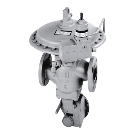
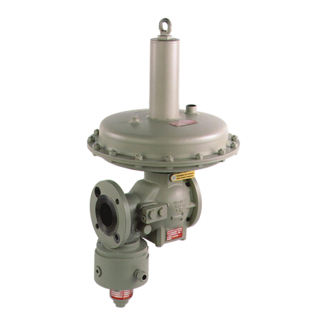
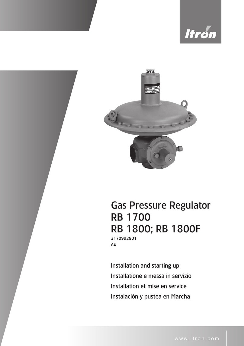
ITRON 133 User manual

www.itron.com
Gasdruckregler
Gas Pressure Regulator
Régulateur de pression
Gasdrukregelaar
Ðåãóëÿòîð äàâëåíèÿ ãàçà
Regulátor tlaku plynu
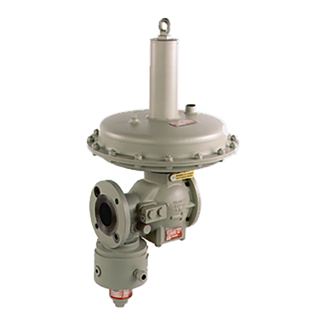
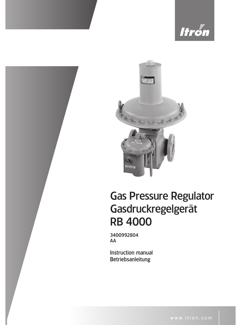
Type 133/233 & 244
115-099-2802
AC
Betriebsanleitung
Instruction Manual
Mode d’emploi
Bedieningsvoorschrift
Ðóêîâîäñòâî ïî ýêñïëóàòàöèè
Návod k obsluze

22
Inhaltsverzeichnis / Contents / Contenu / Inhoudsopgave / Ñîäåðæàíèå / Obsah
Seite
Page
Pagina
Ñòðàíèöà
Strana
DE Schematische Darstellung Regelgerät 133 / 233 und 244.....................3 - 5
Technische Daten / Typ-Auswahl ..........................................6
Führungsbereiche Regler und SAVs ........................................7
Einbauanleitung, Regler- / SAV-Inbetriebnahme ............................8 - 9
Sicherheitshinweise ...............................................10 – 11
Abmessungen / Einbaumaße ............................................42
Beispiele für Montagepositionen ..........................................45
Installationsbeispiel ....................................................46
GB Schematic section Regulator 133 / 233 and 244............................3 – 5
Technical data / Type selection...........................................12
Spring range Regulator and SSV..........................................13
Installation and start-up instructions of Regulator and SSV ..................14 – 15
Safety instructions ................................................16 – 17
Dimension ..........................................................42
Example of assembly position............................................45
Example of installation .................................................46
FR Représentation schématique du régulateur 133 / 233 et 244 ..................3 – 5
Caractéristiques techniques / choix du type .................................18
Gammes de pression régulateur et vanne de sécurité ..........................19
Instructions de montage, mise en service régulateur et vannes de sécurité ......21 – 22
Conseils de sécurité ...............................................23 – 24
Dimensions / encombrement ............................................43
Positions de montage ..................................................45
Exemple d’installation ..................................................46
NL Doorsnede tekening regelaar 133 / 233 en 244.............................3 – 5
Technische data / Type selectie ..........................................24
Veerbereik regelaar en afslagveiligheid SSV..................................25
Installatie en opstart instructie voor regelaar en afslagveiligheid SSV . . . . . . . . . . . 26 – 27
Veiligheids instructie ...............................................28 – 29
Afmetingen ......................................................... 43
Voorbeeld van behuizings positie ........................................ 45
Voorbeeld installatie .................................................. 46
RU Ñõåìàòè÷åñêîå ïðåäñòàâëåíèå ÓÐÄà 133 / 233 è 244.................... 3 – 5
Òåõíè÷åñêèå õàðàêòåðèñòèêè / Âûáîð òèïà ..............................30
Äèàïàçîíû âûõîäíîãî äàâëåíèÿ ðåãóëÿòîðà è ÏÊÎ .......................31
Èíñòðóêöèÿ ïî ìîíòàæó, ââîä ðåãóëÿòîðà è ÏÊÎ â ýêñïëóàòàöèþ .......32 – 33
Óêàçàíèÿ ïî òåõíèêå áåçîïàñíîñòè .................................34 – 35
Ãàáàðèòíûå ðàçìåðû / Ìîíòàæíûå ðàçìåðû ............................43
Ïðèìåðû äëÿ ìîíòàæíûõ ïîëîæåíèé ...................................45
Ïðèìåð èíñòàëëÿöèè.................................................46
CZ Schematická znázornění regulátoru 133 / 233 a 244.........................3 – 5
Technické údaje / Volba typu ............................................36
Rozsah pružiny regulátoru a bezpečnostního rychlouzávěru .....................37
Pokyny k montáži a zprovoznění regulátoru a bezpečnostního rychlouzávěru ....38 – 39
Bezpečnostní pokyny a ES Prohlášení o shodě...........................40 – 41
Rozměry............................................................44
Příklad montážních poloh ...............................................45
Příklad montáže ......................................................46
33
Regler / Regulator / Régulateur / Regelaar / Ðåãóëÿòîð / Regulátor
133-72, DN 25
Schematische Darstellung / Sectional view, / Représentation schématique /
Doorsnede tekening / Ñõåìàòè÷åñêîå ïðåäñòàâëåíèå / Schematické
znázornění
Atmungsanschluss, siehe Seite 8
Breathing line connection, see page 14
Raccordement évent, voir page 20
Ademopenings aansluiting zie pagina 26
Ïðèñîåäèíåíèå äûõàòåëüíîé ëèíèè, ñì.
ñòð. 32
Přípojka odvzdušňovacího potrubí, viz str. 8
Anschluss für Fremdimpuls
External sensing line connection
Raccordement d’impulsation
Aansluiting buitenimpuls
Ïðèñîåäèíåíèå äëÿ âíåøíåãî èìïóëüñà
Přípojka externího snímacího vedení
Anschluss für Fremdimpuls
External sensing line connection
Raccordement d’impulsation
Aansluiting buitenimpuls
Ïðèñîåäèíåíèå äëÿ âíåøíåãî èìïóëüñà
Přípojka externího snímacího vedení

44
Regler / Regulator / Régulateur / Regelaar / Ðåãóëÿòîð / Regulátor
233-12-4-66, DN 50
Schematische Darstellung / Sectional view / Représentation schématique /
Doorsnede tekening / Ñõåìàòè÷åñêîå ïðåäñòàâëåíèå / Schematické
znázornění
Anschluss für Fremdimpuls
External sensing line connection
Raccordement d’impulsation
Aansluiting buitenimpuls
Ïðèñîåäèíåíèå äëÿ âíåøíåãî èìïóëüñà
Přípojka externího snímacího vedení
Anschluss für Fremdimpuls
External sensing line connection
Raccordement d’impulsation
Aansluiting buitenimpuls
Ïðèñîåäèíåíèå äëÿ âíåøíåãî èìïóëüñà
Přípojka externího snímacího vedení
Atmungsanschluss, siehe Seite 8
Breathing line connection, see page 14
Raccordement évent, voir page 20
Ademopenings aansluiting zie pagina 26
Ïðèñîåäèíåíèå äûõàòåëüíîé ëèíèè,
ñì. ñòð. 32
Přípojka odvzdušňovacího potrubí, viz str. 8

55
Regler / Regulator / Régulateur / Regelaar / Ðåãóëÿòîð / Regulátor
244-12-4-72, DN 50
Schematische Darstellung / Sectional view / Représentation schématique /
Doorsnede tekening/ Ñõåìàòè÷åñêîå ïðåäñòàâëåíèå /
Schematické znázornění
Atmungsanschluss, siehe Seite 8
Breathing line connection, see page 14
Raccordement évent, voir page 20
Ademopenings aansluiting zie pagina 26
Ïðèñîåäèíåíèå äûõàòåëüíîé ëèíèè, ñì. ñòð. 32
Anschluss für Fremdimpuls
External sensing line connection
Raccordement d’impulsation
Aansluiting buitenimpuls
Ïðèñîåäèíåíèå äëÿ âíåøíåãî èìïóëüñà
Přípojka externího snímacího vedení
Anschluss für Fremdimpuls
External sensing line connection
Raccordement d’impulsation
Aansluiting buitenimpuls
Ïðèñîåäèíåíèå äëÿ âíåøíåãî èìïóëüñà
Přípojka externího snímacího vedení

6
Technische Daten / Typenbezeichnung Regelgerät 133 / 233 und 244
Nennweite DN 251), DN 40, DN 50
Anschluss Flansch: PN 16 / DIN 2633
Gewinde: G 3/4, G 1, G1 1/22), ISO 228/1,Rp 3/4
DIN 2999; 3/4-, 1”- & 1 1/22)-NPT;-BSPT,
Außengewinde für Rohrverschraubung
nach DIN 2993: G1 1/21), nach ISO 228/1,
Einstutzen-Anschluss nach DIN 3376/21),
mit Ü-Mutter UB 25: DN 25 (R2”, Form B)
Druckstufen PN 1 133-...,133E-..., 233/244 -8 /-12-…
PN 4 (5), 6 & 8 133-...-..., 233 -8 /-12-…
PN 4 244 -8-…/-12-…-…
Eingangsdruck PN 1 pu = 0,05 - 1,0 bar
PN 4 (5), 6 & 8 pu = 0,35 - 4,0 (5,0; 6,0; 8,0 3,4)) bar
Ausgangsdruckbereich wd = 0,01 – 0,7 bar
Betriebstemperatur -20 - +60°C
Umgebungstemperatur -30 - +60°C
Durchfluss Vn ca. 60 (133) / 400 (233) Nm3/h Erdgas
Typenbezeichnung 133-/133E-… 133-4(5)-... 133-6
233-12/8- 233-12/8-4(5)-… 233-12/8-6...
244-12/8-… 244-12/8-4-…
• mit SAV für obere Abschaltung (pdo ≥ 400mbar) -61 -61 –
• mit SAV für obere. Abschaltung und SBV
(pdo ≥ 400mbar) -62 -62 –
• mit SAV für obere & untere Abschaltung -64 -
• mit SAV für obere & untere Abschaltung & SBV -66 -66 - 66
• mit SAV für obere Abschaltung und
Sicherheitsmembrane (pdo ≥ 400mbar) PN 1 -630 – –
• mit SAV für obere und untere Abschaltung und
Sicherheitsmembrane (pdo ≥ 400mbar) PN 1 -650 – –
• mit SAV für obere Abschaltung (pdo ≤ 450mbar) -71 -71 –
• mit SAV für obere. Abschaltung & SBV
(pdo ≤ 450mbar) -72 -72 –
• mit SAV für obere Abschaltung und
Sicherheitsmembrane (pdo ≤ 450mbar) PN 1 -730 – –
SAV-Ausführungen:
-6.. = SAV I, II
-7.. = SAV 033
1) nur Regler 133
2) nur Regler 233
3) >PN 4 immer mit Fremdimpuls
4) max. Düsendurchmesser beachten!

7
Führungsbereiche für Ausgangsdruck pd
Regelgerät Typ Führungsbereich Wds Teilnummer Draht-Ø Farbe
133 mit Gasmangelsi-
cherung
9-15 mbar
14-20 mbar
18-26 mbar
24-40 mbar
38-53 mbar
955-200-08
955-200-09
955-201-06
955-202-98
955-200-11
1,6 mm
1,8
2,25
2,5
2,4
rot
blau
silber
gelb
orange
133 8-16 mbar
12-20 mbar
15-35 mbar
30-70 mbar
50-140 mbar
100-210 mbar
955-200-08
955-200-09
955-200-10
955-200-11
955-200-12
955-200-83
1,6 mm
1,8
2,0
2,4
3,0
3,4
rot
blau
grün
orange
schw.-weiß
silber
133 HP 140 – 420 mbar 955-200-84 4,5 mm schwarz
233-12 / 244-12 8-16 mbar
12-20 mbar
15-35 mbar
30-70 mbar
70-140 mbar
100-210 mbar
955-200-13
955-200-14
955-200-15
955-200-16
955-200-17
955-200-18
2,8
3,2
3,6
4,5
5,6
6,3
rot
blau
grün
orange
schwarz
silber (blank)
233-8 / 244-8 30-70 mbar
70-140 mbar
140-300 mbar
210-450 mbar
955-200-15
955-200-16
955-200-17
955-200-18
3,6 mm
4,5
5,6
6,3
grün
orange
schw.-weiß
silber (blank)
233-8 HP 420-700 mbar 955-200-69+
955-200-18
4,0 mm
6,3
silber
silber (blank)
Führungsbereiche für SAV 033, obere Abschaltung Pdo
Abschaltung bei Führungsbereich
Wdso Teilnummer Draht-Ø Farbe
Druckanstieg
Pdso
40-70 mbar
50-150 mbar
140-450 mbar
955-200-22
955-200-23
955-200-24
1,4 mm
1,6
2,6
rot
blau
grün
Führungsbereiche für SAV I und II obere und untere Abschaltung
Abschaltung bei Führungsbereich
Wdso / Wdsu Teilnummer Draht-Ø Farbe
Druckanstieg
Pdso
20-60 mbar
50-120 mbar
100-400 mbar
300-600 mbar
400-1000 mbar
955-200-22
955-200-23
955-200-24
955-200-52
955-202-42
1,4 mm
1,6
2,6
2,8
3,2
rot
blau
grün
braun
silber
Druckmangel Pdsu 8-50 mbar 955-200-32 0,9 mm rot
Zur Beachtung: ∆p zwischen pds und pdso max 150 mbar!
Regelgruppe AC & Schließdruckgruppe SG: Abschaltdruckgruppe (SAV):
Ausgangsdruck AC SG Wdo AG
8 - 20 mbar 20 30 20 – 400 mbar 10
>20 - 40 mbar 10 20 0,4 – 1,0 bar 5
>40 - 700 mbar 5 10 Wdu AG
8 – 20 mbar 30
20 – 50 mbar 10

8
Installation
• Der maximale Eingangsdruck in der Anlage
darf nicht höher sein als der max. zulässige
Eingangsdruck des Reglers.
• Zur Installation muss ein genügend großer
Bauraum vorhanden sein.
Vor Installation des Regelgeräts in das Leitungs-
system ist zu beachten, dass
• Die Anschlussflansche beider Seiten parallel
angeordnet sind,
• Eingangs- und Ausgangsleitung frei von jeg-
lichen Verunreinigungen, wie Sand, Schweiß-
reste usw. sind,
• Das Gerät keine sichtbaren Beschädigungen
aufweist,
• Die Ein- und Ausgangsöffnungen des Ventil-
körpers absolut sauber sind,
• Die Gasdurchflussrichtung muß mit dem auf
dem Gerät angebrachten Pfeil übereinstim-
men.
Einbaulage
• Die Einbaulage des Gas-Druckregelgerätes ist
frei wählbar.
Impulsleitung
• Nicht erforderlich bei internem Impulsabgriff
< 4,0 bar),
• Bei Fremdimpuls (> 4,0 bar) ist die Impulslei-
tung (Rückführleitung) an einem turbulenzfrei-
en Rohrstück mit etwa 5D, vorzugsweise in
einem geraden Bereich der Ausgangsleitung
anzuschließen.
• Anschluss: G1/2“/EO-12 (Regler)
• Anschluss: G1/4“/EO-6 (SAV)
• Ermeto-Rohr EO-12 / -6, Stahl verzinkt
Atmungsleitung
• Atmungsanschluss Typ 133: G 3/4“
• Atmungsanschluss Typ 233 / 244: G 1“
• Der Atmungsanschluss am Regelgerät ist zur
Sicherstellung für schnelle Lastwechsel an
folgende Leitungsquerschnitte anzuschließen:
DN 20 bis 3m Atmungsleitung
DN 25 oder größer, über 3m Atmungsleitung
Regler-Inbetriebnahme
Nach Installation des Druckreglers in der Regel-
anlage ist sicherzustellen, dass das Absperrventil
auf der Ein- und Ausgangsseite geschlossen ist.
• Absperrventil auf der Eingangsseite langsam
und vollständig öffnen.
• SAV langsam aufziehen (öffnen), bis es in Of-
fenstellung bleibt und sich Schließdruck bei
dem Regler einstellt (siehe auch Seite 9).
• Absperrventil auf der Ausgangsseite langsam
und vollständig öffnen, bis sich gleichmäßiger
Verbrauch einstellt.
Regler- und SAV-Einstellung
• Der Druckregler wird entsprechend den im
Bestellauftrag festgelegten Spezifikationen
ausgeliefert.
Wenn der eingestellte Ausgangsdruck / SAV-
Abschaltdruck verändert werden soll, ist wie folgt
vorzugehen:
• Zur Erhöhung des Ausgangs-/ Abschalt-
drucks: Die Justierschraube muss mit dem
Justierschlüssel im Uhrzeigersinn gedreht wer-
den.
• Zur Reduzierung des Ausgangs-/ Abschalt-
drucks: Vorgehensweise wie oben; Drehrich-
tung jedoch entgegen dem Uhrzeigersinn.

9
c
d
ab
Verschlusskappe (b) abschrauben und auf Ventilstange (a) aufschrauben. Ventilstange langsam
herausziehen, bis sich Ausgangsdruck im Regelgerät einstellt, das Hebelsystem des SAV’s ein-
rastet und die Ventilstange in Offenstellung bleibt. Nur möglich, wenn der im Regelgerät sich
einstellende Ausgangsdruck kleiner pdso und größer pdsu ist!
Verschlusskappe (b) anschließend wieder aufschrauben.
Inbetriebnahme SAV 033 / SAV-I (obere Abschaltung)
Verschlusskappe (b) abschrauben und auf Ventilstange (a) aufschrauben. Ventilstange langsam
herausziehen, bis das Hebelsystem des SAV’s einrastet. Nur möglich, wenn der im Regelge-
rät sich einstellende Ausgangsdruck kleiner pdso ist! Verschlusskappe anschließend wieder
aufschrauben.
Inbetriebnahme SAV-II (obere und untere Abschaltung)
Wartung und Reparaturen
Alle Arbeiten am Regelgerät sind nur im druck-
losen Zustand durchzuführen. Die Sicherheits-
vorschriften, insbesondere die UVV’s, sowie die
DVGW-Arbeitsblätter G 490, G 491 und G 495
sind zu beachten:
• Absperrventil auf der Ein- und Ausgangsseite ist
zu schließen
• Der Druck muss über das Entlüftungsventil auf
der Ausgangsseite des Druckreglers bis auf das
Nullniveau geführt werden
Achtung
Vor Demontage des Regelgerätes
ist die Einstellfeder mittels Justier-
schlüssel zu entspannen!
Justier- und Düsenwechsel-
schlüssel
Justierschlüssel
Regler 133 Justierschlüssel SW 13
(6-knt)
Regler 233/244 Justierschlüssel SW 1⁄2“
(4-knt)
SAV 033 Justierschlüssel SW 13 (6-knt)
SAV-I Justierschlüssel SW 13 (6-knt)
SAV-II Justierschlüssel SW 13 (6-knt)
und Schraubendreher, Größe 2
(Pos. c und d)
Schlüssel für Düsenwechsel (6-knt)
Regler 133 Düsenschlüssel SW 25
Regler 233/ 244*)
Düsenschlüssel SW 41
*) für Regelgerät Typ 244 immer eine Düsengröße (27,5 mm)!

10
Sicherheitshinweise
• Diese Betriebsanleitung muss leicht zugänglich aufbewahrt werden.
• Nur für saubere und trockene Gase verwenden. Bei aggressiven Medien kontaktieren Sie bitte Itron
für Spezialausführungen.
Auf keinen Fall bei Sauerstoff anwenden: Explosionsgefahr!
• Die nationalen Vorschriften für die Inbetriebnahme, den Betrieb, Prüfungen und die Wartung von Gas-
geräten müssen eingehalten werden.
• Geräte sollten nur an den vorgesehenen Trag-Ösen, oder mittels Tragegurte am Ventilkörper ange-
hoben werden.
• Das Gerät sollte vor der Montage auf eventuelle Transportschäden untersucht werden und darf nur
in einwandfreiem Zustand montiert werden. Eventuelle Lackbeschädigungen sollten nachgebessert
werden. Die Dichtflächen der Flansche müssen beschädigungsfrei und sauber sein.
• Zum Warten und Bedienen ist ausreichend Bauraum vorzusehen.
• Das Gerät ist so zu installieren, dass es in seiner Funktion nicht durch andere Installationskomponenten
beeinträchtigt wird.
• Die angegebenen Anzugsdrehmomente der Schrauben sollten nicht überschritten werden. Die
Schrauben für die Flanschverbindung müssen der Flanschgröße entsprechen und für den Tempera-
turbereich des Gerätes ausgelegt sein. Die Schrauben sind über kreuz anzuziehen.
• Die Länge der bei Flanschverbindungen eingesetzten Schrauben muss so gewählt werden, dass die
Schrauben mindestens einen Gewindegang über die Muttern hinausragen.
• Das Gerät muss spannungsfrei in die Rohrleitung eingebaut werden und die in der Tabelle angege-
benen Anzugsmomente (für die Schrauben Festigkeitsklasse 5.6) dürfen nicht überschritten werden:
Innengewinde
3⁄4 / 1“ / 1 1⁄2“
DIN 2999/ISO 7
Außengewinde
1 1⁄2“ DIN 2993
Flansch
DN 25
Flansch
DN 40
Flansch
DN 50
PN16
PS = 8 bar
80 / 110 / 140
Nm
140 Nm 35 Nm
(M12)
85 Nm
(M16)
85 Nm
(M16)
ANSII50
PS = 8 bar
80 / 110 / 140
Nm
140 Nm 55 Nm
(M14)
55 Nm
(M14)
85 Nm
(M16)
Diese Anzugsmomente sind pro Schraube und gelten für Metallweichstoffdichtungen (mit den
Kenndaten k0 x KD = 45 x bD und k1 = 2,2 x bD). Andere Dichtungen können andere Anzugs-
momente erfordern.
• Nach dem Einbau muss die Dichtigkeit der Flanschverbindung überprüft werden.
• Die auf den Typenschildern angegebenen Betriebsbedingungen müssen eingehalten werden; gege-
benenfalls müssen entsprechende Sicherheitseinrichtungen vorgesehen werden.
•
Reparaturen am Gerät dürfen nur von unterwiesenem Personal oder durch Fachkräfte erfolgen. Danach
ist ein Dichtheitstest mit 1,1 x PS durchzuführen. Beim Austausch drucktragender Teile ist darauf zu
achten, dass diese der Druckgeräterichtlinie entsprechen. Gewährleistung nur bei Reparatur durch Itron.
• Bei Korrosionsgefahr im Innen- und Außenbereich muss das Gerät regelmäßig untersucht werden und
bei merklicher Korrosion aus dem Verkehr genommen werden.
• Das innere Volumen des
Eingangs
-Druckraumes des Reglers 233-8 /-12, DN 40/50 beträgt
1,0Li-
ter
. Das Volumen des
Ausgangs
-Druckraumes des Reglers 233-8, DN 40/50 beträgt
2,5Liter
, das
des Reglers 233-12, DN 40/50
4,8 Liter
.
• Das Gerät darf nur mit einem feuchten Tuch gereinigt werden. Zum Reinigen des Gerätes dürfen keine
lösemittel- bzw. alkoholhaltigen Reinigungsmittel verwendet werden.
• Das Gerät ist nicht für Erdbeben und Hochwasser ausgelegt.
• Vor dem Ausbau des Gerätes den Druck vollständig ablassen. Eine Restmenge Gas kann austreten,
deshalb ist für ausreichende Belüftung zu sorgen.
• Abhängig vom Aufstellungsort des Gerätes sind gegebenenfalls Schallschutzmaßnahmen zu treffen.

11
Hinweise für den Ex-Einsatz (ATEX):
• Wenn in der unmittelbaren Reglerumgebung Flugrost möglich ist, sind alle Aluminium-Außenteile ent-
sprechend zu schützen (z.B. durch Lackieren).
• Die Geräte sind elektrisch leitend in die geerdete Anlage einzubauen.
• Für den Ein-/Ausbau der Geräte bzw. deren Reparatur vor Ort dürfen nur die Werkzeuge, die für die
betreffende Ex-Zone zugelassen sind, verwendet werden.
• Geräte dürfen nicht Flammen, ionisierter Strahlung, Ultraschall oder starken elektro-magnetischen
Wellen ausgesetzt werden.
• Sofern zusätzliche Wärmequellen in der direkten Umgebung vorhanden sind, müssen diese bei der
Betrachtung der Umgebungstemperatur beachtet werden.

12
Technical Features / Typ Designation Regulator 133 / 233 and 244
Sizes DN 251), DN 40, DN 50
Connection Flange: PN 16 / DIN 2633
Threads: G
3/4, G 1, G1 1/22), ISO 228/1,Rp 3/4
DIN 2999; 3/4-, 1”- & 1 1/22)-NPT;-BSPT,
Male thread for pipe connection, conform
with DIN 2993: G1 1/21), ISO 228/1,
Single pipe connection DIN 3376/21),
with Nut UB 25: DN 25 (R2”, Type B)
Pressure Rate PN 1 133-...,133E-..., 233/244 -8 /-12-…
PN 4 (5), 6 & 8 133-...-..., 233 -8 /-12-…
PN 4 244 -8-…/-12-…-…
Inlet pressure PN 1 pu = 0,05 - 1,0 bar
PN 4 (5), 6 & 8 pu = 0,35 - 4,0 (5,0; 6,0; 8,0 3,4)) bar
Outlet pressure range wd = 0,01 – 0,7 bar
Operating temperature -20 - +60°C
Ambient temperature -30 - +60°C
Flowrate Vn approx. 60 (133) / 400 (233) Nm3/h Natural Gas
Type designation 133-/133E-… 133-4(5)-... 133-6
233-12/8- 233-12/8-4(5)-… 233-12/8-6...
244-12/8-… 244-12/8-4-…
• SSV f. over-pressure shutoff (OPSO ≥ 400mbar) -61 -61 –
• SSV for over-pressure shutoff and SRV
(OPSO ≥ 400mbar) -62 -62 –
• SSV for over & under pressure shutoff -64 - –
• SSV for over & under pressure shutoff & SRV -66 -66 - 66
• SSV for over-pressure shutoff and
Safety diaphragm (OPSO ≥ 400mbar) PN 1 -630 – –
• SSV for over & under pressure shutoff and
Safety diaphragm (OPSO ≥ 400mbar) PN 1 -650 – –
• SSV f. over-pressure shutoff (OPSO ≤ 450mbar) -71 -71 –
• SSV for over-pressure shutoff and SRV
(OPSO ≤ 450mbar) -72 -72 –
• SSV for over-pressure shutoff and
Safety diaphragm (OPSO ≤ 450mbar) PN 1 -730 – –
SSV-Type:
-6.. = SAV I, II
-7.. = SAV 033
1) Regulator Type 133 only
2) Regulator Type 233 only
3) >PN 4 with external pulse
4) Please note max. Orifice-diameter!

1313
Outlet pressure range
Regulator Type Spring range (Wds) Spring code Wire-Ø Spring color
133 with Gas loss
protection
9-15 mbar
14-20 mbar
18-26 mbar
24-40 mbar
38-53 mbar
955-200-08
955-200-09
955-201-06
955-202-98
955-200-11
1,6 mm
1,8
2,25
2,5
2,4
red
blue
silver
yellow
orange
133
8-16 mbar
12-20 mbar
15-35 mbar
30-70 mbar
50-140 mbar
100-210 mbar
955-200-08
955-200-09
955-200-10
955-200-11
955-200-12
955-200-83
1,6 mm
1,8
2,0
2,4
3,0
3,4
red
blue
green
orange
black-white
silver
133 HP 140 – 420 mbar 955-200-84 4,5 mm black
233-12 / 244-12 8-16 mbar
12-20 mbar
15-35 mbar
30-70 mbar
70-140 mbar
100-210 mbar
955-200-13
955-200-14
955-200-15
955-200-16
955-200-17
955-200-18
2,8
3,2
3,6
4,5
5,6
6,3
red
blue
green
orange
black
metallic
233-8 / 244-8 30-70 mbar
70-140 mbar
140-300 mbar
210-450 mbar
955-200-15
955-200-16
955-200-17
955-200-18
3,6 mm
4,5
5,6
6,3
green
orange
black-white
metallic
233-8 HP 420-700 mbar 955-200-69+
955-200-18
4,0 mm
6,3
silver
metallic
Spring range of SSV 033, OPSO
Function Spring range (Wdso) Spring code Wire-Ø Spring color
OPSO
(Pdso)
40-70 mbar
50-150 mbar
140-450 mbar
955-200-22
955-200-23
955-200-24
1,4 mm
1,6
2,6
red
blue
green
Spring range of SSV I and II, OPSO and UPSO
Function Spring range
(Wdso & Wdsu)
Spring code Wire-Ø Spring color
OPSO
(Pdso)
20-60 mbar
50-120 mbar
100-400 mbar
300-600 mbar
400-1000 mbar
955-200-22
955-200-23
955-200-24
955-200-52
955-202-42
1,4 mm
1,6
2,6
2,8
3,2
red
blue
green
brown
silver
UPSO (Pdsu) 8-50 mbar 955-200-32 0,9 mm red
Attention: ∆p between pds and pdso max 150 mbar!
Accuracy class AC / Lock-up pressure SG: Accuracy group (SSV):
Outlet pressure AC SG OPSO AG
8 - 20 mbar 20 30 20 – 400 mbar 10
>20 - 40 mbar 10 20 0,4 – 1,0 bar 5
>40 - 700 mbar 5 10 UPSO AG
8 – 20 mbar 30
20 – 50 mbar 10

1414
Installation
• Check that the maximum inlet pressure is not
higher than the design pressure of the regula-
tor.
• Regulator should be lifted only with belts
around the body.
• Arrange enough room for the serving of the
regulator.
Before installing the pressure regulator in the pip-
ing, the following must be checked:
• The upstream and downstream flanges must
be parallel so as to install the regulator without
undue stress.
• The upstream piping must be cleaned from all
impurities (sand, welding slag, etc.)
• The pressure regulator must not be visibly
damaged.
• The inlet and outlet chambers of the pressure
regulator must be perfectly clean.
• Make sure that the direction of gas flow corre-
sponds to the arrow on the pressure regulator
body.
Installation position
• The installation position is freely selectable.
Sensing line
• The sensing line isn’t necessary of internal
pulse (< 4.0 bar)
• For external pulse (> 4,0 bar), the sensing line
must be connected to a section reasonably
free from turbulences, preferably in a straight
section of the downstream piping (approx.
5D).
• Connection: G1/2“/EO-12 (Regulator)
• Connection: G1/4“/EO-6 (SSV)
• Recommended pipe:
Ermeto-pipe EO-12 / -6, Steel, zinc protected
Breathing line
• Breathing connection 133
G 3/4“
• Breathing connection 233/ 243/ 244:
G 1“
• To realize fast load changes of the regulator,
the following cross section of breathing line is
to observe:
• Up to 3 m breathing line, min. size
DN 20;
• Longer than 3 m breathing line, size
DN 25
or larger.
Start-up instructions
• To start-up the regulator after installation prop-
erly, proceed as follows:
• Check that the upstream- and downstream
valves are closed;
• Open the upstream valve slowly;
• Reset the shut-off valve (see also page 15);
• Check that the downstream pressure is rising
slowly on the downstream side manometer,
the downstream pressure should stop at the
closing pressure;
• Open the downstream valves slowly to control
the even flow.
Regulator- and SSV-set point
• The regulator is delivered according to the
specifications, specified in the purchase order.
If the adjusted outlet- / SSV shut off- pressure
is to be changed, proceed as follows:
•
Increasing the outlet- / shut-off pres-
sure:
The adjusting screw is to turn clockwise;
•
Decreasing the outlet- / shut-off pres-
sure:
The adjusting screw is to turn
anti-clockwise.

1515
Service and repair
• All work on the regulator is to carry out only
in the pressure-free condition. The safety
regulations, in particular the UVV’s, as well
as the DVGW papers G 490, G 491 and G
495 are to be considered:
• Valves on the upstream- and downstream
side are to closed.
• The pressure must be reduced by the relief
valve on the outlet side, up to zero level
Caution:
When disassembling the regu-
lator, the loading spring is to
release before!
Adjusting tool and Orifice-key
Adjusting tool:
Regulator 133
Adjusting tool a/f 13
(Hexagon)
Regulator 233/244 Adjusting tool a/f
1/2“ Square
SSV 033 Adjusting tool a/f 13 (Hexagon)
SSV-I Adjusting tool a/f 13 (Hexagon)
SSV-II Adjusting tool a/f 13 (Hexagon
and Screw driver, N° 2
(Pos. c and d)
Key to change the orifice (Hexagon):
Regulator 133 Key a/f 25 mm
Regulator 233/244*) Key a/f 41 mm
*) the Regulator Type 244 is working only with one
Orifice-diameter (27,5 mm) !
c
d
ab
Commissioning SSV-II (upper and lower shut-off)
Cover cap (b) unscrew and onto valve rod (a) screw. Valve rod slowly pull out, until outlet pres-
sure adjusts itself in the controller and the lever system of the SSV’s engages and the valve
rod in open position remains. It’s only possible, if the outlet pressure pd of the regulator
smaller then the shut-off pressure pdso and bigger than the shut-off pressure pdsu!
Be sure to screw on cap (b).
Commissioning SSV 033 / SSV-I (upper shut-off)
Cover cap (b) unscrew and onto valve rod (a) screw. Valve rod slowly pull out, until outlet pres-
sure adjusts itself in the controller and the lever system of the SSV’s engages and the valve
rod in open position remains. It’s only possible, if the outlet pressure pd of the regulator
smaller then the shut-off-pressure pdso.
Be sure to screw on cap (b).

1616
Safety Instructions
• This “Instruction manual” has to be kept on the place, which can be easy reached.
• The regulator has to be used only for dry and clean gases. Never use with oxygen:
risk of explosion.
• The national norms and standards about installation, start-up and maintenance of the devices and gas
installations have to be strictly respected.
• The handling with the device has to be done carefully, specially by the installation works. The pick up
has to be made by using the stretcher eyes or belts.
• The device should be examined before the installation for possible transport damages and be mounted
only if it is in perfect state. Possible lacquer damage should be improved. The sealing surfaces of the
threaded connections or flanges must be damage-free and clean.
• For reading off the device and its serving are sufficiently space to designate.
• For the protection of the device is recommendable to install a filter.
• The device is to be installed in such a way that it is not impaired in its function by other installation
components.
• The regulator has to be mounted in the pipe line without any tension.
• The mentioned below torque’s values for screws (property class 5.6) must be respected by tighten of
the flanged connections:
Thread female
3⁄4 / 1“ / 1 1⁄2“
DIN 2999/ISO 7
Thread male
1 1⁄2“ DIN 2993
Flange
DN 25
Flange
DN 40
Flange
DN 50
PN16
PS = 8 bar
80 / 110 / 140
Nm
140 Nm 35 Nm
(M12)
85 Nm
(M16)
85 Nm
(M16)
ANSII50
PS = 8 bar
80 / 110 / 140
Nm
140 Nm 55 Nm
(M14)
55 Nm
(M14)
85 Nm
(M16)
•
These torque’s values are mentioned per screw and are valid for metal soft material
gaskets (specified as k0xKD=45bD und k1=2,2bD). Other gaskets can require another
torque’s values.
• The screws used for the flange connection must be according to the flange size and must be adapted
to the température range of the regulator. Please tighten the screws crosswise.
• After the installation works are completed, the tightness of the connections (threaded or flanged) must
be checked with appropriate means.
• The operating conditions indicated on the name plates must be respected; if necessary appropriate
safety devices have to be designated.
• Repairs of the device are allowed to be made only by trained or qualified personal. Afterwards a tight-
ness test with 1.1 X PS must be performed. When changing pressure containing parts their compliance
with PED must be assured. After guarantee only with repair by Itron.
• The device has to be regularly examined for corrosion danger in the interior and external area and be
taken from use if noticeable corrosion is discovered.
• The internal chamber volume on the inlet side of regulator 233-8/-12, DN 40/50 is
1,0 litres.
The
chamber volume on the outlet side of regulator 233-8, DN 40/50 is 2,5
litres
and of the regulator
233-12, DN 40/50
4,8 litres.
• The device must be cleaned with a wet cloth only. The cleaning of the devices has to be done without
using any alcohol containing solvent or cleaning agents.
• The device is not appropriate for floods and loads by earthquakes.
• The pressure has to be completely discharged before to take the device from the pipe line. The rest of
gas can withdraw; therefore the required ventilation has to be insured.
• The appropriate measures for noise reduction have to be seized depending on the installation place
and work conditions.

17
Remarks for use in potentially explosive atmospheres (ATEX):
• If film of rust is possible (flying rust in the immediate product surroundings), all outer aluminium
parts have to be protected accordingly (e.g. by varnish).
• The product must be electrically connected to adequately earthed installation.
• For installation, removing or repair of the product on site, only tools allowed for the correspon-
ding explosion area can be used.
• The product shall not be exposed to: flames, ionised radiation and ultrasound.
• Ambient temp. conditions must be considered, including possible additional heating effects
due to other devices in immediate vicinity.
17

18
Caractéristiques techniques / choix du type de régulateur 133 / 233 et 244
Diamètre nominal DN 251), DN 40, DN 50
Calibres Bride : PN 16 / DIN 2633
Filetage : G 3/4, G 1, G1 1/22), ISO 228/1,Rp 3/4
DIN 2999; 3/4-, 1”- & 1 1/22)-NPT;-BSPT,
Filet extérieur pour raccord vissé
selon DIN 2993: G1 1/21), selon ISO 228/1,
raccord à une tubulure selon DIN 3376/21),
avec écrou-raccord UB 25 : DN 25 (R2”, forme B)
Pression nominale PN 1 133-...,133E-..., 233/244 -8 /-12-…
PN 4 (5), 6 et 8 133-...-..., 233 -8 /-12-…
PN 4 244 -8-…/-12-…-…
Pression d’entrée PN 1 pu = 0,05 - 1,0 bar
PN 4 (5), 6 et 8 pu = 0,35 - 4,0 (5,0; 6,0; 8,0 3,4)) bar
Gammes de pression aval wd = 0,01 – 0,7 bar
Température de service -20 - +60°C
Température ambiante -30 - +60°C
Passage Vn env. 60 (133) / 400 (233) Nm3/h de gaz naturel
Code de désignation 133-/133E-… 133-4(5)-... 133-6
233-12/8- 233-12/8-4(5)-… 233-12/8-6...
244-12/8-… 244-12/8-4-…
• avec vanne de sécurité pour coupure en haut
(pdo ≥ 400 mbar) -61 -61 –
• avec vanne de sécurité pour coupure en haut et
soupape d’évacuation (pdo ≥ 400mbar) -62 -62 –
• avec vanne de sécurité pour coupure en haut / en bas -64 -
• avec vanne de sécurité pour coupure en haut / en bas
et soupape d’évacuation -66 -66 - 66
• avec vanne de sécurité pour coupure en haut et
membrane de sécurité (pdo ≥ 400 mbar) PN 1 -630 – –
• avec vanne de sécurité pour coupure en haut / en bas
et membrane de sécurité (pdo ≥ 400 mbar) PN 1 -650 – –
• avec vanne de sécurité pour coupure en haut
(pdo ≤ 450 mbar) -71 -71 –
• avec vanne de sécurité pour coupure en haut et
soupape d’évacuation (pdo ≤ 450mbar) -72 -72 –
• avec vanne de sécurité pour coupure en haut et
membrane de sécurité (pdo ≤ 450 mbar) PN -730 – –
Types des vannes de sécurité :
-6.. = vanne de sécurité I, II
-7.. = vanne de sécurité 033
1) uniquement régulateur 133
2) uniquement régulateur 233
3) >PN 4 toujours à impulsion extérieure
4) Respecter le diamètre de buse max. !

19
Gammes de pression de sortie pd
Type de régulateur Gamme de référence N° de la pièce Ø de fil Couleur
133 avec protection
pour manque de gaz
9-15 mbar
14-20 mbar
18-26 mbar
24-40 mbar
38-53 mbar
955-200-08
955-200-09
955-201-06
955-202-98
955-200-11
1,6 mm
1,8
2,25
2,5
2,4
rouge
bleu
argent
jaune
orange
133
8-16 mbar
12-20 mbar
15-35 mbar
30-70 mbar
50-140 mbar
100-210 mbar
955-200-08
955-200-09
955-200-10
955-200-11
955-200-12
955-200-83
1,6 mm
1,8
2,0
2,4
3,0
3,4
rouge
bleu
vert
orange
noir-blanc
argent
133 HP 140 – 420 mbar 955-200-84 4,5 mm noir
233-12 / 244-12 8-16 mbar
12-20 mbar
15-35 mbar
30-70 mbar
70-140 mbar
100-210 mbar
955-200-13
955-200-14
955-200-15
955-200-16
955-200-17
955-200-18
2,8
3,2
3,6
4,5
5,6
6,3
rouge
bleu
vert
orange
noir
argent (nu)
233-8 / 244-8 30-70 mbar
70-140 mbar
140-300 mbar
210-450 mbar
955-200-15
955-200-16
955-200-17
955-200-18
3,6 mm
4,5
5,6
6,3
vert
orange
noir-blanc
argent
233-8 HP 420-700 mbar 955-200-69+
955-200-18
4,0 mm
6,3
argent
argent (nu)
Gammes de pression pour vanne de sécurité 033, coupure en haut Pdo
Type de régulateur Gamme de référence N° de la pièce Ø de fil Couleur
Accroissement pres-
sion
Pdso
40-70 mbar
50-150 mbar
140-450 mbar
955-200-22
955-200-23
955-200-24
1,4 mm
1,6
2,6
rouge
bleu
vert
Gammes de pression pour vannes de sécurité I et II, coupure en haut / en bas
Coupure à Gamme de référence
Wdso / Wdsu
N° de la pièce Ø de fil Couleur
Accroissement pres-
sion
Pdso
20-60 mbar
50-120 mbar
100-400 mbar
300-600 mbar
400-1000 mbar
955-200-22
955-200-23
955-200-24
955-200-52
955-202-42
1,4 mm
1,6
2,6
2,8
3,2
rouge
bleu
vert
brun
argent
Manque de pression
Pdu
8-50 mbar 955-200-32 0,9 mm rouge
Attention : ∆p entre pds et pdso max. 150 mbar !
Groupe de régulation AC et groupe de Groupe de pression de coupure
pression de fermeture SG : (vanne de sécurité) :
Pression de sortie AC SG Wdo AG
8 - 20 mbar 20 30 20 – 400 mbar 10
>20 - 40 mbar 10 20 0,4 – 1,0 bar 5
>40 - 700 mbar 5 10 Wdu AG
8 – 20 mbar 30
20 – 50 mbar 10

20
Installation
• La pression d’entrée maximale présente dans
le système ne devra jamais excéder la pression
d’entrée max. admissible du régulateur.
• Pour son installation, prévoir suffisamment
d’espace autour du régulateur.
Avant l’installation de l’équipement de régulation
dans le système de conduites, vérifier à ce que
• les brides de raccordement des deux côtés
soient disposées en parallèle,
• les conduites d’entrée et de sortie soient
exemptes de toute impureté, tel que sable,
résidus de soudage, etc.,
• l’équipement ne présente aucun signe de
dégradation extérieure,
• les orifices d’entrée et de sortie du corps de
distribution soient absolument propres,
• le sens de passage du gaz corresponde à la
flèche appliquée sur l’équipement.
Ligne de montage
• La position de montage du régulateur de pres-
sion n’est pas prescrite.
Conduite d’impulsion
• Non nécessaire en cas d’une prise d’impulsion
interne < 4,0 bar),
• En cas d’une impulsion extérieure (> 4,0 bar),
la conduite d’impulsion (conduite de retour)
doit être branchée sur un bout de tube exempt
de turbulence avec approximativement 5D,
de préférence sur une section droite de la
conduite de sortie.
• Raccordement : G1/2“/EO-12 (régulateur)
• Raccordement : G1/4“/EO-6 (vanne de sécu-
rité)
• Tube Ermeto EO-12 / -6, acier zingué
Event
• Raccordement évent type 133 : G 3/4“
• Raccordement évent type 233 / 244: G 1“
• Pour assurer une réponse correcte aux varia-
tions rapides de charge, le raccordement de
l’évent sur l’équipement de régulation doit
être raccordé à des sections de conduite
suivantes :
DN 20 pour des longueurs jusqu’à 3 m
DN 25 ou plus pour des longueurs supérieures
à 3 m.
Mise en service du régulateur
Après l’installation du régulateur de pression
dans le système de régulation, veiller à ce que
le robinet d’arrêt côté entrée et sortie soit ferme.
• Ouvrir lentement et entièrement le robinet côté
entrée.
• Tirer (ouvrir) lentement sur la vanne de sécurité
jusqu’à ce qu’elle reste en position ouverte et
que de la pression de fermeture soit présente
au régulateur (voir aussi page 21).
• Ouvrir lentement et entièrement le robinet
d’arrêt côté sortie jusqu’à apparition d’une
consommation régulière.
Réglage du régulateur et de la
vanne de sécurité
• Le régulateur de pression est fourni selon les
spécifications indiquées dans la commande.
Pour modifier la pression de sortie / la pression
de coupure de la vanne de sécurité, procéder de
la manière suivante :
• Pour augmenter la pression de sortie / de cou-
pure : Tourner la vis d’ajustage dans le sens
horaire en utilisant la clé d’ajustage.
• Pour réduire la pression de sortie / de coupure
: procédure comme ci-dessus, mais direction
de rotation en sens antihoraire.
This manual suits for next models
2
Table of contents
Languages:
Other ITRON Controllers manuals

ITRON
ITRON RB 4700 Series User manual

ITRON
ITRON RB1700 How to use

ITRON
ITRON RB 4000 User manual

ITRON
ITRON RB 3200 User manual

ITRON
ITRON RB 4000 User manual

ITRON
ITRON RB 4600 User manual

ITRON
ITRON RR 16 User manual

ITRON
ITRON MLOG User manual

ITRON
ITRON RB 4000 Instructions and recipes

ITRON
ITRON RR 16 User manual
Popular Controllers manuals by other brands

Invertek
Invertek Optidrive P2 series Installation & operating instructions

Kusam-meco
Kusam-meco KM PFR-9-06 instruction manual

Hach
Hach SC4200c user manual

Novusun CNC
Novusun CNC NVBDH+ manual

GSI Group
GSI Group Vision WatchDog instruction manual

Cepex
Cepex Extreme BTV-PVC-U-PA Installation and maintenance manual