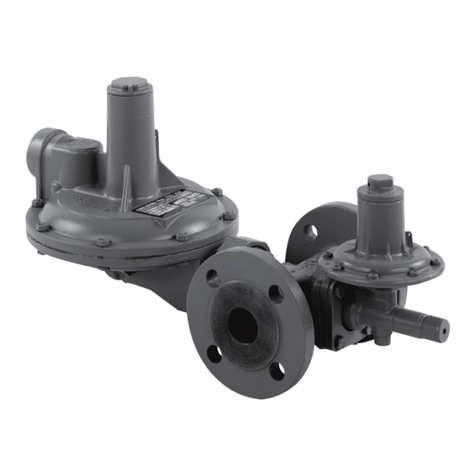
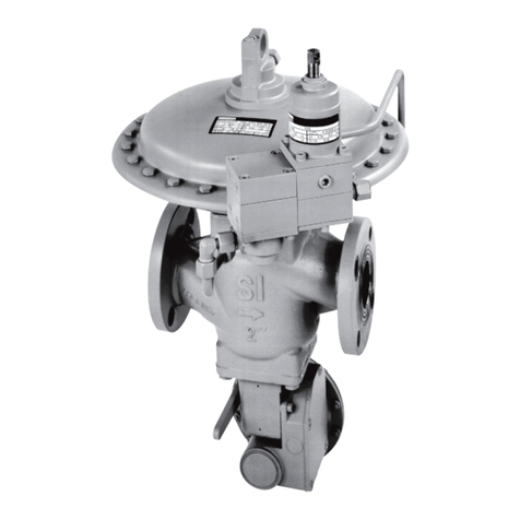
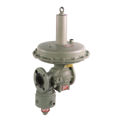
ITRON RB 4000 Instructions and recipes

RB4000 and RB1700 Regulator Installation and
Start Up
Warning Itron does not endorse or warrant the completeness or accuracy of any third party
regulator installation procedures or practices unless otherwise provided in writing by Itron.
This product, as of the date of manufacture, is designed and tested to conform to all
governmental and industry safety standards as they may apply to the manufacturer. The
purchaser/user of this product must comply with all fire control, building codes, and other safety
regulations governing the application, installation, operation, and general use of this regulator to
avoid leaking gas hazards resulting from improper installation, startup or use of this product.
Follow your company's standard operating procedures regarding the use of personal protection
equipment (PPE). Adhere to guidelines issued by your company in addition to those contained
in this document when installing or repairing natural gas regulators.
To ensure safe and efficient operation of this product, Itron strongly recommends installation by
a qualified professional.
Prior to pressure regulator installation in any piping, check to ensure that:
•The upstream and downstream flanges are parallel and the pressure regulating unit can be fitted
without undue stress.
•The upstream piping is clean of all impurities (sand, welding, slag, or other foreign materials).
•The pressure regulator is not visibly damaged.
•The inlet and outlet regulator chambers are completely clean.
After the preceding installation conditions are met, install the regulator in the piping. Ensure the gas flow
direction corresponds to the arrow on the regulator body.
Itron recommends the following safety considerations for regulator installation:
•The regulator valve body installation is in horizontal alignment.
•If the incoming or outgoing piping is constructed from ferrous material, piping contains an
electrically insulating joint upstream and downstream.
•Free passage for maintenance operations.
•In systems with an on/off gas load, the downstream volume must be greater than 1 cubic foot per
1000 cubic feet per hour of flow rate.
and regulator piping includes:
•an on/off valve upstream and downstream of the regulator.
•a manometer or pressure gauge upstream and downstream for the regulator.
•an upstream filter.
•a relief valve for accidental overpressure (for example, downstream piping exposed to direct
sunlight at zero flow).
1
Proprietary and Confidential

•To prevent negative turbulence, perform all downstream piping diameter variations progressively.
Avoid locating control line piping near direct sunlight or heat sources. You must connect the
regulator's control line to the downstream pipe. Insert control line connections in a straight section
of the downstream piping (see the installation schematics).
•To prevent impurities and condensation from collecting and obstructing gas passage, Itron
recommends welding the control line connections on the upper gas line piping.
Important Control line piping must slope slightly downwards to the pipe (see the installation
schematics.)
•To achieve the best performance from your regulator, the gas velocity at the pipe's control line
position must not exceed:
Low pressure <2.9 PSIG (50 to 65 ft/s)
Medium/high pressure >2.9 PSIG (65 to 130 ft/s)
After RB regulator installation, verify:
•The upstream and downstream on/off valves and the discharge vent pipe are closed.
•The inlet gas pressure does not exceed the established design value.
To start up the RB4000 or RB1700 regulator
1. Partially open the upstream on/off valve slowly to begin a very small gas flow.
2. Setting the shutoff valve for minimum pressure intervention causes the valve to close in the
absence of pressure. Reset the shutoff valve if it was set for minimum pressure intervention.
3. Verify the pressure rises slowly on the upstream and downstream pressure gauges.
Important The downstream pressure must stabilize around the pre-set value or a slightly higher
value. If the pressure continues to rise, interrupt the starting procedure by closing the upstream
on/off valve. Consult the trouble-shooting diagram to identify the malfunction's cause.
4. After the upstream pressure value is stabilized, open the upstream on/off valve completely.
5. Slowly open the downstream on/off valve until the piping is completely filled.
The pressure regulator is operative after you complete the start up procedure. Follow the start up
procedure when you install monitor-equipped regulators on the line with the active regulator (see the
installation schematic).
Important A pressure gauge installed in the pipe section between two regulators must
indicate the same pressure value as the upstream gauge.
Regulator Settings
The regulator is typically delivered set to the order specifications. If the set pressure must be modified, set
the value within the installed spring's setting range.
Note Verify the installed spring can achieve the desired set pressure value.
To modify regulator settings
1. To increase the set pressure value, slowly rotate the spring adjustment ferrule (lock) nut clockwise
using the adjustment wrench until the setting reaches the desired range (monitor the settings on
the downstream gauge).
2 TDC-0992-001 RB4000 and RB1700 Regulator Installation Instructions
Proprietary and Confidential

2. To decrease the set pressure value, slowly rotate the spring adjustment ferrule (lock) nut
counter-clockwise using the adjustment wrench until the setting reaches the desired range
(monitor the settings on the downstream gauge).
Important Regulator settings may be changed while the regulator is delivering flow or the
downstream on/off valve is closed. If the downstream on/off valve is closed, you must open the
discharge plug (control line intake) downstream of the regulator. Close the discharge plug after
the regulator reaches the desired setting.
Shutoff Device Settings
Note Verify the installed spring can achieve the desired set pressure value.
1. Check the shut off unit's setting.
2. To reach the maximum downstream pressure:
Close the on/off valve downstream (see the installation schematic). Slowly increase the
downstream pressure until the regulator reaches the maximum intervention pressure.
Rotate the overpressure adjustment spring nut clockwise to increase the set pressure or
counter-clockwise to decrease the set pressure.
3. To reach the minimum downstream pressure:
Close the upstream on/off valve (see the installation schematic). Slowly discharge the downstream
the downstream pressure until the regulator reaches the desired minimum intervention pressure.
Rotate the under pressure adjustment spring nut clockwise to increase the setting value. Rotate the
under pressure adjustment spring nut counter-clockwise to decrease the value.
Important Perform the shutoff valve pressure value changes with the shutoff valve diaphragm
under pressure!
Shutoff Device Reset
Note Reset the shutoff device only after you first identify the reason the shut off device
triggered.
If the valve is equipped with the minimum downstream pressure intervention function, you must reset the
shutoff valve to restore normal operating conditions.
To restore normal operating conditions
1. Close the downstream on/off valve.
2. Open the valve for the upstream and downstream pressure gauges.
3. Verify the downstream pressure = 0 (discharge any residual pressure by opening the discharge
vent pipe).
4. Close the relief and discharge valves.
5. Test the unit's valve seat seal by opening the discharge valve. Check the seal using the bubble
system test.
6. Slowly rotate the reset lever clockwise (see the installation schematic) until the internal bypass
opens.
Rotating the reset lever allows the outlet chamber, the downstream piping, and the shutoff valve
diaphragm chamber to fill. Verify pressure on the downstream gauge.
7. After the downstream pressure stabilizes, continue using the reset lever until it connects with the
control levers. At this point, the reset lever remains stable in an open position.
8. The shutoff valve is ready for service. Slowly re-open the downstream valve.
TDC-0992-001 RB4000 and RB1700 Regulator Installation Instructions 3
Proprietary and Confidential

Installation Schematics
Designator Description
1 Upstream
valve
2 Differential
Pressure gauge
3 Strainer/filter
4 Upstream
pressure gauge
5 Regulator/
monitor
6 Shutoff valve
7 Pressure gauge
8 Monitor
regulator
9 Shutoff valve
impulse
10 Regulator
impulse
11 Monitor
regulator
impulse
12 Downstream
pressure gauge
13 Discharge vent
pipe
14 Downstream
valve
15 Upstream
isolating
connection
16 Discharge
vent pipe
17 Regulator vent
18 Meter
19 Peak shaving
valve
20 Downstream
electrical
insulating
connection
4 TDC-0992-001 RB4000 and RB1700 Regulator Installation Instructions
Proprietary and Confidential
Troubleshooting
Itron is a registered trademark of Itron, Inc. © Itron, Inc. All rights reserved 30 September 2015
For technical support, contact Itron Support Services. Toll free phone: 877-487-6602
Email: s[email protected]
TDC-0992-001 RB4000 and RB1700 Regulator Installation Instructions 5
Proprietary and Confidential
Other manuals for RB 4000
2
This manual suits for next models
1
Table of contents
Other ITRON Controllers manuals