ITRON EquaScan pMIURF Owner's manual

MONTAGE- UND PROGRAMMIERANLEITUNG
EquaScan pMIURF
Impulssammler Funkmodul
LIEFERUMFANG
• Funk Impulssammlermodul
• Montageanleitung
• 5 Verbinder des Typs “Scotch Lock” für Signalkabeldurchmesser 1,52
• 1 Kunststoffplombe für den Anwender
• 1 Schraube 3,5x20 für Kabelabdeckung
ALLGEMEINES
Das EquaScan Impulssammlermodul pMIURF dient der Einbindung von impulsgebenden Verbrauchszählern in das Itron
EquaScan Funksystem für die mobile und zentrale Datenerfassung. Die Module sind jederzeit an impulsgebenden Zählern
nachrüstbar. Mit wenigen Handgriffen lässt sich das EquaScan Impulssammlermodul montieren, installieren und in den
Kreis der schon vorhandenen Funkzähler einbinden. Die induktive Schnittstelle des pMIURF dient der schnellen und fehler-
freien Parametrierung und Auslesung der Daten per PC mittels induktivem Kopf. Die Programmierung der Funkparameter
erfolgt mit der EquaScan Programmier-Software.
HINWEIS ZU LITHIUM-BATTERIEN
Das Gerät enthält nicht auswechselbare Lithium-Metall Batterien. Batterien nicht aufladen, nicht Temperaturen über 100°C
oder mechanischen Belastungen aussetzen. Es gilt Transportbestimmungen für Lithium-Batterien zu beachten.
Die für den Transport notwendigen Zertifikate können beim Hersteller angefordert werden. Setzen Sie das Gerät keinem
niedrigen Luftdruck und keiner großen Höhe aus.
RICHTIGE ENTSORGUNG / INFORMATIONEN ZUR GEEIGNETEN ENTSORGUNG VON PRODUKTEN
Das durchgestrichene Mülltonnensymbol auf dem Gerät oder auf der Verpackung weist darauf hin, dass das Altprodukt
getrennt vom Hausmüll entsorgt werden muss, damit es ordnungsgemäß behandelt und entsorgt werden kann. Erkundigen
Sie sich bei der örtlichen Behörde über den Standort von Wertstoffhöfen, um das Produkt der korrekten Wiederverwertung
zuzuführen. Der Händler muss im Fall des Kaufs eines gleichwertigen Geräts das zu recycelnde Produkt zurücknehmen.
Das Produkt ist potenziell nicht schädlich für die menschliche Gesundheit und die Umwelt, aber wenn es in der Umwelt
illegal entsorgt wird, hat es negative Auswirkungen auf das Ökosystem. Die illegale Entsorgung des Geräts in der Umwelt ist
strafbar.
Das Batteriesymbol auf dem Modul beschreibt das Ablaufdatum der Batterie.
Für den europäischen Markt.
IP68 Schutzklasse gegen Staub und Feuchtigkeit.
SCHRITTE VOR DER INSTALLATION
Prüfen Sie vor der Installation des EquaScan pMIURF, ob das Messgerät über einen Impulsausgang verfügt. Der Montageort
ist so zu wählen, dass das Modul und die Anschlussleitung nicht in der Nähe von Netzleitungen oder elektromagnetischen
Störquellen verlegt werden (min. 50 cm Abstand). Gegebenenfalls ist der Montageort neu zu wählen und die Abstände zu
vergrößern. Das Gerät in maximal 2 m Höhe anbringen. Bringen Sie das EquaScan pMIURF nicht auf heißen Wasserrohren,
in der Nähe von Wärmequellen oder an Stellen an, welche direktem Sonnenlicht ausgesetzt sind. gen Sie dafür, dass das
Modul ordnungsgemäß befestigt ist.
Übertragungsspezifikationen
Protokoll EN 13757-3/-4 wireless M-BUS
Betriebsmodus C2-Modus
Frequenzband Senden: 868,95 MHz / Empfang: 869,525 MHz

MONTAGE
Benötigtes Werkzeug: Schraubendreher, Kombizange
Das EquaScan pMIURF kann:
- mit Schrauben an einer Wand befestigt werden
- mit Montagebändern an einem Rohr befestigt werden
• Zuerst ist das Funkmodul zu konfigurieren. Befolgen Sie die untenstehenden Programmierschritte sowie die Hinweise in
dem EquaScan Software Handbuch.
• Der Abstand zwischen zwei EquaScan pMIURF muss mindestens 20 cm betragen.
• Die Kabellänge für die Verbindung vom Messgerät zum EquaScan pMIURF darf 10 m nicht überschreiten.
• Ein passendes Verlängerungskabel von 1m ist unter folgender Bestell-Nr. verfügbar: 17799
• Schließen Sie die Signalkabel des EquaScan pMIURF mittels der Verbinder des Typs « Scotch-Lock » an den Impuls-
geber an. Die Signalkabel müssen nicht abisoliert werden. Die zu verbindenden Adern in die Scotch-Lock-Verbinder
einführen und diesen mit der Kombizange zusammenquetschen und fixieren. Diese Verbindung ist nichtwieder lösbar.
Um das EquaScan pMIURF erstmalig in Betrieb zu nehmen, müssen die Adern TAMP(grün) und GND (schwarz oder braun)
verbunden werden. Bei den Itron Cyble Modulen (3wires/5wires) erfolgt diese Verbindung intern im Cyble Modul.
PROGRAMMIERUNG
Das pMIURF Modul ist ein allgemeiner Impulssammler. Zur bestimmungs-
gemäßen Verwendung muss das Modul auf den vor Ort vorhandenen Zähler-
und Impulsgebertyp programmiert werden. Hierzu wird die EquaScan-Software
verwendet. Jedes Funkmodul besitzt eine induktive Schnittstelle. Über diese
Schnittstelle wird das Modul konfiguriert. Zu jeder Zeit können, unabhängig vom
Funkbetrieb, Verbrauchs- und Geräteinformationen ausgelesen und überspielt
werden. Die induktive Schnittstelle dient zur schnellen, fehlerfreien Para-
metrierung und Auslesung der Daten per PC mittels induktivem Kopf
(Bestell-Nr.: 8090000006). Der induktive Kopf wird per USB mit dem PC
verbunden und besitzt einen Aufsatz zur Positionierung auf dem Modul.
AUSLESEN UND PROGRAMMIEREN DES MODULS
Nach der Auslesung eines Moduls über die induktive Schnittstelle steht die Eingabemaske der Modulparameter zur
Verfügung. Die durch den Administrator freigeschalteten Programmierparameter können selektiert und mit neuen Werten
überschrieben werden. Erst mit Starten des Schreibvorganges werden die eingetragenen Änderungen in das Modul über-
nommen. Weitere Modulwerte und Parameter sind über die verschiedenen Auswahlfelder auslesbar.
WARNUNG
Itron übernimmt keine Gewähr für den steten Gleichlauf zwischen impulsgebendem Zähler und pMIURF. Insbesondere bei
Verwendung von mechanischen Impulsgebern oder bei Messgeräten von Drittanbietern ist die Qualität der Impulssignale
nicht in Itron Verantwortung. Bei Abweichungen sind die Verbindungen zwischen Impulsgeber und Modul zu kontrollieren
und ein nochmaliger Abgleich vorzunehmen. Bei Wasserzählern sind ggf. Rückflussverhinderer zu montieren.
Spezifikationen
Umgebungstemperatur
im Betrieb
Zwischen 0°C und +55°C
Niedrigste Umgebungstemperatur im laufenden Betrieb: -10°C bis 5°C
(< 15 Tage/Jahr)
Höchste Umgebungstemperatur im laufenden Betrieb: 65°C (< 15 Tage/Jahr)
Lagertemperatur +5°C bis +35°C < 1 Jahr
Transporttemperatur Zwischen -20°C und 70°C < 24 Stunden durchgehend
Temperaturveränderung max. ±20°C/Stunde
Schutzart IP68
Batterielebensdauer 12 Jahre (+ 1 Jahr Reserve)
Signalparameter
Max. Eingangsspannung
Max. Eingangsstromstärke
Max. Takt-/Pulsfrequenz
Min. Takt-/Pulslänge(„Closed“)
Min. Takt-/Pulspause („Open“)
Umax = 5V
Imax = 5mA
fmax ≤ 17Hz
tcmin ≥ 6ms
tomin ≥ 50ms

• Stellen der internen Uhr.
ACHTUNG: Eine Änderung des Datums hat direkte Aus-
wirkung auf die Stichtagsfunkion!
• Einstellung des Abrechnungsmonats (Stichtagsmonat).
• Einstellung einer Kunden-Seriennummer.
• Einstellung des Messmediums.
• Einstellung des Zählerstandes.
• Aktivierung / Deaktivierung der Funk Verschlüsselung.
• Einstellung der Impulswertigkeit und der Impuls-Charakteristik.
• Ändern der Zählereinheit.
• Einstellen eines induktiven Passwortes.
• Einstellen eines Leckageschwellwertes (optional).
• Rücksetzen / Löschen von Alarmen und Registern:
- Demontage- / Manipulationsalarm
- Monatshistorie - Rückflussregister - Jahresendwerte
Eingangsbelegung der pMIURF
Kabelfarbe Kennzeichnung am Gerät Signalbeschreibung
Schwarz GND Masse (GND/Masse 0V)
Grün TAMP Manipulationskontakt & Aktivierung der pMIURF durch Verbindung mit GND
Gelb DIR/DATA Fließrichtungserkennung für Cyble 5 adrig oder als zweiter Impulsein-
gang z.B. als Wärmezähler Volumenimpulszählung nutzbar.
Rot REED VCC Impulseingang für mechanische Reed-Kontakte
Weiß OPEN COLLECTOR Impulseingang für elektronische Open-Collector Impulsgeber
Braun GND Masse (GND/Masse 0V)
MODULPARAMETER
ACHTUNG: Unabdingbar für die korrekte Funktion des Moduls ist die Programmierung des tatsächlichen Zählerstandes!
Folgende weitere Programmierparameter sind möglich:
Alle externen Schaltungen müssen nach SELV (Safety Extra Low Voltage) angelegt werden. Die Energiezufuhr ist zu be-
grenzen gemäß Kapitel 2.2 der EN 62368-1:2014 + A11:2017.
Ein- und Ausgänge sind als potentialfreie Kontakte auszulegen, die zum Schalten “trockener” Stromkreise geeignet sind.
Anschlussleitungen: Der Drahtquerschnitt beträgt AWG24 oder 0.2 mm2.
Genauere Angaben finden Sie im Benutzerhandbuch oder in der EquaScan-Software.
Zähler mit Reed Switch CF Echo Rep E/V Cyble sensors (3 wires)
GND
TAMP
DIR
REED (input 1 reed)
OPEN Collector
(input 1 statistic)
GND
GND
TAMP
DIR
REED (input 1 reed)
OPEN Collector
(input 1 statistic)
GND
GND
TAMP
DIR
REED (input 1 reed)
OPEN Collector
(input 1 statistic)
GND
GND
TAMP
DIR
REED (input 1 reed)
OPEN Collector
(input 1 statistic)
GND
GND
TAMP
DIR
REED (input 1 reed)
OPEN Collector
(input 1 statistic)
GND
GND
TAMP
DIR
REED (input 1 reed)
OPEN Collector
(input 1 statistic)
GND
Gas, Stromzähler mit P0 Interface Cyble sensor (2 wires) Cyble sensor (5 wires)
Reed Switch
GND - E / 16
REP - V / 19
TAMP
GND GND
P0 Signal
GND - Reed
GND-P0 Interf.
REP - E / 17
GND - V / 18
Out LF
Out LF Out LF
TAMP
DIR
GND

EU DECLARATION OF
CONFORMITY
DECLARATION UE DE
CONFORMITE
EG-KONFORMITÄTSERKLÄRUNG DEKLARACJA ZGODNOŚCI UE DICHIARAZIONE CE DI
CONFORMITÀ
DECLARAÇÃO CE DE
CONFORMIDADE
Number
Numéro Nummer Numery produktu Numero Numero
Name and address of the
manufacturer
Nom et adresse du fabricant
Name und Anschrift des
Herstellers
Nazwa i adres producenta
Nome ed indirizzo del
fabbricante
Nome e endereço do fabricante
This declaration of conformity is
issued under the sole responsibility
of the manufacturer.
La présente déclaration de
conformité est établie sous la seule
responsabilité du fabricant.
Die alleinige Verantwortung für die
Ausstellung dieser
Konformitätserklärung trägt der
Hersteller.
Niniejsza deklaracja zgodności
wydana zostaje na wyłączną
odpowiedzialność producenta.
La presente dichiarazione di
conformità è rilasciata sotto la
responsabilità esclusiva del
fabbricante.
A presente declaração de
conformidade é emitida sob a
exclusiva responsabilidade do
fabricante.
Object of the declaration Objet de la déclaration Gegenstand der Erklärung Przedmiot deklaracji Oggetto della dichiarazione Objecto da declaração
The object of the declaration
described above is in conformity
with the relevant Union
harmonization legislation and the
corresponding harmonized
standards
L'objet de la déclaration décrit ci-
dessus est conforme à la
législation communautaire
d'harmonisation applicable ainsi
qu'aux normes harmonisées
associées
Der oben beschriebene
Gegenstand der Erklärung erfüllt
die einschlägigen
Harmonisierungsrechtsvorschriften
der Gemeinschaft und den
entsprechenden harmonisierten
Normen
Opisany powyżej przedmiot
deklaracji jest zgodny z
odpowiednim prawodawstwem
harmonizacyjnym Unii,
podstawowymi normami
zharmonizowanymi i innymi
specyfikacjami technicznymi lub
dokumentami normatywnymi
L’oggetto della dichiarazione di cui
sopra è conforme alla pertinente
normativa comunitaria di
armonizzazione e alle
corrispondenti norme armonizzate
O objecto da declaração acima
mencionada está em conformidade
com a legislação comunitária
aplicável em matéria de
harmonização e as
correspondentes normas
harmonizadas
RED: 2014/53/EU (EU Official Journal, L 153/62, 22.05.2014), with radio option
Referenced technical
specifications:
ETSI EN 300 220-1 (V3.1.1)
RoHS: 2011/65/EU (EU Official Journal, L 174/88, 01.07.2011)
ETSI EN 300 220-2 (V3.1.1)
ETSI EN 301 489-1 (V2.1.1)
ETSI EN 301 489-3 (V2.1.1)
EN 62368-1:2014 + A11:2017
EN 62311:2008-09
Name, Function, Signature Nom, Fonction, Signature Name, Funktion, Unterschrift Imię i nazwisko, stanowisko,
podpis
Nome e cognome, Funzione,
Firma
Nome, Cargo, Assinatura
Oldenburg, 19.01.2021
Allmess GmbH
ppa. Dipl.-Ing. Dirk Glöe
Operations Manager
© Copyright 2021 Itron. All rights reserved. Document reference: 17492-AD
Place and date of issue
Date et lieu d'établissement
Ort und datum der Ausstellung
Miejsce i data wydania
Luogo e data del rilascio
Local e data da emissão
8032… (X and … = variable)
ALLMESS GmbH, Am Voßberg 11, 23758 Oldenburg i.H., GERMANY
Where applicable, certificates
issued by the notified body
Le cas échéant, certificats délivrés
par l’organisme notifié
Gegebenenfalls von der benannten
Stelle ausgestellte
Bescheinigungen
Certyfikaty wydane przez
jednostkę notyfikowaną, jeśli
dotyczy
Se del caso, certificati rilasciati
dall'organismo notificato
Se for esse o caso, certificados
emitidos pelo organismo notificado
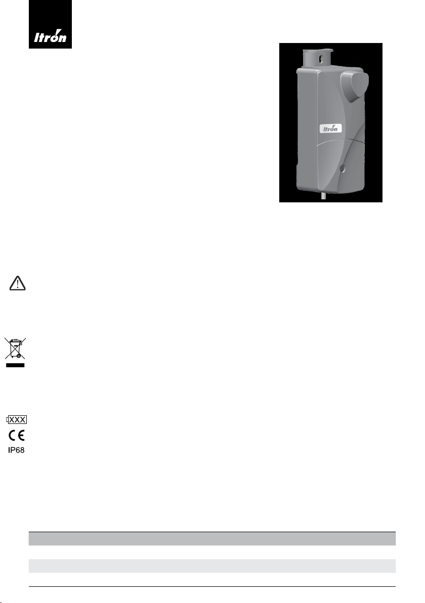
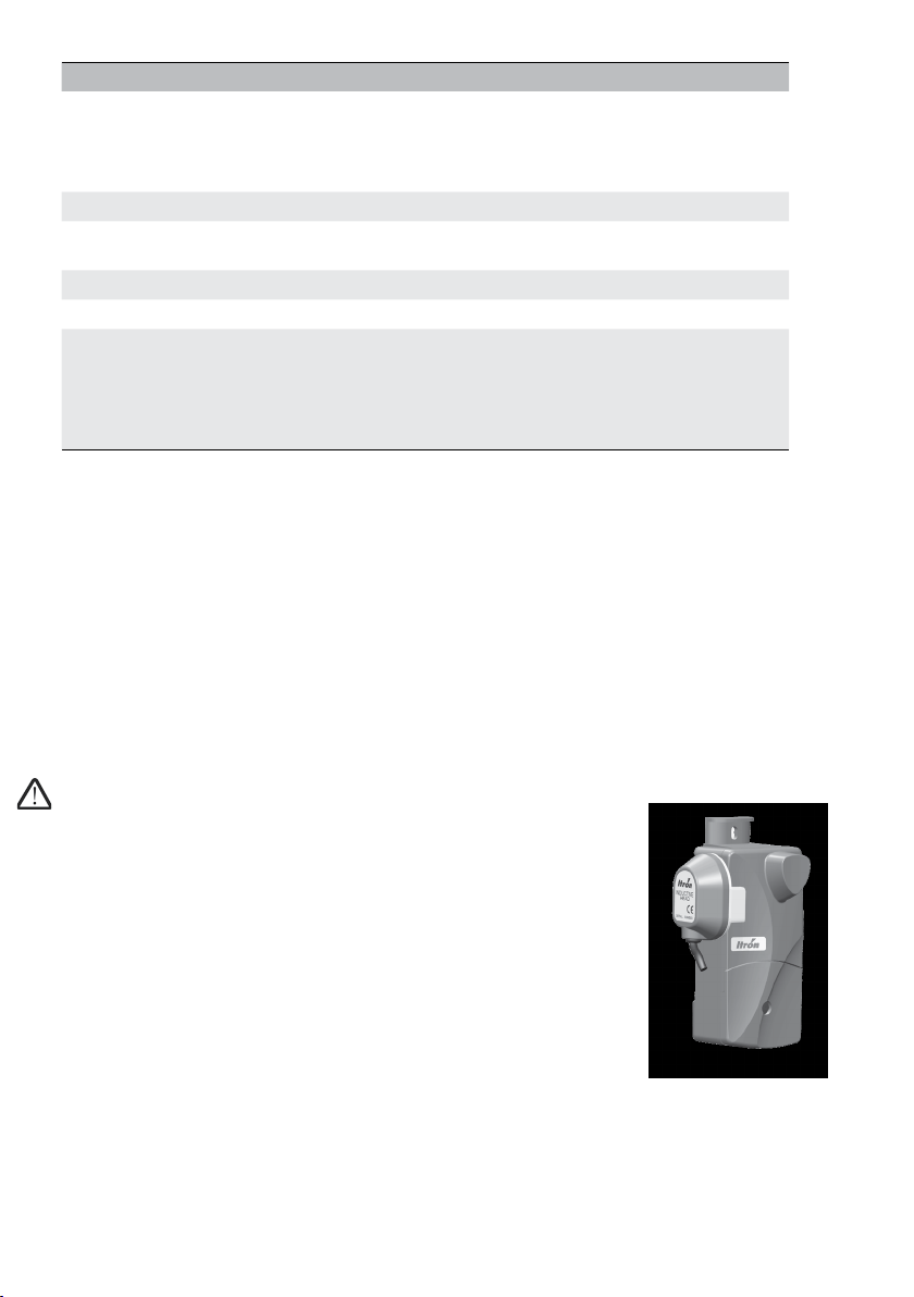
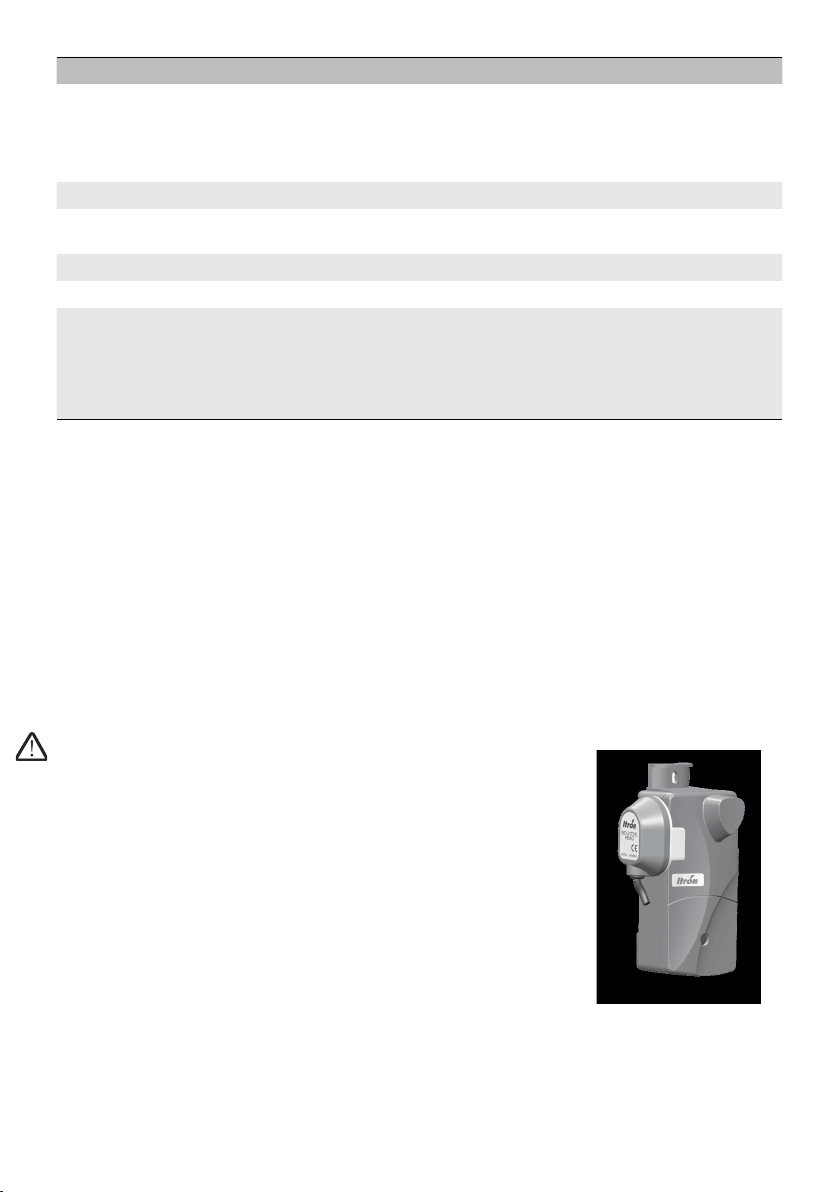
Instrument model / Instrument: EquaScan pMIU RF
Description: Radio frequency mobile data communicator
EN 61000-4-3:2006 + A1:2008 + A2:2010

ASSEMBLY AND PROGRAMMING INSTRUCTIONS
EquaScan pMIURF
Pulse Meter radio module
SCOPE OF DELIVERY
• Pulse Meter RF communication module
• Assembly instructions
• 5 “Scotch Lock” type connectors for signal cable diameter 1,52
• 1 user plastic seal
• 1 screw 3,5x20 for wire cover
GENERAL INFORMATION
The EquaScan pMIURF serves to integrate pulse emitting meters into the Itron EquaScan radio system for mobile and fixed
network data collection.
The module can be assembled, installed and integrated into the system of existing EquaScan radio meters in a few simple
steps. The EquaScan pMIURF can be programmed quickly via the computer using an Itron inductive head and the EquaScan
software.
IMPORTANT NOTIC FOR LITHIUM-BATTERIES
The device contains non-replaceable lithium metal batteries. Do not charge batteries, do not expose to temperatures
exceeding 100°C or mechanical stress. Transport regulations for lithium batteries should be considered. The certificates
required for transport can be requested from the manufacturer. Do not expose to low air pressure and high altitude.
CORRECT DISPOSAL / INFORMATION ON APPROPRIATE PRODUCT DISPOSAL
The crossed-out wheelie symbol on the equipment or on its packaging indicates that the end-of-life product must be col-
lected separately from household waste for proper treatment and recycling. Check with the local authority about the location
of appropriate ecological platforms and its subsequent correct recycling. In the case of the purchase of an equivalent device,
the distributor is required to collect the product to destroy. The product is not potentially harmful to human health and the
environment, but if it is abandoned in the environment, it has a negative impact on the ecosystem. Abandonment of the
equipment or the illegal disposal of the equipment in the environment is punishable by law.
The battery symbol on the module indicates the end year of the battery life.
For the European market.
Degree of protection against dust and water.
PRE-INSTALLATION PRECAUTIONS
Prior the installation of the EquaScan pMIURF, check if the meter is equipped with a pulse output.
Where electronic devices are to be utilized, caution should be exercised to ensure that the EquaScan pMIURF is not installed
in close proximity to power supply cables or strong electromagnetic sources such as electric motors or pumps.
Maximum installation height is limited to 2 m. Do not install the EquaScan pMIURF on hot water piping, close to any source of
heat, or exposed direct to the sunlight. Ensure that the module is properly secured.
Radio specifications
Protocol EN 13757-3/-4 wireless M-BUS
Operating mode C2 Mode
Frequency Band Tx: 868,95 MHz / Rx: 869,525 MHz

INSTALLING THE EQUASCAN pMIURF
Equipment required: screwdriver, pliers.
The EquaScan pMIURF can be:
- Screwed on the wall
- Fixed with tie-ups on a pipe
• First, the radio module shall be configurated. Please follow the programming steps described below.
• The distance between 2 EquaScan pMIURF must be 20 cm minimum.
• The cable length for the Meter connection to the EquaScan pMIURF shall be not exceed 10m.
• A fitting extension cable with 1m length can be ordered under the following order-no.: 17799
• Connect the signal wires of the EquaScan pMIURF to the pulse emitter with the « scotch-lock » type connectors.
There is no need to strip the signal wires.
• Close the cover with the metallic screw.
• Place the blue user plastic seal on the screw.
To initially start the EquaScan pMIURF the wires GND(black or brown) and TAMP(green) have to be connected. If an Itron
Cyble Sensor (3wires/5wires) is attached, this connection is ensured by the Cyble Sensor.
PROGRAMMING
To ensure the correct data transmission between the pulse emitting meter and
the EquaScan pMIURF, the meter parameter must be defined and programmed
into the module. To do this, the EquaScan software is used. Each EquaScan
pMIURF has an inductive interface, over which the module is configured. Informa-
tion on the index and device can be read and recorded over at any time, inde-
pendently of the radio operation. The inductive interface serves to quickly and
accurately parameterize and read data via the computer using an inductive head
(Order No.8090000006). See picture for positioning the inductive head.
READING AND PROGRAMMING THE MODULE
After the EquaScan pMIURF has been read via the inductive interface, the entry form for the EquaScan pulse meter RF
module parameters becomes available. The activated programming parameters can be selected and overwritten with new
values. These changes are adopted in the module when the next writing process begins. Other module values and para-
meters can be read from the various selection fields.
WARNING
The responsibility, in case of deviation between the mechanical index and the electronic index of the EquaScan pMIURF,
cannot be attributed to Itron. We invite the users to check carefully the connection between the module and the EquaScan
pMIURF. We strongly recommend to proceed with the configuration of the EquaScan pMIURF before connecting the pulse
emitting meter. We strongly recommend the installation of non-return valve or breaks to avoid the risk of reverse flow.
Characteristics
Operating ambient temperature Between 0°C and +55°C
Min. operating ambient temperature: -10°C to 5°C
(< 15 days/year)
Max. operating ambient temperature: 65°C (< 15days/year)
Storage temperature +5°C to +35°C < 1 year
Transport temperature Between -20°C and 70°C < 24 hours continuous Temperature
variation max. ±20°C/hour
Protection Class IP68
Battery lifetime 12 years (+ 1 year reserve)
Signalparameters
Max. Input Voltage
Max. Input Ampere
Max. Pulsfrequency
Min. pulse length (“Closed”)
Min- pulse pause (“Open”)
Umax = 5V
Imax = 5mA
fmax ≤ 17Hz
tcmin ≥ 6ms
tomin ≥ 50ms

• Setting the internal clock.
CAUTION: Changing the date has a direct influence on
the fixed date function!
• Setting the billing month (fixed date month).
• Setting the meter Customer serial number.
• Activating / deactivating the radio encryption.
• Setting an inductive password.
• Resetting / deleting alarms and registers:
- Removal / tamper alarm
- Monthly history
- Reverse flow register
- End-of-year indexes
You can find more precise information in the user´s
manual or the EquaScan software.
MODULE PARAMETERS
The following specific parameters related to the pulse meter are possible: Other general functional parameters from
EquaScan pulse meter RF module are possible:
All external circuits must be SELV (Safety Extra Low Voltage) and be with limited Power Source following chapter 2.2 of EN
62368-1:2014 + A11:2017. All in- and outputs should be connected on potential-free contacts suitable for dry circuits.
Connection Wires: The wire section of the individual contact is AWG24 or 0.2 mm2.
Electrical signals of the pMIURF
Wire color Marking on the Device Signal description
Black GND Ground (0V)
Green TAMP Cable cut tampering signal & pMIURF activation of RF system when con-
nected to GND (0V) of meter
Yellow DIR/DATA pMIURF pulse input : Signal for the Flow Direction/Data (logic high =
forward) or useable as a secondary pMIURF pulse input ( e.g.: CF Echo
for Rep-Volume)
Red REED VCC pMIURF pulse input : Type «Reed switch»
White OPEN COLLECTOR pMIURF pulse input : Type «Open Collector» (solid state)
Brown GND Ground (0V)
Meter w. Reed Switch CF Echo Rep E/V Cyble sensors (3 wires)
GND
TAMP
DIR
REED (input 1 reed)
OPEN Collector
(input 1 statistic)
GND
GND
TAMP
DIR
REED (input 1 reed)
OPEN Collector
(input 1 statistic)
GND
GND
TAMP
DIR
REED (input 1 reed)
OPEN Collector
(input 1 statistic)
GND
GND
TAMP
DIR
REED (input 1 reed)
OPEN Collector
(input 1 statistic)
GND
GND
TAMP
DIR
REED (input 1 reed)
OPEN Collector
(input 1 statistic)
GND
GND
TAMP
DIR
REED (input 1 reed)
OPEN Collector
(input 1 statistic)
GND
Gas, Electric Meter w. P0 Interface Cyble sensor (2 wires) Cyble sensor (5 wires)
Reed Switch
GND - E / 16
REP - V / 19
TAMP
GND GND
P0 Signal
GND - Reed
GND-P0 Interf.
REP - E / 17
GND - V / 18
Out LF
Out LF Out LF
TAMP
DIR
GND

A company certified to DIN ISO 9001 · Recognised Quality Management System to
EC Directive 2014/32/EU, Modul D · Certificate number LNE-18199
© Copyright 2022. Art-Nr. A5004219-AD · Subject to alteration · Technical status as at august 2022 · Printed on environmentally friendly paper
ITRON
ALLMESS GMBH
Am Voßberg 11
23758 Oldenburg i.H.
Germany
Tel: +49 (0) 43 61/62 5-0
Fax: +49 (0) 43 61/62 5-250
www.itron.com
Itron is a global technology company. We build solutions that help utilities
measure, manage and analyze energy and water. Our broad product port-
folio includes electricity, gas, water and thermal energy measurement and
control technology; communications systems; software; and professional
services. With thousands of employees supporting nearly 8,000 utilities
in more than 100 countries, Itron empowers utilities to responsibly and
efficiently manage energy and water resources. Join us in creating a more
resourceful world; start here: www.itron.com.
Table of contents
Languages:
Other ITRON Measuring Instrument manuals

ITRON
ITRON Aquadis+ P1 User manual

ITRON
ITRON SL7000 IEC7 User manual

ITRON
ITRON Delta Series User manual

ITRON
ITRON SHARPFLOW SWB7 User manual

ITRON
ITRON 100G User manual

ITRON
ITRON Intelis User manual

ITRON
ITRON 100W User manual

ITRON
ITRON MC3Lite Manual

ITRON
ITRON MZT User manual

ITRON
ITRON DATTUS III Installation guide

ITRON
ITRON Axonic User manual

ITRON
ITRON Centron Use and care manual

ITRON
ITRON RF1 User manual

ITRON
ITRON Bluetooth RF Master User manual

ITRON
ITRON Intelis User manual

ITRON
ITRON RF Master User manual

ITRON
ITRON Mobile Collector Lite User manual

ITRON
ITRON ACE6000 User manual

ITRON
ITRON Delta User manual

ITRON
ITRON EM512 TYPE 700 JV1 User manual