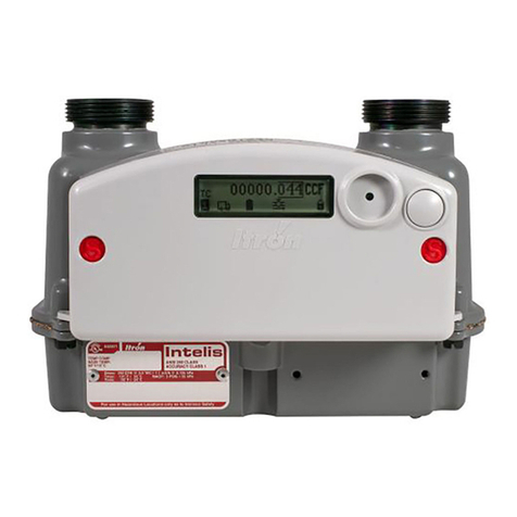
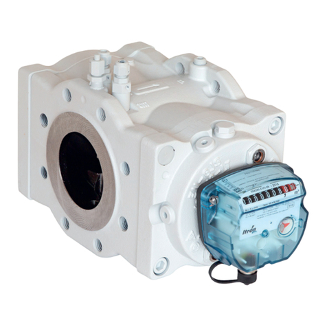
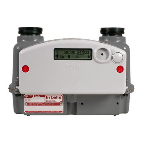
ITRON Intelis Gas Meter User manual

Intelis Gas Meter
Installation Guide
INSTALLATIONGUIDE knowledge to shape your future

Intelis Gas Meter Installation Guide
11 December 2019
TDC-1782-005
Copyright © 2019 Itron, Inc. All rights reserved.
Confidentiality Notice
Confidential Information of Itron®, Inc., provided under nondisclosure obligations. The information
contained herein is proprietary and confidential and is being provided subject to the condition that (i) it be
held in confidence except to the extent required otherwise by law and (ii) it will be used only for the
purposes described herein. Any third party that is given access to this information shall be similarly bound
in writing.
Trademark Notice
Itron is a registered trademark of Itron, Inc.
All other product names and logos in this documentation are used for identification purposes only and may
be trademarks or registered trademarks of their respective companies.
For more information about Itron or Itron products, go to www.itron.com.
If you have questions or comments about a software or hardware product, contact Itron Technical Support
Services.
Contact
Email: support@itron.com
Itron Access: https://access.itron.com
Telephone Itron Technical Support North America: 1-877-487-6602
For technical support contact information by region, go to www.itron.com and select your country and
language.
11 December 2019 TDC-1782-005 2
Intelis Gas Meter Installation Guide

Table of Contents
In telisGa s Me terInstallatio n Gu ide 1
Ta b leo fCon tents 3
1 Important Safety and Compliance Information 5
USA, FCC Part 15 Spectrum Compliance 5
USA, FCC Class B-Part 15 5
Modifications and Repairs 5
Canada, ISED Spectrum Compliance 6
RF Exposure (FCC/ISED) 6
Australia, ACMA Spectrum Compliance 6
Electromagnetic Compatibility 7
Intrinsic Safety 7
Lithium Battery 7
Transportation Classification 7
Electrostatic Discharge 7
Electrostatic Ignition Hazard 8
Device Cleaning 8
Do Not Drop 8
Product Notification 8
2 Intelis Gas Meter 10
Related Documents 10
Models 11
Components 11
Internal Safety Shutoff Valve 12
Integrated RF Communications Module 12
Specifications 12
Dimensions 14
3 Installation 16
Prior to Start-Up 17
Start-Up 17
Removing or Installing the Pipe Plug 18
Removing 18
11 December 2019 TDC-1782-005 3

Installing 18
4 LCD Operation 20
Intelis Gas Meter LCD 20
LCD Display Alarms 22
Additional LCD Screen Displays 25
LCD Display Icons 26
Performing an LCD Test 27
5 Proving 28
Test Mode 29
Entering Test Mode 29
Recording Test Mode Consumption 30
Exiting Test Mode 30
Prover Types 30
Proving the Intelis Gas Meter Using the Honeywell SNAP Proving System 31
Proving the Intelis Gas Meter Using the Measurement Systems Proving System 41
Proving the Intelis Gas Meter Using the Energy Economics (EEI) Proving System 58
6 Adjusting the Calibration 67
To Adjust the Calibration of an Intelis Gas Meter 67
To Seal an Intelis Gas Meter 74
To Unseal an Intelis gas Meter's UMU 76
7 Maintenance 78
11 December 2019 TDC-1782-005 4
Intelis Gas Meter Installation Guide Table of Contents

1
Important Safety and Compliance Information
This section provides important information for your safety and product compliance.
USA, FCC Part 15 Spectrum Compliance
This device complies with Part 15 of the FCC Rules. These limits are designed to provide reas-
onable protection against harmful interference in a residential installation.
Operation is subject to the following two conditions:
■This device may not cause harmful interference.
■This device must accept any interference that may cause undesirable operation.
This device must be installed to provide a separation distance of at least 20 centimeters (7.9
inches) from all persons to be compliant with regulatory RF exposure.
USA, FCC Class B-Part 15
This equipment has been tested and found to comply with the limits for a Class B digital device,
pursuant to Part 15 of the FCC Rules. These limits are designed to provide reasonable pro-
tection against harmful interference in a residential installation. This equipment generates, uses,
and can radiate radio frequency energy and, if not installed and used in accordance with the
instructions, may cause harmful interference to radio communications. However, there is no
guarantee that interference will not occur in a particular installation. If this equipment does cause
harmful interference to radio or television reception, which can be determined by turning the
equipment off and on, the user is encouraged to try to correct the interference by one or more of
the following measures:
■Reorient or relocate the receiving antenna.
■Increase the separation between the equipment and receiver.
■Connect the equipment into an outlet on a circuit different from that to which the receiver is
connected.
■Consult the dealer or an experienced radio or TV technician for help.
Modifications and Repairs
To ensure system performance, this device and antenna shall not be changed or modified
without the express approval of Itron. Per FCC rules, unapproved modifications or operation bey-
ond or in conflict with these instructions for use could void the user's authority to operate the
equipment.
11 December 2019 TDC-1782-005 5

Canada, ISED Spectrum Compliance
Compliance Statement Canada Déclaration de Conformité
This device complies with Innovation, Science
and Economic Development Canada (ISED)
license-exempt RSS standard(s). Operation is
subject to the following two conditions: (1) this
device may not cause interference, (2) this device
must accept any interference, including inter-
ference that may cause undesired operation of
the device.
Under Innovation, Science and Economic Devel-
opment Canada (ISED) regulations, this radio
transmitter may only operate using an antenna of
a type and maximum (or lesser) gain approved for
the transmitter by Industry Canada. To reduce
potential radio interference to other users, the
antenna type and its gain should be so chosen
that the equivalent isotropically radiated power
(e.i.r.p.) is not more than that necessary for suc-
cessful communication.
Le présent appareil est conforme aux CNR
d'Industrie Canada applicables aux appareils
radio exempts de licence. L'exploitation est autor-
isée aux deux conditions suivantes: (1) l'appareil
ne doit pas produire de brouillage, (2) l'utilisateur
de l'appareil doit accepter tout brouillage radi-
oélectrique subi, même si le brouillage est sus-
ceptible d'en compromettre le fonctionnement.
Conformément à la réglementation d'Industrie
Canada, le présent émetteur radio peut fonc-
tionner avec une antenne d'un type et d'un gain
maximal (ou inférieur) approuvé pour l'émetteur
par Industrie Canada. Dans le but de réduire les
risques de brouillage radioélectrique à l'intention
des autres utilisateurs, il faut choisir le type
d'antenne et son gain de sorte que la puissance
isotrope rayonnée équivalente (p.i.r.e.) ne
dépasse pas l'intensité nécessaire à
l'établissement d'une communication sat-
isfaisante.
RF Exposure (FCC/ISED)
This equipment complies with radiation exposure
limits set forth for an uncontrolled environment.
This equipment should be installed and operated
with minimum distance 20 cm between the radi-
ator and your body. This transmitter must not be
co-located or operating in conjunction with any
other antenna or transmitter.
Cet équipement est conforme aux limites
d'exposition aux radiations dans un environnement
non contrôlé. Cet équipement do it être installé et
utilisé à distance minimum de 20 cm entre le radi-
ateur et votre corps. Cet émetteur ne doit pas être
co-localisées ou opérant en conjonction avec tout
autre antenne ou transmetteur.
Australia, ACMA Spectrum Compliance
When this device is sold and shipped to Australia, it is configured and labeled accordingly to be
compliant with ACMA Standards for the Radio, EMC and RF Exposure. This includes standard
AS/NZS 4268 RF spectrum standard for frequency and power out.
11 December 2019 TDC-1782-005 6
Intelis Gas Meter Installation Guide 1 Important Safety and Compliance Information
Electromagnetic Compatibility
Warning! Use only approved accessories with this equipment. All cables must be
high quality, shielded, and correctly terminated. Unapproved modifications or oper-
ation beyond or in conflict with these use instructions may void the authority's author-
ization to operate the equipment.
Intrinsic Safety
Warning! Substitution of components may impair intrinsic safety.
Lithium Battery
Warning! Follow these procedures to avoid injury to yourself or others.
■The lithium battery may cause a fire or chemical burn if it is not disposed of properly.
■Do not recharge, disassemble, heat above 212°Fahrenheit (100°C Celsius), crush, expose
to water, or incinerate the lithium battery. Fire, explosion, and severe burn hazard.
■The battery used in this device may present a risk of fire or chemical burn if mistreated.
■Keep the lithium battery away from children.
Transportation Classification
The Federal Aviation Administration prohibits operating transmitters and receivers on all com-
mercial aircraft. When powered and not in Factory ship mode, the Itron device is considered an
operating transmitter and receiver and cannot be shipped by air. All product returns must be
shipped by ground transportation.
Electrostatic Discharge
Warning! Internal circuit components can be sensitive to electrostatic discharge.
Before installation, discharge electrostatic buildup by touching a metal pipe or other
earth-grounded metal object prior to touching the meter body, register housing, or
Itron device.
11 December 2019 TDC-1782-005 7
Intelis Gas Meter Installation Guide 1 Important Safety and Compliance Information
Electrostatic Ignition Hazard
Warning! Verify the area is not hazardous when installing, servicing, cleaning, or
touching the Itron device.
Device Cleaning
Warning! Clean only with a damp cloth.
Do Not Drop
Warning! While Itron meters are designed to withstand a drop, dropping the meter
may damage the device, impact the meter accuracy, and void the warranty.
Product Notification
These instructions are not intended to replace any utility or company-established meter install-
ation procedures. These instructions are provided for additional information when the Intelis Gas
Meter is installed. The meter installation must comply with all country, state, and local building
and safety regulations as well as federal regulations including Section 192.353 of Title 49 of the
Code of Federal Regulations. Two pertinent paragraphs of the code are:
■Each meter and service regulator, whether inside or outside of a building must be in a readily
accessible location and be protected from corrosion and other damage.
■Each meter installed within a building must be located in a ventilated place and not less than
3 feet from any source of ignition or any source of heat which might damage the meter.
The Intelis Gas Meter is rated for the following operating and storage temperature ranges. Use
of the meter outside of the listed temperature ranges is not recommended.
■Operating ranges:
–Measurement -30° F (-34° C) to +131° F (55° C)
–Valve -13° F (-25° C) to +131° F (55° C)
–RF -40° F (-40° C) to +158° F (70° C)
■Storage range:
–-40° F (-40° C) to +158° F (70° C)
■Direct inquiries as to the selection and application of gas meters to your local Itron sales rep-
resentative or Itron Support.
11 December 2019 TDC-1782-005 8
Intelis Gas Meter Installation Guide 1 Important Safety and Compliance Information
■Itron does not endorse or warrant the completeness or accuracy of any third-party meter
installation procedures or practices, unless otherwise provided in writing by Itron.
–Follow your company's standard operating procedures regarding the use of personal pro-
tection equipment (PPE).
–Adhere to guidelines issued by your company in addition to those given in this document
when installing or repairing meters.
11 December 2019 TDC-1782-005 9
Intelis Gas Meter Installation Guide 1 Important Safety and Compliance Information
2
Intelis Gas Meter
The Intelis Gas Meter is a solid state ultrasonic meter featuring an internal safety shut-off valve,
built-in temperature conversion, and an integrated RF communications module. The meter sup-
ports the listed functionality.
■High flow alarm with optional automatic valve shutoff.
■High temperature alarm with an optional automatic valve shutoff.
■Air detection.
■Reverse flow detection.
The Intelis Gas Meter can be configured for Mobile Mode or OpenWay Riva Network Mode. This
compact meter weighs only 4-1/2 pounds and mounts well within existing meter footprints for
easy meter installation and replacement of existing gas meters.
Related Documents
For more information about the Intelis Gas Meter and compatible system architecture doc-
umentation, see your product's documentation.
11 December 2019 TDC-1782-005 10

Document Itron part number
Intelis Gas Meter Technical Reference Guide TDC-1805-XXX
Intelis Gas Meter Ordering Guide PUB-1309-000
Intelis Gas Meter Specification Sheet 101584-SP-XX
Intrinsic Safety Control Drawing Index Module Replacement Intelis Gas
Meter
TDC-0978-009
Intelis Gas Meter Battery Replacement Instructions TDC-0978-011
OpenWay® Operations Center Collection Manager Device Interface Guide TDC-7083-XXX
Itron Security Manager User Guide TDC-1380-XXX
Field Deployment Manager Tools Configuration Guide TDC-1711-XXX
Field Deployment Manager Tools Application Guide TDC-1713-XXX
Field Deployment Manager Field Representative's Guide TDC-1714-XXX
Models
The Intelis Gas Meter is available in the following types:
■Temperature compensated
■Non-temperature compensated
Components
The Intelis Gas Meter features the following components in a compact solid state meter:
■Intelis Gas Meter index
–The index contains the integrated RF communications module, battery pack, and the
liquid crystal display (LCD). The LCD provides a visual display of consumption, alarm
messages, and status information. For information about LCD operation, see Intelis
Gas Meter LCD.
■An internal shutoff valve
■Ultrasonic measuring unit (UMU)
■Inlet and outlet tube
■Dust trap and filter
■Die cast aluminum case
■Steel hubs
11 December 2019 TDC-1782-005 11
Intelis Gas Meter Installation Guide 2 Intelis Gas Meter

Internal Safety Shutoff Valve
Caution: It is mandatory that a technician be on site at the meter to re-open the valve
and ensure safe conditions before the flow of gas is resumed after a valve has been
closed.
The Intelis Gas Meter shutoff valve is located in the outlet of the meter. The automatic shutoff
valve is a safety feature automatically triggered if the meter is configured for automatic shut off
for high flow or high temperature events. The valve can also be shut off through an RF command
over the Mobile or OpenWay Riva Network.
Automatic Shutoff Configuration
The Intelis Gas Meter can be configured for an automatic shut off for the following event types.
■High flow. Configuration for a high flow event enables an automatic shut off if the high flow
threshold is reached or exceeded in a configurable window of time.
■High temperature. Configuration for a high temperature event enables an automatic shut
off if the high temperature threshold is reached or exceeded.
For more information about high flow and high temperature event configuration, see the FDM
documentation. For document information, see Related Documents.
Integrated RF Communications Module
The integrated RF communications module is designed to operate in either Mobile or OpenWay
Riva Network Mode. When the Intelis Gas Meter is operating in Mobile Mode, it may be read by
ChoiceConnect handheld readers, mobile collection, or the Itron Mobile Radio connected to a
user-supplied computer or Bluetooth device. When the meter is operating in OpenWay Riva Net-
work Mode, it is read by the OpenWay Riva Network. For compatible Itron reading and pro-
gramming devices, see the Intelis Gas Meter Technical Reference Guide (TDC-1805-XXX).
Note: The communication functionality is dependent on the module's firmware version.
Specifications
The following table lists the Intelis Gas Meter product specifications.
Specification Specification value
Meter capacity 250 CFH at ½ w.c. / 7.1 m3/h @0.125 kPa
Measurement principle Ultrasonic time of flight
Table 1Intelis Gas Meter specifications
11 December 2019 TDC-1782-005 12
Intelis Gas Meter Installation Guide 2 Intelis Gas Meter

Specification Specification value
Accuracy Class 1 and ±0.5% at room temperature
Meter type Temperature compensated (TC) or non-temperature compensated (NTC)
Hub center-to-center 6 inches (152.4 mm)
Hub size options ■10LT
■20LT
■30LT
■1A/Sprague standard
■1-1/4", 1" Pittsburgh
■ISO G 1-1/4"
Meter MAOP 5 PSIG (35 kPa)
Valve Actuated swing valve, maximum 0.035 CFH (1 L/H) leakage rate
LCD displayed units CCF (100 x cubic foot) or cubic meter
LCD resolution 00000.001 CCF (0.1 CF) or 00000.001 m3
Case Aluminum case with ASA 49 gray powder coat finish
Weight 4.5 lbs (2.0 kg)
Gas type Natural gas Type H, E, L (per EN 437)
Reference gases G20, G21, G23, G25, G26, G27
Component materials ■UMU (ultrasonic measuring unit): polybutylene terephthalate (PBT) and polycar-
bonate (PC)
■Valve plastics: PBT
■Inlet and outlet tubes: polyoxymenthylene (POM)
Intrinsically safe For use in Class I, Division 1, Group D hazardous locations. Temp Code T1 -40°C
≤ Ta ≤ +70°C
IECEx UL 18.0144X Ex ia IIA T1 Ga
Regulatory FCC: Part 15.247, Part 15.249 (programming)
FCC ID: EWQINTELISG
Innovation, Science, and Economic Development Canada (ISED): RSS-247 and
RSS-210 (programming)
IC ID: 864D-INTELISG
Measurement Canada: Pending
Table 1Intelis Gas Meter specifications (continued)
11 December 2019 TDC-1782-005 13
Intelis Gas Meter Installation Guide 2 Intelis Gas Meter

Specification Specification value
Operational All Intelis Gas Meters operate without the need for an FCC or ISED license
Frequency: 902-928 MHz ISM band
Program frequency: 908-923.8 MHz
Australia ACMA AS/NZS 4268
Frequency: 915-928 MHz ISM band
Program frequency: 916-926.8 MHz
Operating temperature rat-
ings
Measurement -30° F (-34° C) to +131° F (55° C)
Valve -13° F (-25° C) to +131° F (55° C)
RF -40° F (-40° C) to +158° F (70° C)
Storage temperature ratings -40° F (-40° C) to +158° F (70° C)
Battery information 4 Lithium manganese dioxide (LiMnO2) 'A' cell batteries, replaceable
Battery life 20 years for meter, RF, and valve using recommended operating parameters
Pressure tap 1/8" NPT pipe plug pressure tap standard on meter outlet
Badging Standard aluminum manufacturing and optional customer badge
Test pulse weight (volume
per pulse)
0.10CF, 0.25CF, 0.50CF, 1.0CF, 10dm3, 50dm3
Test pulse width 10 ms - 1000 ms (1 second)
Minimum compatible col-
lection software for Mobile
FCS v4.1
FDM Tools v4.2
ISM v3.6 (if using enhanced security)
Itron Mobile v1.5
Mobile Collection v3.8.2
Standards Designed in compliance with ANSI B109.1, ANSIB109.0 (draft), and Measurement
Canada PS-G-06
Table 1Intelis Gas Meter specifications (continued)
Dimensions
This section lists the Intelis Gas Meter dimensions. Dimensions are listed in Imperial and Metric
units.
11 December 2019 TDC-1782-005 14
Intelis Gas Meter Installation Guide 2 Intelis Gas Meter

A B C D E F G
8.4 inches 6.4 inches 6.0 inches 5.4 inches 3.1 inches 9.1 inches 1.9 inches
214.4 mm 161.9 mm 152.4 mm 138.3 mm 78.6 mm 230.6 mm 48.8 mm
Table 2Intelis Gas Meter dimensions
Note: B dimension can vary with different hubs options. (20LT is shown).
11 December 2019 TDC-1782-005 15
Intelis Gas Meter Installation Guide 2 Intelis Gas Meter

3
Installation
This section provides the Intelis Gas Meter installation information.
Warning! This product, as of the date of its manufacture, is designed and tested to
conform to all governmental or industry safety standards then existing as they may
apply to the manufacturer. The purchaser and user of this product are warned that
compliance with all country, state, and local codes required in order to avoid the haz-
ards of leaking gas resulting from improper installation, start-up, or use of this product,
and further, that all fire control, building codes, or other safety regulations established
under public laws which regulate or govern the application, installation, operation, or
general use of this product, should be complied with. In order to ensure the safe and
proper operation of this product, the manufacturer recommends that a qualified tech-
nician install this product.
The Intelis Gas Meter must be installed with the inlet to the left, the outlet to the right, the meter in
a horizontal position and with the LCD facing out. INLET and a flow arrow are marked on the
Intelis Gas Meter casing.
Note: These instructions assume the gas is turned off, the previous gas meter is removed
(when the Intelis Gas Meter is replacing an existing installation), piping tests are completed,
and all safety requirements are met.
11 December 2019 TDC-1782-005 16

Prior to Start-Up
Note: The Intelis Gas Meter is shipped from the factory with the shutoff valve in the open pos-
ition. Verify the valve is open prior to installing the meter. Confirm the open valve icon is dis-
played on the LCD display and that the valve closed icon is not displaying.
Perform a visual check of the inside of the meter outlet to also verify the shutoff valve is open.
Before the Intelis Gas Meter start-up:
■Read the meter badge data regarding maximum allowable operating pressure (MAOP) and
capacity flow rate to be sure the meter meets the installation requirements.
■Sight across both swivel flanges or test with a suitable level to determine that the flanges are
nominally in the same plane and will not cause excessive strain on the meter or piping when
the connection nuts are tightened.
Start-Up
1. Blow out the service lines before the meter is installed to ensure no dirt, debris, or liquids of
any kind will be carried into the meter when the gas is flowing in the line.
2. Place a new connection nut washer (gasket) on each connect nut or meter hub.
3. Support the meter so that both hubs are against the connection washers and run the con-
nection nuts down hand tight.
4. In an alternating fashion, tighten the nuts to the appropriate torque for the connection size.
5. Check the meter's downstream system to ensure that all connections are leak free or that
the downstream valve, if one is present, is closed.
6. Open the upstream and downstream valves very slowly to prevent any pressure surges into
or out of the meter.
11 December 2019 TDC-1782-005 17
Intelis Gas Meter Installation Guide 3 Installation

Caution: Avoid high differential pressure across the meter. Abnormal differential
pressures can damage internal meter components.
7. Alternate cracking open the upstream and downstream valves for a few seconds and then
slowly-over a period of 10 seconds (¼ PSIG systems)-turn the valve to the ¼ open position
and then to the full open position.
8. After the meter is pressurized, apply a soap solution or other good leak detecting liquid to the
connections to check for leaks.
9. Test the meter to verify the meter is registering the gas flow.
1. Press the button to activate the LCD.
2. Observe the LCD display and look for usage to increase.
Note: If the LCD does not display any expected consumption, investigate the install-
ation. If necessary, change out the meter.
10. Perform a shadow or lock-in test following company or utility procedures.
11. After the Intelis Gas Meter installation testing is complete, purge all air from the gas line
including the piping section.
Warning! Never allow gas to discharge into a confined space or area where
there are ignition sources unless precautions are in place to eliminate potential
hazardous conditions.
It is possible to get air detection alarms during Intelis Gas Meter installation due to installation
setups, gas pressure, flow rates, pipe length, and general installation practices. Air detection
alarms during installation should be ignored.
Removing or Installing the Pipe Plug
This section provides the steps to remove or re-install the pipe plug.
Removing
Using a 3/16" hand-driven Allen wrench, remove the pipe plug.
Installing
1. Clean any debris from the pipe plug and inspect it for any damage or deformation. Replace
the pipe plug if any defects or wear are found.
11 December 2019 TDC-1782-005 18
Intelis Gas Meter Installation Guide 3 Installation

2. Apply new sealant to the leading 3 to 4 threads of the pipe plug.
Note: Itron recommends RectorSeal #5 sealant.
3. Using a 3/16" hand-driven Allen wrench, begin tightening the pipe plug into the threads,
using care not to cross-thread or remove the sealant during the process.
4. Tighten the pipe plug. Do not exceed 50 inch-pounds torque (5.6 Newton Meters).
5. Leak test following your utility's leak test procedure.
11 December 2019 TDC-1782-005 19
Intelis Gas Meter Installation Guide 3 Installation

4
LCD Operation
This section provides information about the Intelis Gas Meter LCD.
Intelis Gas Meter LCD
This section describes the Intelis Gas Meter LCD menus that are displayed in a pre-defined
order (1-8).
Note: The Intelis Gas Meter ships in a sealed (locked) state.
Additionally, there are two screens that display in response to an overflow or test condition.
Note: The two additional menu pages provide overflow condition information and an inter-
face to perform an LCD test.
The LCD test is initiated by a long press. These additional menu pages are not a part of the nor-
mal sequence. The LCD normal mode is off. A button press will activate the LCD. Each menu
page is active for 6 seconds before the LCD advances to the next menu page. When the last
menu page is reached, the process loops to the first menu page until the configured timeout is
reached.
Note: A button press will also advance the LCD to the next menu page.
11 December 2019 TDC-1782-005 20
Table of contents
Other ITRON Measuring Instrument manuals

ITRON
ITRON Delta Series User manual

ITRON
ITRON MZT User manual

ITRON
ITRON CENTRON CP1S Use and care manual

ITRON
ITRON SL7000 IEC7 User manual

ITRON
ITRON EquaScan pMIURF Owner's manual

ITRON
ITRON CENTRON C1SR Use and care manual

ITRON
ITRON SHARPFLOW SWB7 User manual

ITRON
ITRON MC3Lite Manual

ITRON
ITRON DN15 User manual

ITRON
ITRON ACE6000 User manual

ITRON
ITRON Delta User manual

ITRON
ITRON G16 User manual

ITRON
ITRON Centron Use and care manual

ITRON
ITRON 100W User manual

ITRON
ITRON OpenWay Intelis User manual

ITRON
ITRON CCU 100 User manual

ITRON
ITRON Axonic User manual

ITRON
ITRON DATTUS III Installation guide

ITRON
ITRON G10 User manual

ITRON
ITRON Bluetooth RF Master User manual