IXXAT CAN@net II User manual

The expert for industrial and automotive communication
Manual
CAN@net II
Intelligent PC/CAN Interface

IXXAT
Headquarter US Sales Office
IXXAT Automation GmbH IXXAT Inc.
Leibnizstr. 15 120 Bedford Center Road
D-88250 Weingarten USA-Bedford, NH 03110
Tel.: +49 (0)7 51 / 5 61 46-0 Phone: +1-603-471-0800
Fax: +49 (0)7 51 / 5 61 46-29 Fax: +1-603-471-0880
Internet: www.ixxat.de Internet: www.ixxat.com
e-Mail: [email protected] e-Mail: [email protected]
Support
In case of unsolvable problems with this product or other IXXAT products
please contact IXXAT in written form by:
Fax: +49 (0)7 51 / 5 61 46-29
e-Mail: [email protected]
For customers from the USA/Canada
Fax: +1-603-471-0880
e-Mail: [email protected]
Copyright
Duplication (copying, printing, microfilm or other forms) and the electronic
distribution of this document is only allowed with explicit permission of
IXXAT Automation GmbH. IXXAT Automation GmbH reserves the right to
change technical data without prior announcement. The general business
conditions and the regulations of the license agreement do apply. All rights
are reserved.
Document number: 4.01.0086.20000
Version: 1.4

Copyright IXXAT Automation GmbH CAN@net II - Manual, V1.4
Contents
3
1Introduction ..............................................................................5
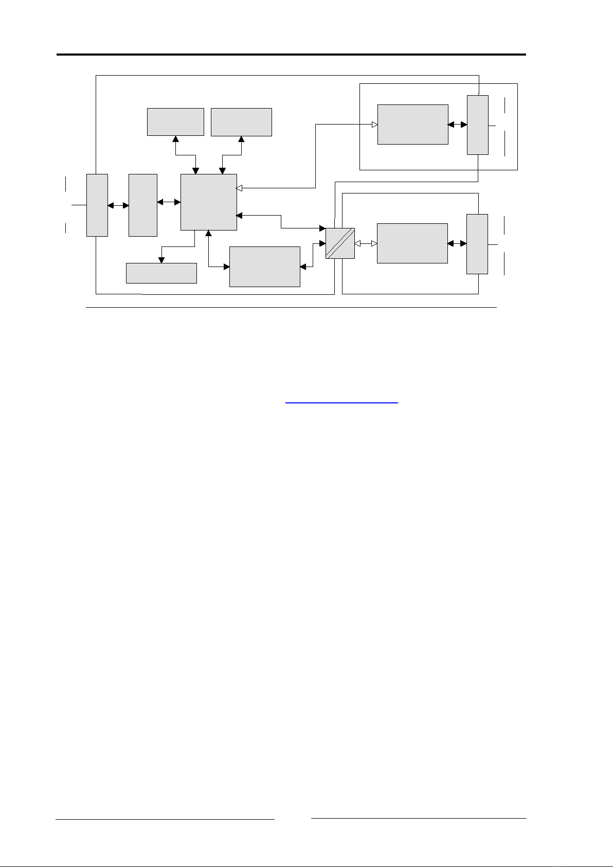
1.1 Overview .............................................................................5
1.2 Features ..............................................................................5
1.3 Support...............................................................................6
1.4 Returning hardware............................................................6
2Installation.................................................................................7
2.1 Software installation ..........................................................7
2.2 Hardware installation .........................................................7
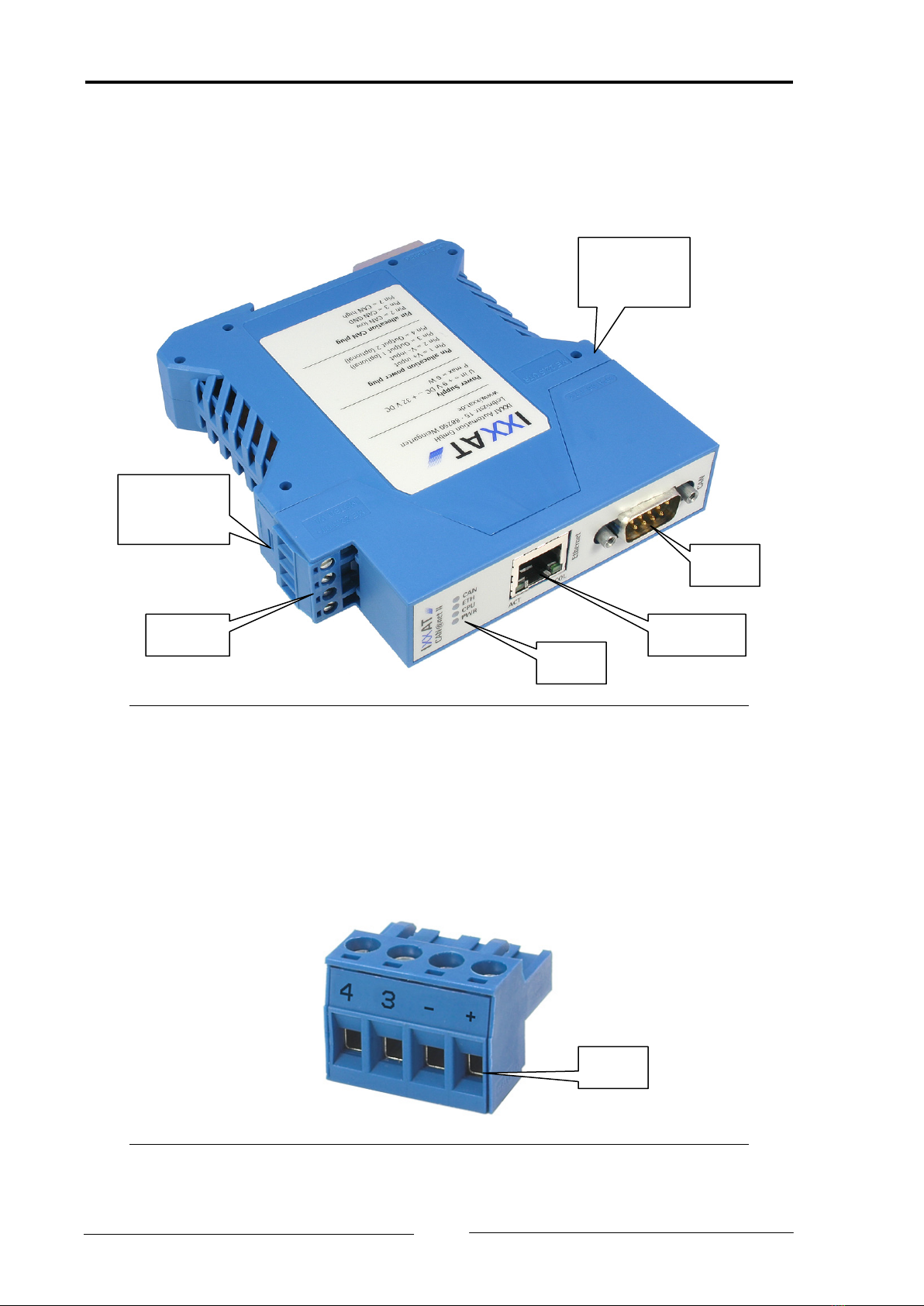
3Connections and indicators.......................................................8
3.1 Pin allocation ......................................................................8
3.1.1 Power connector ....................................................................... 8
3.1.2 Ethernet socket.......................................................................... 9
3.1.3 CAN bus connector ................................................................. 10
3.2 Indicators..........................................................................10
3.2.1 Power LED (PWR)..................................................................... 11
3.2.2 Status LED (CPU)...................................................................... 11
3.2.3 Ethernet LED (ETH) .................................................................. 12
3.2.4 Collision LED (COL) .................................................................. 12
3.2.5 Link/Data Activity LED (ACT)..................................................... 13
3.2.6 CAN LED (CAN)........................................................................ 13
3.3 CAN bus termination ........................................................14
4Configuration ..........................................................................14
4.1 Configuration Tool ............................................................14
4.1.1 Overview ................................................................................. 14
4.1.2 Usage...................................................................................... 15
4.2 Resetting the network parameters ...................................15
5Appendix .................................................................................17
5.1 Technical specifications.....................................................17
5.2 Default Network Settings .................................................18
5.3 Accessories........................................................................18
5.3.1 CAN bus termination resistor ................................................... 18
5.4 Notes on EMC ...................................................................19
Declaration of conformity .......................................................20
FCC Compliance.......................................................................21


Copyright IXXAT Automation GmbH CAN@net II - Manual, V1.4
Introduction
5
1Introduction
1.1 Overview
Congratulations on your purchase of the IXXAT PC/CAN interface CAN@net II, a
high-quality electronic component developed and manufactured according to the
latest technological standards.
This manual is intended to familiarize you with the device. Please read this manu-
al before beginning with the installation.
For miscellaneous applications IXXAT offers different versions of the CAN@net II.
As a TCP/IP based PC/CAN interface for standard Windows applications the
CAN@net II/VCI is the best choice. It offers with the IXXAT standard Windows
driver interface VCI an easy to handle and wide functional interface for Windows
applications. The IXXAT tools also use this standard driver interface.
The CAN@net II/Generic offers with a generic ASCII interface via TCP/IP the pos-
sibility to use the device in non-Windows systems such as Linux operating sys-
tems. Additionally, two CAN@net II/Generic devices can be used as a bridge. This
makes it possible to connect two CAN networks which are far away from each
other via TCP/IP. The CAN@net II/Generic devices receive the CAN messages of
their CAN network and transmit them via TCP/IP to the other CAN@net II/Generic
device. Filters can be set on configuration of the bridge, so only messages which
are interesting for the other network are exchanged.
For the different CAN@net II versions, specific manuals are available. This manual
describes the software installation and the programming and integration of the
devices into customer applications.
1.2 Features
•power supply range +9 V - +32 V DC
•Freescale 32 Bit microcontroller with 150 MHz clock
•8 MByte DRAM
•4 MByte flash
•1 CAN-Controller PHILIPS SJA1000 with 16 MHz clock
•CAN bus interface according to ISO 11898-2, galvanically isolated
•Ethernet PHY with Auto Crossover
•10BASE-T/100BASE-TX Ethernet

Copyright IXXAT Automation GmbH CAN@net II - Manual, V1.4
Introduction
6
MC-Potential
MC
MCF5235
150MHz
DRAM
(8 MB)
CAN-Controller
SJA1000
Flash
(4 MB)
LEDs
Ethernet
PHY
Ethernet
Ethernet
CAN-Potential
High-Speed
SN65HVD251
CAN
CAN
High-Speed
SN65HVD231
CAN
CAN
optional
Picture 1-1: Block diagram of the CAN@net II
1.3 Support
For more information on our products, FAQ lists and installation tips, please refer
to the support section of our website (http://www.ixxat.de), which also contains
information on current product versions and available updates.
If you have any further questions after studying the information on our website
and the manuals, please contact our support department. The support section on
our website contains the relevant forms for your support request. In order to fa-
cilitate our support work and enable a fast response, please provide precise in-
formation on the individual points and describe your question or problem in de-
tail.
If you would prefer to contact our support department by phone, please also
send a support request via our website first, so that our support department has
the relevant information available.
1.4 Returning hardware
If it is necessary to return hardware to us, please download the relevant RMA
form from our homepage and follow the instructions on this form. In the case of
repairs, please also describe the problem or fault in detail on the RMA form. This
will enable us to carry out the repair quickly.

Copyright IXXAT Automation GmbH CAN@net II - Manual, V1.4
Installation
7
2Installation
2.1 Software installation
To operate the CAN@net II/VCI interface, a driver is required. This driver is part of
the VCI (Virtual CAN Interface), which can be downloaded for free from the
IXXAT website (http://www.ixxat.de).
For the installation of the CAN driver VCI under Windows, please refer to the VCI
installation manual.
For the CAN@net II/Generic bridge mode, the devices have to be configured. This
is described in detail in the CAN@net II/Generic manual.
2.2 Hardware installation
The CAN@net II device needs a power supply and an Ethernet connection. There
is no further hardware installation necessary.
The CAN@net II can be plugged and unplugged during operation of the PC (hot-
plug compatible).
It is recommended to install the VCI software before plugging in for the first time.

Copyright IXXAT Automation GmbH CAN@net II - Manual, V1.4
Connections and indicators
8
3Connections and indicators
3.1 Pin allocation
Picture 3-1: Connectors and indicators of the CAN@net II
3.1.1 Power connector
For the power connection of the CAN@net II, a screw terminal is used. For wir-
ing, please ensure that the cross-sectional area of the cable is larger than or equal
to 0.14mm².
Picture 3-2: Power connector of the CAN@net II
Power Ethernet
CAN
LEDs
Package
lock
Package
lock
Pin 1

Copyright IXXAT Automation GmbH CAN@net II - Manual, V1.4
Connections and indicators
9
Pin No. Signal
1 V+ (+9 V to +32 V DC)
2 V-
3 Output 1 (optional)
4 Output 2 (optional)
Table 3-1: Pin allocation of the power connector
The power connector is just plugged into the housing and can be removed with a
screwdriver or similar tool.
3.1.2 Ethernet socket
The Ethernet socket is designed as a standard RJ45 socket. The pin allocation is
according to the Ethernet standard. The Ethernet PHY has an auto-crossover fea-
ture, so the CAN@net II can be connected with a crossover cable or with a 1-to-1
network cable.
Pin No. RJ45 Signal
1 TX +
2 TX -
3 RX +
4 connected to pin 5
5 connected to pin 4
6 RX -
7 connected to pin 8
8 connected to pin 7
Table 3-2: Pin allocation of the Ethernet socket
The shield of the socket is connected to the ground of the printed board via a
1 nF capacitor.

Copyright IXXAT Automation GmbH CAN@net II - Manual, V1.4
Connections and indicators
10
3.1.3 CAN bus connector
The CAN@net II has a CAN bus interface according to ISO 11898-2. The signals
of the CAN bus interface are connected to the Sub D-9 plug (see table 3-1).
Pin No. Sub D9 Signal
1 Not connected
2 CAN low
3 GND
4 Not connected
5 Not connected
6 Not connected
7 CAN high
9 Not connected
9 Not connected
Table 3-3: Pin allocation of the CAN bus connector
The shield of the CAN connector is connected to the ground of the CAN bus in-
terface via a 1 MΩresistor and a 1 nF capacitor.
For best noise immunity results, the shields of the CAN cables have to be
grounded.
3.2 Indicators
The CAN@net II has six LEDs. The LEDs show the communication status of the
relevant interface or the device status.
Picture 3-3: LEDs of the CAN@net II

Copyright IXXAT Automation GmbH CAN@net II - Manual, V1.4
Connections and indicators
11
3.2.1 Power LED (PWR)
The Power LED indicates the status of the power supply. If the LED is green, the
power supply is working. If the LED is off, there is a problem with the power sup-
ply.
Flashing
mode
Description Causes/Hints
Off No power •Device not connected to a power supply
•Fuse of the device damaged
•Internal power supply damaged
green Power ok •Device fully functional
Table 3-4: States of the Power LED
3.2.2 Status LED (CPU)
The two-color (green and red) LED indicates the CAN@net II device status.
Flashing
mode
Description Causes/Hints
off Device not ready •Boot manager or application firmware
is not starting
green blinking
(1 Hz)
Application
firmware started
•Application signals “normal” operating
green blinking
(2 Hz)
Boot manager ac-
tive
•Boot manager of the device is running
•No application on the device or the ap-
plication is still not running
red Write access to flash
device
•An application is written to the flash
device
•A configuration is written to the flash
device
red blinking Device error •Application or boot manager signals a
device error
Table 3-5: States of the Status LED

Copyright IXXAT Automation GmbH CAN@net II - Manual, V1.4
Connections and indicators
12
3.2.3 Ethernet LED (ETH)
The two-color (green and red) LED for Ethernet indicates the Ethernet communi-
cation status of the CAN@net II. For each successfully transmitted TCP/IP packet,
the LED flashes green. In the case of a transmission error, the LED flashes red.
Flashing
mode
Description Causes/Hints
off No Ethernet communi-
cation possible
•Device unsuccessfully initialized
•Device not connected to Ethernet
•There is no communication
green / green
blinking
TCP/IP packet(s) trans-
mitted successfully
•Communication taken place and was
successful
red / red
blinking
TCP/IP packet(s) not
transmitted
•TCP/IIP communication not estab-
lished, so the cable may be damaged
or no network connection
Table 3-6: States of the Ethernet LED
3.2.4 Collision LED (COL)
The yellow LED flashes with each collision detected within the Ethernet traffic.
Flashing
mode
Description Causes/Hints
off No collisions •No collisions in the Ethernet traffic
yellow / yel-
low blinking
Collision(s) detected •Collisions in the network traffic de-
tected.
Table 3-7: States of the Collision LED

Copyright IXXAT Automation GmbH CAN@net II - Manual, V1.4
Connections and indicators
13
3.2.5 Link/Data Activity LED (ACT)
The green LED shows the connection status of the Ethernet interface.
Flashing
mode
Description Causes/Hints
off No Link detected. •No connection to an Ethernet net-
work
•Network cable damaged
green Ethernet Link detected,
but no communication
•Network connection is ok, but there
is no network traffic at the moment
green / green
blinking
Ethernet communica-
tion
•Network traffic detected
Table 3-8: States of the Link/Data Activity LED
3.2.6 CAN LED (CAN)
The two-color (green and red) LED for CAN flashes on each CAN message (trans-
mitted or received) green, if there was no error detected.
If the CAN controller is in the „Error warning“ or „Error passive“ state, the LED
flashes red on each message. In the „Bus off“ state the LED is continuously red.
Flashing
mode
Description Causes/Hints
off No CAN
communication
•No CAN communication
•Device not connected to CAN
green / green
blinking
CAN communication •With each CAN message the LED is
triggered
red blinking CAN communication,
CAN controller in error
state
•The CAN controller is in the „Error
Warning“ or „Error passive“ state,
the reception/transmission of CAN
messages is still possible
red Bus Off •The CAN controller is in the „Bus
Off“ state. No more CAN communi-
cation possible
Table 3-9: States of the CAN LED

Copyright IXXAT Automation GmbH CAN@net II - Manual, V1.4
Configuration
14
3.3 CAN bus termination
There is no bus termination resistor for the CAN bus assembled on the CAN@net
II.
As an accessory a bus termination resistor is available as a feed through connect-
or at IXXAT (ordering number 1.04.0075.03000).
4Configuration
4.1 Configuration Tool
4.1.1 Overview
The configuration tool, which is installed automatically with the VCI, is used to
set the network parameters of the CAN@net II.
The tool scans the network for CAN@net II devices. The detected devices are
shown in the “Device List” and can be configured separately.
Picture 4-1: Configuration tool

Copyright IXXAT Automation GmbH CAN@net II - Manual, V1.4
Configuration
15
4.1.2 Usage
When the configuration tool is started, the network is scanned for CAN@net II
devices. If a device is connected to the network later, there are two possibilities
for detecting the new device:
•activating the function “Autoscan”, so that the tool scans the network every 3
seconds, or
•pushing the “Rescan” button for a single network scan.
For configuring the network parameters of a CAN@net II, the desired device has
to be chosen from the “Device List”. After that, the “Configure” button has to be
pushed. This is only possible if the device is not connected to another application
(Connection State: Not Connected).
In the configuration dialog, the DHCP mode can be activated or deactivated. The
IP address, the subnet mask and the gateway can only be set in the non-DCHP
mode . in addition, the hostname and the password can be set.
When “OK” is clicked, the parameters are written to the CAN@net II. For success-
ful operation, the password has to be entered. The configuration can be stopped
with “Cancel”.
The default settings of the network parameters are shown in the appendix.
4.2 Resetting the network parameters
The default settings of the network parameters can be reloaded using the DIP
switch.
The following steps are necessary:
(1) Ensure that you are electro-statically discharged.
(2) Switch off the CAN@net II and unplug the power connector.
(3) Separate the top housing (incl. printed board) from the bottom housing. For
this, the two package locks have to be pressed in slightly.
(4) Switch number 1 of the DIP switch to “ON”.
(5) Put the printed board back in the bottom housing. Pay attention to the ESD
plastic film, because it has to assembled.
(6) Connect the CAN@net II to the power supply. A green and red running light
has to be displayed by the LEDs PWR, CPU, ETH and CAN.
(7) Disconnect the CAN@net II from the power supply.
(8) Remove the PCB from the bottom housing in a similar way to the steps de-
scribed above.
(9) Switch number 1 of the DIP switch back to “Off”.

Copyright IXXAT Automation GmbH CAN@net II - Manual, V1.4
Configuration
16
(10) Put the printed board including the ESD plastic film back in the bottom
housing. Ensure that the package lock is active again.
Picture 4-2: Position of the DIP switch
Switch Position Signal
1 Off Normal usage (default setting)
On Resetting of the network parameters to
the default settings
2 Off Unused (default setting)
On Unused
Table 4-1: Functions of the DIP switch
DIP
switch

Copyright IXXAT Automation GmbH CAN@net II - Manual, V1.4
Appendix
17
5Appendix
5.1 Technical specifications
Ethernet interface: 10/100 MBit, twisted pair
Microcontroller: Freescale MCF5235, 150 MHz
RAM / Flash: 8 MByte SDRAM / 4 MByte
CAN controller: internal and 1x Philips SJA1000T
CAN transceiver: Texas Instruments SN65HVD251P
Max. number of CAN bus nodes: 120
CAN bus termination resistor: none
CAN propagation delay: with galvanic isolation typically 32 ns
CAN baudrates: 10 kBaud – 1 MBaud
Max. CAN message rate 21000 messages/s (continuous)
(with VCI, receive direction): 21000 messages /s (burst)
Max. CAN- message rate 7200 messages /s (continuous)
(with VCI, transmit direction):
Power supply: +9 V to +32 V DC
Power consumption (normal): typically 110 mA (at 24 V input voltage)
maximum 250 mA (at 24 V input voltage)
Housing material: Polyamide
Dimensions (L x B x H) in mm: 114,5 x 99 x 22,5
Weight: approx. 300 g
Protection class: IP30
Operating temperature range: -20 °C - +70 °C
Storage temperature range: -40 °C - +85 °C
Relative humidity: 10 - 95 %, non-condensing
Galvanic isolation: 500 V AC for 1 min
Device security: CSA/UL 60950-00 Class 3862 10, 3862 90
Environmental directive: RoHS, WEEE, directive (2002/95/EC)

Copyright IXXAT Automation GmbH CAN@net II - Manual, V1.4
Appendix
18
5.2 Default Network Settings
Network Parameter Default Setting Remark
DHCP Active
IP address 169.
254.
(BYTE)(Serial no. – 800000)/254).
(BYTE)(Serial no. – 800000)%254 +
1)
Like AIPA
Subnet mask 255.255.0.0
Gateway address 0.0.0.0
Host name CAN_at_net_II_
4. byte of MAC address as hex-value_
5. byte of MAC address as hex-value
Password IXXAT Transmitted
MD5-encrypted
Table 5-1: Default Network Settings
5.3 Accessories
5.3.1 CAN bus termination resistor
IXXAT offers a bus terminal resistor as a feed through connector (order number
1.04.0075.03000).
Picture 5-1: Connections of the CAN bus terminal resistor

Copyright IXXAT Automation GmbH CAN@net II - Manual, V1.4
Appendix
19
Picture 5-2: CAN bus termination resistor
5.4 Notes on EMC
The PC/CAN-Interface CAN@net II may only be used with a PC that has a CE-
symbol. The CAN-bus connected to the interface must have a shielded lead. The
shield braiding must be connected with low impedance to the connector hous-
ing.

Copyright IXXAT Automation GmbH CAN@net II - Manual, V1.4
Appendix
20
Declaration of conformity
IXXAT Automation declares
that the product: CAN@net II/VCI and
CAN@net II/Generic
with the article number: 1.01.0086.10200
1.01.0086.10201
1.01.0086.10202
do comply with the EC directives 2004/108/EC.
Applied harmonized standards in particular:
EN 55022:2006 + A1:2007
EN 61000-6-2:2005
23.08.2011, Dipl.-Ing. Christian Schlegel , Managing Director
IXXAT Automation GmbH
Leibnizstrasse 15
88250 Weingarten
Other manuals for CAN@net II
1
Table of contents
Other IXXAT Recording Equipment manuals

IXXAT
IXXAT CAN-IB Series User manual

IXXAT
IXXAT iPC-I 320/PCI II User manual

IXXAT
IXXAT USB-to-CAN II User manual

IXXAT
IXXAT PC-I 04/104 User manual

IXXAT
IXXAT tinCAN161 User manual

IXXAT
IXXAT iPC-I XC16/PCI User manual

IXXAT
IXXAT iPC-I 165/PCI User manual

IXXAT
IXXAT iPC-I 165 User manual

IXXAT
IXXAT USB-to-CAN compact User manual

IXXAT
IXXAT CANblue User manual