IXXAT FlexRay CCM/ FRC-EP150 User manual

The expert for industrial and automotive communication
Hardware Manual
FlexRay CCM
/ FRC-EP150
PC Interface for FlexRay and CAN

IXXAT
Headquarter US Sales Office
IXXAT Automation GmbH IXXAT Inc.
Leibnizstr. 15 120 Bedford Center Road
D-88250 Weingarten USA-Bedford, NH 03110
Tel.: +49 (0)7 51 / 5 61 46-0 Phone: +1-603-471-0800
Fax: +49 (0)7 51 / 5 61 46-29 Fax: +1-603-471-0880
Internet: www.ixxat.de Internet: www.ixxat.com
Support
In case of unsolvable problems with this product or other IXXAT products
please contact IXXAT in written form by:
Fax: +49 (0)7 51 / 5 61 46-29
For customers from the USA/Canada
Fax: +1-603-471-0880
Copyright
Duplication (copying, printing, microfilm or other forms) and the electronic
distribution of this document is only allowed with explicit permission of
IXXAT Automation GmbH. IXXAT Automation GmbH reserves the right to
change technical data without prior announcement. The general business
conditions and the regulations of the license agreement do apply. All rights
are reserved.
Document number: 4.01.0100.20000
Version: 2.4

Copyright IXXAT Automation GmbH FlexRay CCM Manual, Version 2.4
Contents
3
1Introduction ..............................................................................5
1.1 Overview .............................................................................5
1.2 Features ..............................................................................5
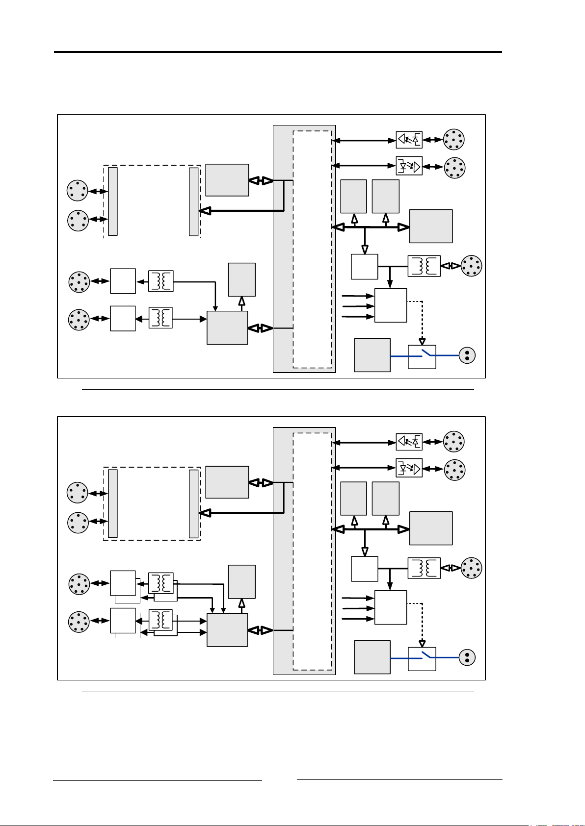
1.3 Block diagram .....................................................................6
1.4 Support...............................................................................7
1.5 Returning hardware............................................................8
2Installation.................................................................................8
2.1 Hardware installation .........................................................8
2.2 Software installation ..........................................................8
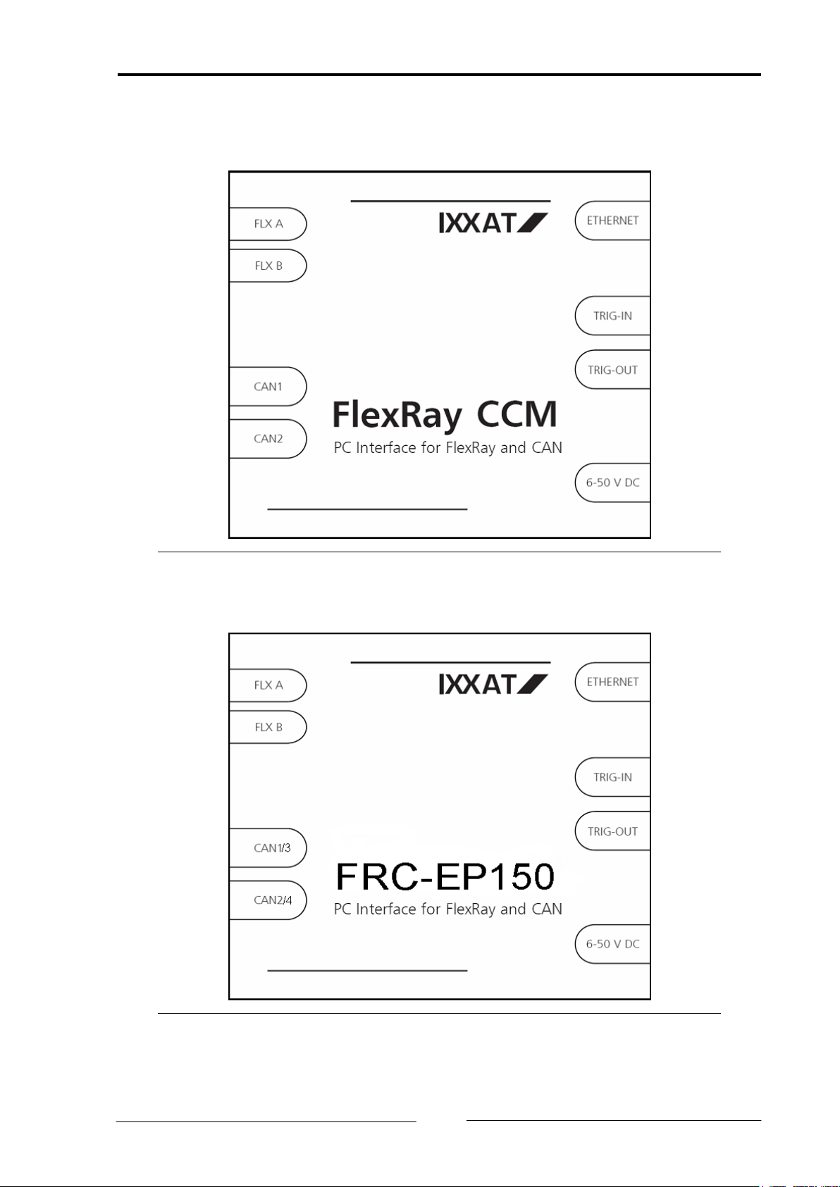
3Connections...............................................................................9
3.1 Pin assignment .................................................................10
3.1.1 FlexRay connector (FLX A & FLX B) ........................................... 11
3.1.2 FlexRay CCM CAN connector (CAN1 & CAN2) .......................... 12
3.1.3 FRC-EP150 CAN connector (CAN1/3 & CAN2/4)....................... 12
3.1.4 Power connector (6 - 50 V DC) ................................................ 13
3.1.5 Ethernet connector (ETHERNET)............................................... 14
3.1.6 Trigger/Digital-Out connector (TRIG-OUT)................................ 15
3.1.7 Trigger-In connector (TRIG-IN) ................................................. 15
3.2 Shielding...........................................................................16
3.3 Trigger/Digital output .......................................................17
3.4 Trigger input .....................................................................20
4Displays ...................................................................................21
5Firmware updates....................................................................22
Appendix ........................................................................................23
Technical specifications ...........................................................23
Ordering codes ........................................................................24
Accessories ..............................................................................25
Information on disposal of waste equipment.........................30
Information on EMC ................................................................30
Declaration of conformity .......................................................31
FCC Compliance.......................................................................32


Copyright IXXAT Automation GmbH FlexRay CCM Manual, Version 2.4
Introduction
5
1Introduction
1.1 Overview
The FlexRay CCM/FRC-EP150 is a powerful PC interface for the analysis, diagnos-
tics and stimulation of FlexRay and CAN networks.
This manual is intended to help you make full use of your interface. Please read
this manual before beginning with installation.
1.2 Features
•Measuring and analysis platform for FlexRay and CAN networks
•FlexRay connection via plug-in boards. Upgradeable to future protocol ver-
sions
•Current FlexRay protocol support via Freescale MFR4310
•FlexRay Dual Channel 2 x 10 MBit/s
•FlexRay Dual Communication Controller option available
•FlexRay bus connection via the Physical-Layer-Chip Philips TJA1080
•2 x CAN bus connection in accordance with ISO 11898-2 and 11898-3
switchable via software
•2 x CAN bus connection in accordance with ISO 11898-2 (FRC-EP150 only)
•Fast Ethernet 100 MBit/s
•Trigger interfaces: 4 x output, 2 x input
•Powerful microprocessor Power PC 866 with 133 MHz, 64 MByte RAM
and 32 MByte FLASH
•Highly integrated FPGA with one million gates for FIFO-memory, time stamp
and extended routing
•Two microcontrollers HCS12 for FlexRay and CAN communication
•All interfaces galvanically isolated
•Power supply from 6 to 50 V DC with overvoltage and reverse battery protec-
tion
•Housing and connectors suitable for use in automotive environment
•Open FlexRay and CAN PC driver interface (VCI) for Windows XP,
Windows 2000 and Windows Vista
Fig. 1-1/1-2 shows the block diagram of the basic board with all main interfaces
and Fig. 1-3/1-4 the block diagram of the FlexRay plug-in board. Depending on
the version of the FlexRay plug-in board, the architecture can be differently de-
signed.

Copyright IXXAT Automation GmbH FlexRay CCM Manual, Version 2.4
Introduction
6
1.3 Block diagram
FlexRay Module
FlexRay CCM
System
Controller
MPC866
Ethernet
Phy
Traffic
Detection/
Power on
U-Batt
100
MBit/s
Ethernet
Interface
Power
Supply
6,5 .. 50
V
CAN
Trans-
ceiver
CAN
Trans-
ceiver
CAN 1
CAN 2
Automatic
On Switch
FlexRay A
FlexRay B
Trigger In
Trigger Out
50 Pin Connector
Micro-
controller
HCS12
Flash RAM
CAN 1
FlexRayA/B
Data and
Control
Unit
(FPGA)
CAN 2
CAN 1
CAN 2
50 Pin Connector
RAM
Micro-
Controller
HCS12
Fig. 1-1: Block diagram of the FlexRay CCM
FlexRay Module
FRC-EP150
System
Controller
MPC866
Ethernet
Phy
Traffic
Detection/
Power on
U-Batt
100
MBit/s
Ethernet
Interface
Power
Supply
6,5 .. 50
V
CAN
Trans-
ceiver
CAN
Trans-
ceiver
CAN 1/3
CAN 2/4
Automatic
On Switch
FlexRay A
FlexRay B
Trigger In
Trigger Out
50 Pin Connector
Micro-
controller
HCS12
Flash RAM
CAN 1
FlexRayA/B
Data and
Control
Unit
(FPGA)
CAN 2
CAN 1
CAN 2
50 Pin Connector
RAM
Micro-
Controller
HCS12
CAN 4
CAN 3
Fig. 1-2: Block diagram of the FRC-EP150

Copyright IXXAT Automation GmbH FlexRay CCM Manual, Version 2.4
Introduction
7
FlexRay Module
FlexRay
Phy
TJA1080
FlexRay
Phy
TJA1080 Communi-
cation
Controller
50 Pin Connector
50 Pin Connector
Fig. 1-3: Block diagram of the FlexRay plug-in module
FlexRay Module Dual Controller
FlexRay
Phy
TJA1080
FlexRay
Phy
TJA1080 Communi
-cation
Controller
50 Pin Connector
50 Pin Connector
FlexRay
Phy
TJA1080
FlexRay
Phy
TJA1080
Communi
-cation
Controller
Fig. 1-4: Block diagram of the FlexRay plug-in module
1.4 Support
For more information on our products, FAQ lists and installation tips, please refer
to the support section of our website (http://www.ixxat.de), which also contains
information on current product versions and available updates.
If you have any further questions after studying the information on our website
and the manuals, please contact our support department. The support section on
our website contains the relevant forms for your support request. In order to faci-
litate our support work and enable a fast response, please provide precise infor-
mation on the individual points and describe your question or problem in detail.
If you would prefer to contact our support department by phone, please also
send a support request via our website first, so that our support department has
the relevant information available.

Copyright IXXAT Automation GmbH FlexRay CCM Manual, Version 2.4
Installation
8
1.5 Returning hardware
To enable fast, correct processing, please apply for an RMA number before re-
turning hardware using our on-line "RMA form", which you will find in the Sup-
port section on our website.
After applying for the RMA number, you will receive a return delivery note from
us, which you should enclose with the return delivery. If returns are made with-
out an RMA number or a return delivery note, we reserve the right to return the
delivery at your expense. A detailed description of the RMA procedure can be
found in the Support section on our website.
2Installation
2.1 Hardware installation
Connect the device to the supply voltage and connect it to a PC via Ethernet. Only
the cables of IXXAT may be used to operate the FlexRay CCM, see section "Acces-
sories".
2.2 Software installation
A PC driver is required to operate the device. For installation of the VCI driver un-
der Windows 2000/XP/Vista, please refer to the VCI installation manual.

Copyright IXXAT Automation GmbH FlexRay CCM Manual, Version 2.4
Connections
9
3Connections
Fig. 3-1: View of FlexRay CCM
Fig. 3-2: View of FRC-EP150

Copyright IXXAT Automation GmbH FlexRay CCM Manual, Version 2.4
Connections
10
3.1 Pin assignment
1
2
3
4 5
6
7
8
1
2
3
4 5
6
7
8
1
2
3 4
5
1
2
3 4
5
CAN1
CAN2
FLX
ON
RDY
ETH
FLX A FLX B CAN1 CAN2
IXXAT
FlexRay Channel A
FlexRay Channel B
CAN-Bus 1
CAN-Bus 2
Fig. 3-3: Connectors and LEDs on the front of the device (FR-CCM)
1
2
3
4 5
6
7
8
1
2
3
4 5
6
7
8
1
2
3 4
5
1
2
3 4
5
CAN1/3
CAN2/4
FLX
ON
RDY
ETH
FLX A FLX B CAN1/3 CAN2/4
IXXAT
FlexRay Kanal A
FlexRay Kanal B
CAN-Bus 1
CAN-Bus 2
Fig. 3-4: Connectors and LEDs on the front of the device (FRC-EP150)
1
2
3
4 5
6
7
8
1
2
3
4 5
6
7
8
6-50 V DC TRIG-OUT TRIG-IN ETHERNET
Power Trigger Out
Trigger In Ethernet
1
2
3
4 5
6
7
8
1
2
Fig. 3-5: Connectors on the back of the device
The following table provides an overview of the connectors used by the
device.

Copyright IXXAT Automation GmbH FlexRay CCM Manual, Version 2.4
Connections
11
Interface Vendor Type / remark
Power supply Lemo EPJ.1B.302.HLD
Ethernet Lemo EPD.1B.308.YLN
2 x CAN Lemo EPC.1B.308.HLN
2 x FlexRay
Lemo
EPB.0B.305.HLN
Trigger-In / Trigger-Out Lemo EPB.1B.308.HLN
Table 3-1: Connectors of the FlexRay CCM used
The interfaces are galvanically isolated from each other. In case of the FRC-EP150,
the CAN1/3- and CAN2/4-Interfaces do reside on the same potential. A more de-
tailed description is given in the relevant section. For shielding, please refer to
section 3.2.
3.1.1 FlexRay connector (FLX A & FLX B)
The differential signal pairs (BM and BP) for the FlexRay bus channels A and B are
connected to the FlexRay connectors. The connection assignment is listed in Table
3-2.
Pin Signal
1
2
3 4
5
1 Ground (FlexRay)
2
FlexRay Bus Minus (BM)
3 FlexRay Bus Minus (BM)
4 FlexRay Bus Plus (BP)
5 FlexRay Bus Plus (BP)
Table 3-2: Pin assignment of the FlexRay connector
The signal BM is connected to pin 2 and 3. These pins are connected with each
other in the device. The signal BP is connected to pin 4 and 5. These pins are
connected with each other in the device.
No bus terminal resistor is integrated in the device. If a bus terminal resistor is
required, it must be connected to the cable or connector. FlexRay cables with in-
tegrated terminal resistor are available as accessories.
The signal pair of the cable can be connected to pin 2 and pin 5. A bus terminal
resistor can be connected between pin 3 and pin 4.
With a Y-cable, the signal pair of cable 1 is connected to pin 2 and pin 5. The
signal pair of cable 2 is connected to pin 3 and pin 4. A suitable Y-cable is availa-
ble as accessories.
Always use cables suitable for the device, which are available in various versions,
see section "Accessories".

Copyright IXXAT Automation GmbH FlexRay CCM Manual, Version 2.4
Connections
12
The FlexRay bus is isolated galvanically from the other interfaces. Channels A and
B are connected to the same potential.
3.1.2 FlexRay CCM CAN connector (CAN1 & CAN2)
The CAN bus connection supports the physical bus access in accordance with ISO
11898-2 and ISO 11898-3. It is switched over via software.
The differential signal pair (CAN-low and CAN-high) and the ground are con-
nected to the CAN-connector.
Pin Signal
1
2
3
4 5
6
7
8
1 Reserved
2 CAN-low
3, 6 Ground (CAN)
4, 5 Reserved
7 CAN-high
8 CAN VBAT
Table 3-3: Pin assignment of the CAN connector
No bus terminal resistor is integrated for high-speed CAN ISO 11898-2. If a bus
terminal resistor is required, it must be connected to the cable or connector. Fle-
xRay instrument leads with integrated terminal resistor are available as accesso-
ries.
The low-speed CAN connection according to ISO 11898-3 is terminated via two
integrated terminal resistors of 2.2 kOhm each (RTH,RTL).
CAN VBAT is used to supply the terminal resistors of the CAN low-speed connec-
tion(RTH). This is necessary when the device is not supplied with voltage via the
Power connector or the device is in Sleep mode. A voltage of 5 V to 24 V can
then be supplied.
The two CAN buses are isolated galvanically from each other and from all other
interfaces.
3.1.3 FRC-EP150 CAN connector (CAN1/3 & CAN2/4)
The connections of the CAN-Interfaces CAN1 and CAN2 are equivalent as de-
scribed in chapter 3.1.2.
The CAN bus connection of the CAN-Interfaces CAN3 and CAN4 does support the
physical bus access in accordance with ISO 11898-2 only. The differential signal
pair (CAN-low and CAN-high) and the ground are connected to the CAN-
connector.

Copyright IXXAT Automation GmbH FlexRay CCM Manual, Version 2.4
Connections
13
Pin Signal
1
2
3
4 5
6
7
8
1 CAN3/4-Low
2 CAN1/2-low
3, 6 Ground (CAN)
4
CAN3/4-High
5 Reserved
7 CAN1/2-high
8 CAN VBAT
Table 3-4: Pin assignment of the CAN connector
No bus terminal resistor is integrated for high-speed CAN ISO 11898-2. If a bus
terminal resistor is required, it must be connected to the cable or connector. Fle-
xRay instrument leads with integrated terminal resistor are available as accesso-
ries.
The two CAN busses CAN1/3 and CAN2/4 are isolated galvanically from each
other and from all other interfaces.
3.1.4 Power connector (6 - 50 V DC)
The FlexRay CCM is supplied with direct current voltage of 6 V to 50 V. The
power supply input is protected against pole reversal and overvoltage.
Pin Signal 1
2
1 Supply voltage +
2
Ground
Table 3-5: Pin assignment of the power connector
Use the appropriate power supply cable for the device. This is also available sepa-
rately as an accessory.

Copyright IXXAT Automation GmbH FlexRay CCM Manual, Version 2.4
Connections
14
3.1.5 Ethernet connector (ETHERNET)
The Ethernet connector connects the signals for 10/100 base Ethernet.
Pin Signal
1
2
3
4 5
6
7
8
1 Connected with pin 2
2 Connected with pin 1
3 Connected with pin 7
4 RX+
5
TX-
6 RX-
7 Connected with pin 3
8 TX+
Table 3-6: Pin assignment of the ETHERNET connector
Ethernet is galvanically isolated from other interfaces.
Only use the appropriate Ethernet cable together with the device. This cable is
also available as an accessory.

Copyright IXXAT Automation GmbH FlexRay CCM Manual, Version 2.4
Connections
15
3.1.6 Trigger/Digital-Out connector (TRIG-OUT)
The 4 Trigger/Digital-Output signals are connected to the Trigger-Out connector.
Pin Signal
1
2
3
4 5
6
7
8
1
Trigger 1
2 Ground (Trigger out)
3 Trigger 2
4 Ground (Trigger out)
5 Trigger 3
6 Ground (Trigger out)
7 Trigger 4
8 Ground (Trigger out)
Table 3-7: Pin assignment of the TRIG-OUT connector
The Trigger output is galvanically isolated from the other interfaces.
A suitable trigger cable is available for the Trigger outputs. See section "Accesso-
ries".
3.1.7 Trigger-In connector (TRIG-IN)
The 2 Trigger input signals are connected to the Trigger-In connector.
Pin Signal
1
2
3
4 5
6
7
8
1 Trigger 1
2
Ground (Trigger in)
3 Trigger 2
4 Ground (Trigger in)
5-8 Not used
Table 3-8: Pin assignment of the TRIG-IN connector
The Trigger-In is galvanically isolated from the other interfaces.
A suitable cable is available for the Trigger inputs. See section "Accessories".

Copyright IXXAT Automation GmbH FlexRay CCM Manual, Version 2.4
Connections
16
3.2 Shielding
The device distinguishes between the signal ground (CANx_GND, FLX_GND,
TRGx_GND), the supply ground (GND) and the housing ground (PE). Each inter-
face has its own ground potential, as the interfaces are galvanically isolated from
each other. Fig. 3-6 shows an overview of the shields and of the potentials of the
individual interfaces.
The shields of CAN1, CAN2, FlexRay, Trigger-input, Trigger-output and Ethernet
are connected to the housing ground (PE) via RC-circuits and a varistor (VDR). The
shield is connected to the individual grounds via RC- circuits. Fig. 3-7 shows the
schematic of these RC-circuits
The isolation voltage of the shield to the PE is max. 50 V DC.
The isolation voltage of the signal ground against the shield and against the
supply ground as well as against other interfaces is max. 100 V DC.
The shielding of the power connector is connected directly to PE. The ground of
the power connector is only connected to the housing (PE) via RC-circuits
PE is designed as a closed ring around the PCB and connected to the housing via
the screw points and with EMC spring contacts.
Signal
Ground
Shield
Signal
Shield
FLX_GND
PE
Signal
Shield
CAN1_GND
PE
Signal
Shield
CAN2_GND
PE
TRGO_GND
TRGI_GND
Masse
Shield GND
PE
6,5 .. 50 V
Housing
Ground
Ground
Ground
Ground
Ground
FlexRay A
FlexRay B
CAN 1(/3)
CAN 2(/4)
Trigger Out
Trigger In
galvanical Isolation
Power
Housing
Signal
Shield
PE
Ethernet
Signal
Shield
PE
Signal
Shield
PE
Fig. 3-6: Shielding concept

Copyright IXXAT Automation GmbH FlexRay CCM Manual, Version 2.4
Connections
17
Fig. 3-7: Shielding connected with PE and ground
3.3 Trigger/Digital output
The functionality of each individual output can be defined via the FPGA register
“MPC866 Trigger Control Register”. Two different modes of operation can be
selected:
The Trigger mode is used for analysis and measurement of the real-time behavior
of the buses. Trigger conditions can be set via the software. When the configured
trigger condition is fulfilled, a voltage pulse appears on the trigger output. This
voltage pulse is generated in the device with an optocoupler and a transistor
output (see Fig. 3-9) and can be made visible, for example, with an oscilloscope.

Copyright IXXAT Automation GmbH FlexRay CCM Manual, Version 2.4
Connections
18
The following Fig. 3-8 shows the timing relation with the output signal. The trig-
ger pulse is an internal signal generated in the FlexRay CCM. The Trigger output is
connected externally to the Trigger-Out connector.
t f t r
0V
U Batt
Trigger puls
Trigger output
t w
Fig. 3-8: Trigger-Out timing
The voltage and timing parameters for the Trigger output are listed in the follow-
ing table.
Parameter Designation Value Unit of mea-
surement
U Batt Battery voltage 1.5 V
U Batt max* Maximum battery voltage* 60 V
t w Pulse width (width) typically 1 us
t f Fall time (fall) typically 5 us
t r Rise time (rise) typically 50 us
Table 3-9: Trigger-Out parameters
* The maximum operating voltage results from the electric strength of the opto-
coupler. The maximum power loss on the optocoupler and on the pre-resistor in
the device is restricted by the pulse-interval ratio.
The digital mode is used as user defined output. In this mode, the software is
able to switch the outputs into a defined state (“High” or “Low”). With a appro-
priate adaptation circuit, external loads (i.e. signal lamps, relays) can be switched
by software.

Copyright IXXAT Automation GmbH FlexRay CCM Manual, Version 2.4
Connections
19
Fig. 3-9: Internal Trigger/Digital-Out circuit
This output must be supplied with an external voltage via a resistor. The following
circuit (Fig. 3-10) can be connected to a Trigger output.
+
4.7 kOhm
U Batt
R
FlexRay CCM Oscilloscope
Fig. 3-10: Connection of an oscilloscope to Trigger-Out

Copyright IXXAT Automation GmbH FlexRay CCM Manual, Version 2.4
Connections
20
3.4 Trigger input
The device software provides stimulation functions via the Trigger input. The trig-
ger actions are configured via software. If a voltage pulse is supplied on the Trig-
ger input, the configured trigger action is executed. The supplied voltage pulse is
analyzed in the device via an optocoupler.
Fig. 3-11: Internal Trigger-In circuit
The voltage and timing parameters for the Trigger-In are given in Fig. 3-12 and
Table 3-10.
Trigger puls
t w
0 V
U in
Fig. 3-12: Trigger-In timing
Parameter Designation Value Unit of mea-
surement
U in min Minimum voltage 4 V
U in max Maximum voltage 42 V
t w min Pulse width 10 us
Table 3-10: Trigger-In parameters
Table of contents
Other IXXAT Recording Equipment manuals

IXXAT
IXXAT iPC-I 165 User manual

IXXAT
IXXAT tinCAN161 User manual

IXXAT
IXXAT VCI User manual

IXXAT
IXXAT CANblue User manual

IXXAT
IXXAT CAN@net II User manual

IXXAT
IXXAT iPC-I XC16/PCI User manual

IXXAT
IXXAT iPC-I XC16/PCI User manual

IXXAT
IXXAT PC-I 03 User manual

IXXAT
IXXAT USB-to-CAN compact User manual

IXXAT
IXXAT iPC-I 165/PCI User manual