IXXAT iPC-I 165 User manual

The expert for industrial and automotive communication
Hardware Manual
iPC-I 165
Intelligent PC/CAN Interface

IXXAT
Headquarter US Sales Office
IXXAT Automation GmbH IXXAT Inc.
Leibnizstr. 15 120 Bedford Center Road
D-88250 Weingarten USA-Bedford, NH 03110
Tel.: +49 (0)7 51 / 5 61 46-0 Phone: +1-603-471-0800
Fax: +49 (0)7 51 / 5 61 46-29 Fax: +1-603-471-0880
Internet: www.ixxat.de Internet: www.ixxat.com
Support
In case of unsolvable problems with this product or other IXXAT products
please contact IXXAT in written form by:
Fax: +49 (0)7 51 / 5 61 46-29
Copyright
Duplication (copying, printing, microfilm or other forms) and the electronic
distribution of this document is only allowed with explicit permission of
IXXAT Automation GmbH. IXXAT Automation GmbH reserves the right to
change technical data without prior announcement. The general business
conditions and the regulations of the license agreement do apply. All rights
are reserved.
Document number: 4.01.0045.20000
Version: 2.3

Contents
1Introduction................................................................................5
1.1 Overview ............................................................................. 5
1.2 Features............................................................................... 5
1.3 Block diagram ..................................................................... 6
2Installation ..................................................................................7
2.1 Hardware installation ......................................................... 7
2.2 Software installation .......................................................... 7
3Configuration .............................................................................8
3.1 Settings on the interface .................................................... 8
3.1.1 Setting the base address ...........................................................9
3.1.2 Setting the PC interrupt ............................................................9
3.1.3 16 bit access mode.................................................................10
3.1.4 Zero wait states ......................................................................10
3.1.5 Bootstrap loader .....................................................................11
3.1.6 Reserved switches ...................................................................11
3.1.7 Providing current supply via CAN plug.....................................11
3.1.8 Bus termination resistors .........................................................12
3.1.9 Reset button and LED .............................................................12
3.2 Design of the CAN plugs................................................... 12
3.2.1 CAN bus connector.................................................................12
3.2.2 Serial RS232 interface .............................................................15
Appendix..........................................................................................16
Appendix A .............................................................................. 16
Technical Data .......................................................................... 16
EMC test................................................................................... 16
Appendix B............................................................................... 17
Delivery settings ...................................................................... 17
Appendix C............................................................................... 18
Supply sources for data sheets................................................ 18
Copyright IXXAT Automation GmbH iPC-I 165 - Manual, Version 2.3
3


Introduction
1 Introduction
1.1 Overview
With the IXXAT PC/CAN interface iPC-I 165 you have purchased a high-quality
electronic component which has been developed and manufactured according to
the latest technological standards.
The aim of this manual is to help you familiarize yourself with your interface, also
referred to in the following as iPC-I 165. Please read this manual before begin-
ning with the installation.
1.2 Features
• Design as ISA board
• 16 bit memory mapped access (12 Kbytes address space are required)
• Base address configurable via DIP switch (from C000h to FE00h in 16k steps)
• PC interrupts configurable via jumper (IRQ 3, 4, 5, 7, 9, 10, 11, 12, 14, 15)
• Microcontroller Siemens SAB C165 clocked with 20 MHz
• One ore two CAN lines with Philips SJA1000 and/or INTEL 82527 clocked with
16 MHz
• 8 Kbytes Dual-Port-RAM, 16 semaphore registers
• 512 Kbytes RAM (optional up to 2 Mbytes)
• 512 Kbytes Flash (optional up to 1 Mbytes)
• CAN bus connector according to ISO/IS 11898 on board (optional galvanic
decoupled); alternative bus interfaces can be realized via piggy-back board
• Optional CAN protection circuits on-board
• Optional developer equipment with reset button, LED and DIP switch for spe-
cial functions
• Download of INTEL HEX files into the SRAM or FLASH
• EMC safe design of circuit board (6 layer PCB)
Copyright IXXAT Automation GmbH iPC-I 165 - Manual, Version 2.3
5
Introduction
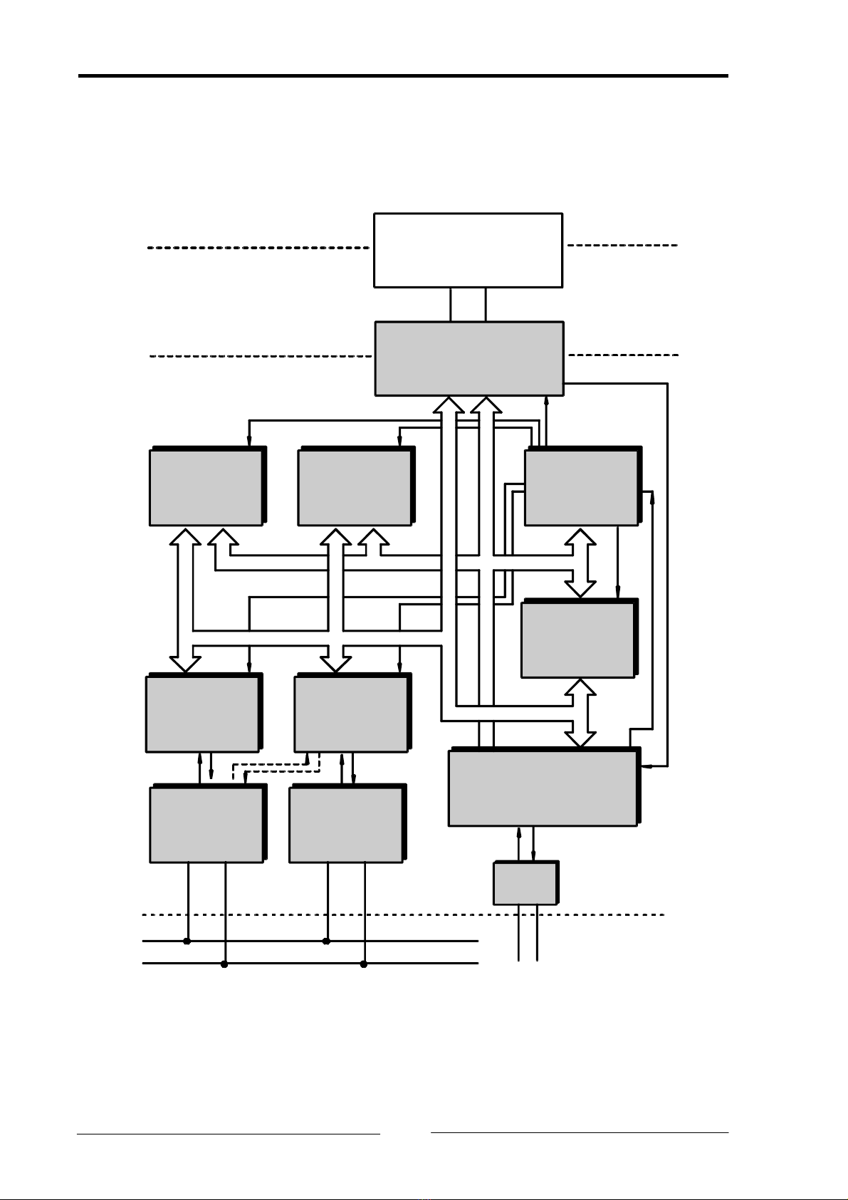
1.3 Block diagram
Interfacelogic
(DPRAMand Flags)
Flash
(max. 1MB)
Microcontroller
SAB C165LM
CAN Bus
A 0..23
ISA-Bus
PC
iPC-I 165
AD0..15
A 0..23
SRAM
(max. 2 MB) Address
Decoder
2. CAN
Controller
82C200/82527
CAN Bus-
Interface
EPROM
32 kB
RESET
RS232
TxD RxD
CAN High
CANLow
1. CAN
Controller
82C200/82527
CAN Bus-
Interface
AD0..15
CS
Copyright IXXAT Automation GmbH iPC-I 165 - Manual, Version 2.3
6

Installation
2 Installation
2.1 Hardware installation
For all work on the PC and interface, you must be statically discharged. The work
must be carried out on an earthed, anti-static work-mat.
Carry out the following work in sequence:
(1) Establish a free memory segment on the PC of at least 16 kbyte in the range
< 1MB (ISA memory range) and a free IRQ. For this, read the manual of
your PC.
(2) Set this memory segment and the IRQ on the interface, as described in Sec-
tion 3.1.
(3) Switch off the PC and remove the mains plug.
(4) Open the PC according to the instructions of the PC-manufacturer and de-
termine a suitable plug-in space.
The interface is designed according to the PC-standard and can be easily
built into the computer. Do not use force when plugging in.
(5) Ensure that the interface is held safely in place in the PC.
(6) If your interface is assembled with 2 separate CAN circuits, you must fix the
additional slot plate and plug in the header on the interface (see Section
3.2).
(7) Close the PC; the hardware installation is now completed.
2.2 Software installation
To operate the interface, a driver is required. For the installation of the CAN driver
VCI please read the VCI installation manual.
Copyright IXXAT Automation GmbH iPC-I 165 - Manual, Version 2.3
7

Configuration
3 Configuration
3.1 Settings on the interface
The diagram Fig. 3-1 shows the positions of the plugs and jumpers on the inter-
face board.
Ground pin
First CAN line
Second
CAN line
Fig. 3-1: iPC-I 165 interface board
Serial
interface
Copyright IXXAT Automation GmbH iPC-I 165 - Manual, Version 2.3
8

Configuration
3.1.1 Setting the base address
To set the base address the switches 1 to 4 of the DIP switch SW1 are used. The
following table shows the possible settings (default = factory setting).
Base address SW1
1
SW1
2
SW1
3
SW1
4
C000h ON ON ON ON
C400h ON ON ON OFF
C800h ON ON OFF ON
CC00h ON ON OFF OFF
D000h (default) ON OFF ON ON
D400h ON OFF ON OFF
D800h ON OFF OFF ON
DC00h ON OFF OFF OFF
E000h OFF ON ON ON
E400h OFF ON ON OFF
E800h OFF ON OFF ON
EC00h OFF ON OFF OFF
F000h OFF OFF ON ON
F400h OFF OFF ON OFF
F800h OFF OFF OFF ON
FC00h OFF OFF OFF OFF
The address zone of the interface must not overlap with any other sys-
tem components in the PC.
3.1.2 Setting the PC interrupt
The required interrupt is set with the jumper board JP1 by connecting the jumper
pair belonging to the requested IRQ.
Only one interrupt may be selected for the iPC-I 165!
If no interrupt is required, no pin may be bridged on JP1. The factory setting of
the interface is IRQ 5.
Copyright IXXAT Automation GmbH iPC-I 165 - Manual, Version 2.3
9

Configuration
It should be ensured that no other system component is occupying the selected
interrupt, except for cards which work with shared interrupts.
In PC systems it is possible that several cards share an interrupt. Further informa-
tion on this subject can be found in the hardware manuals for the PC. The
iPC-I 165 supports shared interrupts by enabling the level of the interrupt im-
pulses to be adjusted with switch 2 of the DIP switch SW3. For shared interrupts
the DIP switch SW3-2 must be set to OFF position.
IRQ level SW3
2
Low impulse (default) OFF
High impulse ON
3.1.3 16 bit access mode
By setting the switch 5 of DIP switch SW1 to OFF, the 16 bit access for the
iPC-I 165 can be activated. Then iPC-I 165 will be accessed with 16 bit bus cycles
from the ISA bus. If the 16 bit access is switched off the interface is accessed with
8 bit wide bus cycles.
Access mode SW1
5
16 bit (default) OFF
8 bit ON
3.1.4 Zero wait states
By setting the switch 6 of DIP switch SW1 to OFF, a shortened ISA bus cycle (0
wait states) can be activated. If SW1-6 is set to ON, the PC performs a standard
bus cycle.
Wait states SW1
6
No wait states OFF
With wait states (default) ON
Copyright IXXAT Automation GmbH iPC-I 165 - Manual, Version 2.3
10
Table of contents
Other IXXAT Recording Equipment manuals

IXXAT
IXXAT iPC-I XC16/PCI User manual

IXXAT
IXXAT iPC-I 165/PCI User manual

IXXAT
IXXAT CANblue User manual

IXXAT
IXXAT iPC-I 320/PCI II User manual

IXXAT
IXXAT PC-I 04/104 User manual

IXXAT
IXXAT CAN-IB Series User manual

IXXAT
IXXAT USB-to-CAN II User manual

IXXAT
IXXAT VCI User manual

IXXAT
IXXAT USB-to-CAN compact User manual

IXXAT
IXXAT CAN@net II User manual


