manuals.online logo
Brands
  1. Home
  2. •
  3. Brands
  4. •
  5. JABSCO
  6. •
  7. Water Pump
  8. •
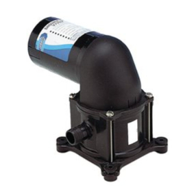
  9. JABSCO 30296 Series User manual

JABSCO 30296 Series User manual

This manual suits for next models

2

Other JABSCO Water Pump manuals

JABSCO 37202-2 User manual

JABSCO

JABSCO 37202-2 User manual

JABSCO 11860-0005 User manual

JABSCO

JABSCO 11860-0005 User manual

JABSCO 29200-0120 User manual

JABSCO

JABSCO 29200-0120 User manual

JABSCO 31595-009 User manual

JABSCO

JABSCO 31595-009 User manual

JABSCO 32605 Series User manual

JABSCO

JABSCO 32605 Series User manual

JABSCO 36680-2 Series User manual

JABSCO

JABSCO 36680-2 Series User manual

JABSCO 30510-3 Series User manual

JABSCO

JABSCO 30510-3 Series User manual

JABSCO 1285O SERIES User manual

JABSCO

JABSCO 1285O SERIES User manual

JABSCO 17860 Series User manual

JABSCO

JABSCO 17860 Series User manual

JABSCO 18670 Series User manual

JABSCO

JABSCO 18670 Series User manual

JABSCO 30520-0001 User manual

JABSCO

JABSCO 30520-0001 User manual

JABSCO 18590 Series User manual

JABSCO

JABSCO 18590 Series User manual

JABSCO 30580-0 Series User manual

JABSCO

JABSCO 30580-0 Series User manual

JABSCO 29200-0120 User manual

JABSCO

JABSCO 29200-0120 User manual

JABSCO 52700 User manual

JABSCO

JABSCO 52700 User manual

JABSCO 37202-2 User manual

JABSCO

JABSCO 37202-2 User manual

JABSCO 18690-0000 User manual

JABSCO

JABSCO 18690-0000 User manual

JABSCO 33745-0000 User manual

JABSCO

JABSCO 33745-0000 User manual

JABSCO 30510-1003 User manual

JABSCO

JABSCO 30510-1003 User manual

JABSCO 31395-0092 User manual

JABSCO

JABSCO 31395-0092 User manual

JABSCO 23920-2403 User manual

JABSCO

JABSCO 23920-2403 User manual

JABSCO 36960-2 Series User manual

JABSCO

JABSCO 36960-2 Series User manual

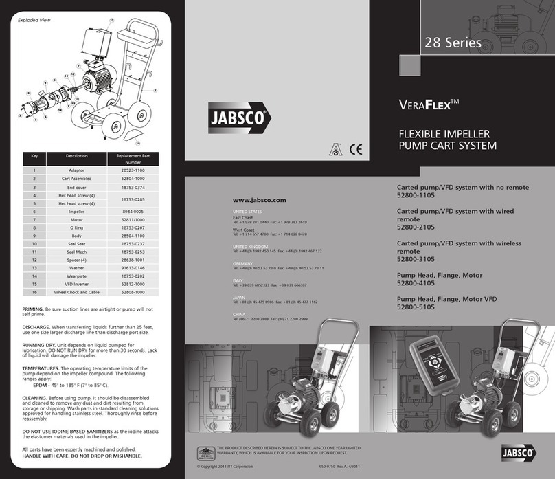
JABSCO 28 Series User manual

JABSCO

JABSCO 28 Series User manual

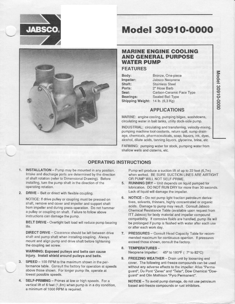
JABSCO 30910-0000 User manual

JABSCO

JABSCO 30910-0000 User manual

Popular Water Pump manuals by other brands

Watershed Innovations HYDRAPUMP SMART FLEX Instructional manual

Watershed Innovations

Watershed Innovations HYDRAPUMP SMART FLEX Instructional manual

Graco Modu-Flo AL-5M instructions

Graco

Graco Modu-Flo AL-5M instructions

Messner MultiSystem MPF 3000 operating instructions

Messner

Messner MultiSystem MPF 3000 operating instructions

Xylem Bell & Gossett WEHT0311M Installation, operation and maintenance instructions

Xylem

Xylem Bell & Gossett WEHT0311M Installation, operation and maintenance instructions

WilTec 50739 Operation manual

WilTec

WilTec 50739 Operation manual

Franklin Electric Little Giant 555702 HRK-360S instruction sheet

Franklin Electric

Franklin Electric Little Giant 555702 HRK-360S instruction sheet

Ingersoll-Rand PD02P Series Operator's manual

Ingersoll-Rand

Ingersoll-Rand PD02P Series Operator's manual

VS ZJ Series Operating	 instruction

VS

VS ZJ Series Operating instruction

Flotec FPZS50RP owner's manual

Flotec

Flotec FPZS50RP owner's manual

SKF Lincoln FlowMaster II User and maintenance instructions

SKF

SKF Lincoln FlowMaster II User and maintenance instructions

Xylem Lowara LSB Series Installation, operation and maintenance instructions

Xylem

Xylem Lowara LSB Series Installation, operation and maintenance instructions

Water Duro Pumps DCJ500 Operating & installation instructions

Water

Water Duro Pumps DCJ500 Operating & installation instructions

Action P490 Operating instructions & parts manual

Action

Action P490 Operating instructions & parts manual

Flo King Permacore Reusable Carbon Bag Disassembly. & Cleaning Instructions

Flo King

Flo King Permacore Reusable Carbon Bag Disassembly. & Cleaning Instructions

ARO ARO PD15P-X Operator's manual

ARO

ARO ARO PD15P-X Operator's manual

Pumptec 112V Series Operating instructions and parts manual

Pumptec

Pumptec 112V Series Operating instructions and parts manual

Virax 262070 user manual

Virax

Virax 262070 user manual

Neptun NPHW 5500 operating instructions

Neptun

Neptun NPHW 5500 operating instructions

manuals.online logo
manuals.online logoBrands
  • About & Mission
  • Contact us
  • Privacy Policy
  • Terms and Conditions

Copyright 2025 Manuals.Online. All Rights Reserved.

Model 30296-Series
Model 30296-Series
SHOWER SUMP PUMP
FEATURES
●Multiple intake ports:
2 each: 3/4"
1 each: 1", 1-1/8" & 1-1/2"
●Evacuates 2-3 showers simultaneously
●Extra large strainer is easy to clean
●Clear cover for easy inspection
●Discharge check valve prevents back-flow
SPECIFICATIONS
Flow: Maximum 13 GPM
At 3' of head 10-1/2 GPM
At 6' of head 8 GPM
Discharge Port: 3/4"
AMP Draw: 4 maximum
Dimensions: 9-3/8" (238mm) x 11-1/4" (286mm)
including length of intake ports x
5-1/8" (130mm) high
VARIATIONS AVAILABLE
MODEL NO. DESCRIPTION
30296-2012 12 Volt
30296-2024 24 Volt
OPERATION
The Jabsco Shower Sump Pump consists of an automatic
float switch and powerful submersible evacuation pump
fixed inside a compact reservoir with integral, easy to
clean strainer that protects the system from debris. The
switch automatically activates the pump when water
drains in from a shower and keeps it running until the
reservoir is evacuated. The high capacity of the pump
makes the system capable of handling up to three
showers simultaneously.
MAINTENANCE
The Shower Sump Pump needs no regular maintenance
other than an occasional inspection and, if required, the
removal of excessive debris that may have accumulated
in the reservoir’s intake strainer. Visual inspection is
easy through the reservoir’s clear top cover. If excessive
amounts of debris are trapped inside the intake strainer
simply remove the four screws securing the top cover
and lift off the top. Grasp the round strainer in the middle
and compress the strainer then slide it to the center of
the reservoir (toward the pump and switch) and out of
the strainer locators on each end. Remove the debris
and rinse out the strainer. Replace the strainer in the
reservoir and reattach the reservoir’s top cover.
U.S.A.
Jabsco
20 Icon
Foothill Ranch, CA 92610-3000
Tel: 949.609.5106
Fax: 949.859.1254
UNITED KINGDOM
Jabsco
Bingley Road, Hoddesdon
Hertfordshire EN11 OBU
Tel: +44 (0) 1992 450145
Fax: +44 (0) 1992 467132
CANADA
Fluid Products Canada
55 Royal Road
Guelph, Ontario N1H 1T1
Tel: (519) 821.1900
Fax: (519) 821.2569
JAPAN
NHK Jabsco Company Ltd.
3-21-10, Shin-Yokohama
Kohoku-Ku, Yokohama, 222
Tel: 045.475.8906
Fax: 045.475.8908
GERMANY
Jabsco GmbH
Oststrasse 28
22840 Norderstedt
Tel: +49-40-53 53 73 -0
Fax: +49-40-53 53 73 -11
THE PRODUCTS DESCRIBED HEREIN ARE
SUBJECT TO THE JABSCO ONE YEAR LIMITED
WARRANTY, WHICH IS AVAILABLE FOR YOUR
INSPECTION UPON REQUEST.
© Copyright 2002, ITT Industries Printed in U.S.A. All Rights Reserved Form: 43000-0704 M-1354 Rev. A 8/2002
5-1/8"
(130 mm)
9-3/8" (238 mm) 11-1/4" (286 mm)
DIMENSIONAL DRAWING
Inches (Millimetres)
INSTALLATION & PLUMBING
Select a location for the Shower Sump Pump that is
lower than the drain connection at the shower pan and is
easily accessible for periodic inspections of the inlet
strainer. It is best to have a minimum drop of 1" for each
6 feet (2-1/2cm per 1M) of run of the drain hose from the
shower. The drain hose should drop continuously from
the shower pan to the Shower Sump Pump with no dips
in the plumbing that would trap water. Before installing
the reservoir, determine which inlet port fitting(s) will be
used and is(are) the correct size for the shower drain
hose(s), then cut off the closed end of the selected port
fitting(s) with a hack saw. Do not cut off the ends of
port fittings that are not intended to be used.
The shower sump reservoir should be secured to a solid
flat mounting surface with either short stainless steel
screws or affixed with a quality marine sealant with good
adhesive characteristics (such as Rule* Elastomeric
Marine Sealer) used as an adhesive. If securing the
reservoir with screws to the bottom of the vessel, ensure
the penetration of the screw is significantly less than the
thickness of the hull. Mark the location of at least four of
the reservoir’s mounting holes and then very carefully
drill pilot holes for the screws. It is helpful to wrap the drill
bit with a piece of tape so the tape’s edge indicates the
maximum depth of the hole to serve as a stop indicator.
If securing the reservoir with a sealant, apply a liberal
bead of the sealant along the line of the mounting holes
on the underside of the mounting tabs. Press the
reservoir into place and leave it undisturbed until the
sealant has cured (check the manufacturer’s
recommended cure time).
The Shower Sump Pump’s 3/4" (19mm) discharge hose
should climb continuously and be attached to a thru-hull
fitting that remains well above the vessel’s waterline at
all angles of heel and trim. Sailboats normally discharge
through or just below the transom. The discharge
plumbing must not have any dips in it that would create
a water trap that will retain water in the hose. If this
occurs the Shower Sump Pump might airlock. To
maximize pump performance, the discharge plumbing
should be kept as short and straight as possible. Attach
all hoses to their respective hose barbs with stainless
steel band clamps. It is recommended that all plumbing
be secured in place about every 18" to 24" (45cm to
60cm) along the length of its run.
*Rule® is a registered trademark of ITT Industries.
WIRING
All wiring connections must be made with mechanical
locking connectors (crimp type) and secured in a dry
location well above bilge areas where water may collect.
To better protect butt connections made in a humid
marine environment, it is advisable to seal the connections
with a small amount of marine sealant. Connect the gray
wire lead (from the switch) to a positive (+) power source
using a minimum16 gauge (1.5mm2) conductor**. This
conductor should originate from an overload protected
distribution panel where the conductor (and complete
circuit) is protected by a 5 amp fuse or circuit breaker for
12 Volt pumps and a 2-1/2 amp fuse or breaker for 24
Volt pumps. Connect the black lead (from the pump) to
battery negative.
** 16 gauge (1.5mm2) wire is large enough for total 12
Volt circuit lengths (combined positive (+) and negative
(-) conductors) of up to 50 feet (15M). Circuits longer
than this should use larger wire. Between 50 and 90 feet
(15M and 27M) use 14 gauge (2.5mm2) and between 90
and 130 feet (27M and 40M) use 12 gauge (4mm2). 24
Volt circuits can use 16 gauge (1.5mm) wire for total circuit
lengths of up to 100 feet and should use 14 gauge
(2.5mm) if the circuit length is between 100 and 150 feet.
Pump
Switch
Black
Gray
Overload
Protected
Distribution
Panel
Battery
WIRING DIAGRAM