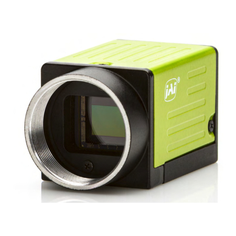
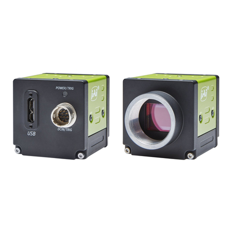
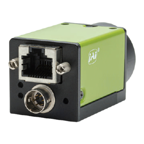
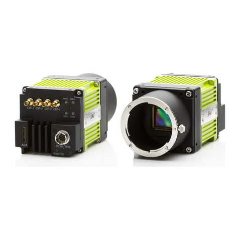
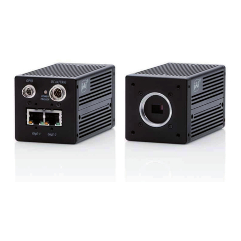
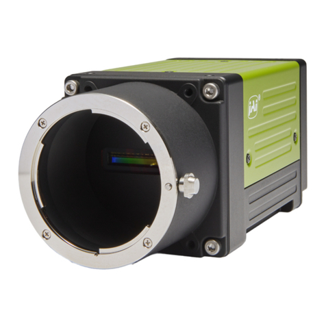
BM-141GE / BB-141GE
2
Table of Contents
1. General.............................................................................................. 4
2. Camera nomenclature............................................................................. 4
3. Main Features ...................................................................................... 5
4. Locations and Functions .......................................................................... 6
4.1. Locations and functions..................................................................................6
4.2. Flange back adjustment .................................................................................7
5. Pin Assignment ..................................................................................... 8
5.1 12-pin Multi-connector (DC-in/GPIO/Iris Video).....................................................8
5.2 Digital Output Connector for Gigabit Ethernet ......................................................8
5.3 D-sub 9 pin connector for GPIO (Auxiliary)...........................................................8
5.4 Internal DIP switch........................................................................................9
6. GPIO (Inputs and outputs) .......................................................................10
6.1. Overview.................................................................................................. 10
6.1.1 LUT (Cross Point Switch) ........................................................................... 11
6.1.2 12-bit Counter........................................................................................ 11
6.1.3 Pulse Generators (0 to 1)........................................................................... 11
6.2 Opto-isolated Inputs/Outputs......................................................................... 11
6.2.1 Recommended External Input circuit diagram for customer ................................ 12
6.2.2 Recommended External Output circuit diagram for customer .............................. 12
6.2.3 Optical Interface Specifications................................................................... 12
6.3. Inputs and outputs table............................................................................... 13
6.4. Configuring the GPIO module (register settings) ........................................................ 14
6.4.1 Input /Output Signal Selector ..................................................................... 14
6.4.2 12bit counter......................................................................................... 15
6.4.3 Pulse generators (19 bit x 2).......................................................................... 16
6.5. GPIO programming examples ............................................................................... 18
6.5.1 GPIO Plus PWC shutter.............................................................................. 18
6.5.2 Internal Trigger Generator......................................................................... 19
7. GigE Vision Streaming Protocol (GVSP) ........................................................20
7.1. Digital Video Output (Bit Allocation)..................................................................... 20
7.2. Bit Allocation (Pixel Format / Pixel Type) – BM-141GE (monochrome)............................ 20
7.2.1 GVSP_PIX_MONO8 (8bit)......................................................................... 20
7.2.2 GVSP_PIX_MONO10 (10bit)..................................................................... 20
7.2.3 GVSP_PIX_MONO10_PACKED (10 bit)............................................................... 21
7.2.4 GVSP_PIX_MONO12 (12 bit).......................................................................... 21
7.2.5 GVSP_PIX_MONO12_PACKED (12 bit)............................................................... 21
7.3. Bit Allocation (Pixel Format / Pixel Type) – BB-141GE (Bayer mosaic color)..................... 21
7.3.1 GVSP_PIX_BAYRG8 “BayreRG8 “............................................................... 21
7.3.2 GVSP_PIX_BAYRG10 “Bayer RG10”................................................................. 21
7.3.3 GVSP_PIX_BAYRG12 “ Bayer RG12” ................................................................ 22
7.3.4 GVSP_PIX_BAYGB8 “Bayer GB8” ............................................................... 22
7.3.5 GVSP_PIX_BAYGB10 “ Bayer GB10” ................................................................ 22
7.3.6 GVSP_PIX_BAYGB12 “ Bayer GB12” Odd Line.............................................. 22
8. Functions and Operations........................................................................24
8.1. GigE Vision Standard Interface............................................................................ 24
8.2. Recommended Network Configurations ................................................................. 24
8.2.1 Verified Network Interface Cards (NICs) ..................................................... 24
8.2.2 Video data rate (network bandwidth) ............................................................. 25
8.2.3 Disable Firewalls.................................................................................. 28
8.2.4 Enabling Jumbo Frame ............................................................................... 28
8.2.5 Setting Receive Descriptors .................................................................... 30
8.2.6 Interrupt Moderation rate ...................................................................... 31
8.2.7 Calculating and setting Inter-Packet Delay.................................................. 31
8.2.8 Confirm the Filter Driver is used .............................................................. 32
