manuals.online logo
Brands
  1. Home
  2. •
  3. Brands
  4. •
  5. Jamara
  6. •
  7. Motorized Toy Car
  8. •
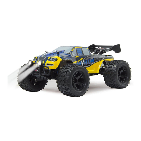
  9. Jamara Akron BL RTR 2,4 GHz User manual

Jamara Akron BL RTR 2,4 GHz User manual

Akron BL RTR 2,4 GHzNo. 05 3265 BL LiPo
31/15
FR - Notice d’assemblage
GB - Instruction
FR - Remarques générales
La société Jamara e. K. n’est pas responsable de dommages, que ce soit au niveau du modèle ou causé par celui-ci,
résultant d’une utilisation non appropriée. Seul le client est responsable concernant la mise en oeuvre et l’utilisation
conforme du matériel; cela va de l’assemblage, en passant par la charge des accus et allant jusqu’au choix du lieu
d’utilisation. Pour cela, veillez à lire attentivement la notice d’utilisation, elle contient d’importantes informations ainsi
que les consignes de sécurité.
GB - General information
Jamara e.K. is not liable for any damage caused to the product itself or through this, provided this is due to improper
operation or handling errors. The Customer alone bears the full responsibility for the proper use and handling, including
without limitation, the assembly, the charging process, the use and choice of the operation area. Please refer to the
operating and user instructions, it contains important information and warnings.
FR - Déclaration de conformité
Par la présente, la société Jamara e.K. déclare que le modèle réduit “Akron BL RTR 2,4 GHz, No. 053265“ est conforme
en tous points avec les exigences fondamentales et les autres dispositions concernées des directives
1999/5/CE, 2011/65/UE.
Vous pourrez également trouver des informations sur notre site Internet: www.jamara-shop.com/Conformity
GB - Certicate of Conformity
JAMARA e.K. hereby declares that „Akron BL RTR 2,4 GHz, No. 053265“ follow the regulations and requirements as
well as any ther relivant directives of the EEC directive 1999/5/EC and 2011/65/EU.
Further information can also be found at: www.jamara-shop.com/Conformity
FR - Consignes de recyclage
Veuillez respecter les consignes de recyclage des accus et/ou piles. Veuillez ne jeter que des piles/
accus vides dans les bacs de collecte que vous trouverez dans différents commerces ou au centre de
recyclage de votre commune.
GB - Disposal restrictions
Please care for a environmental correct and legal way of disposing the batteries and/or accus. Please, only throw away
empty battery packs into the collect-boxes in your local shops or commune.
FR - Ce modèle réduit n’est pas un jouet!
N’est pas adapté pour les personnes de moins de 14 ans.
Attention: Tenir impérativement les enfants de moins de 36 mois hors de portée de l’article.
RISQUE D’ETOUFFEMENT! Contient de petits éléments pouvant être ingérés.
GB - This model is not a toy!
Not suitable for people under 14 year.
Warning: Keep away necessarily children under 36 months. RISK OF SUFFOCATION!
Contains small parts which can be swallowed.
FR
Attention!
Avant l’utilisation:
Allumez en premier le modèle réduit puis seulement l’émetteur.
Après l’utilisation:
Eteignez en premier le modèle réduit puis votre radiocommande.
GB
Attention!
Before operating:
Switch the transmitter on rst then the model.
When nisished:
First switch off the model then the transmitter.
FR - Outils conseillés | GB - Recommended Tool
No. 28 1785
Alésoir conique p. carosseries
Hub drill for bodywork
No. 19 0065
Appareil de mesure d’inclinaison
Camber adjusting Tool
No. 19 0060
Cales de hauteur
Height lange
No. 23 2060
Bande adhésive double
Doublesided power tape
No. 23 2423
Frein let moyen
Nut lock medium strength
No. 23 0409 20 g „Wheel blood“
Colle pour roue
Rim Glue
No. 28 1904 75 ml Louise
Huile pour amortisseur
Shock-Oil Louise
No. 23 0461 400 ml
Mouse de nettoyage spécial
Special cleaning foam
No. 50 5401 petit/small
Clips de carrosserie
Body clips
No. 15 3055
X-Peak 80 BAL
Chargeur
Charger
No. 19 3130
Banc de montage avec plateau
tournant
Car Stand rotatable
No. 19 7595
Outils 12in1
Tool 12in1
No. 15 3058
X-Peak 80 BAL Pult
Chargeur
Charger
No. 19 7598
Tournevis 24in1
Ratchet screwdriver 24in1
No. 15 3060
X-Peak 50 BAL
Chargeur
Charger
No. 05 9273 1:10
Clips de carrosserie
Body clips
No. 28 17817 Louise
Alésoir conique p. carosseries
Body reamer with cap and sizes
No. 15 3070
X-Peak BAL Touch USB
Chargeur
Charger
2
FR - Premiers pas
Assurez-vous d’avoir toutes les pièces prévues dans le kit. Emetteur, modèle,
chargeur, accu de propulsion (en place).
Dans un premier temps il faut charger l’accu de propulsion. Branchez le char-
geur sur une prise secteur 230V. Connectez celui-ci avec l’accu de propulsion.
Si le connecteur du chargeur et le connecteur de l’accu ne devait pas cor-
respondre vous avez un adaptateur à votre disposition dans le kit. La durée
moyenne de charge de l’accu de propulsion déchargé livré dans le kit est
d’environ 6 - 8 heures (LiPo 5 - 7 heures).
Placez 8 piles type AA ou accus correspondants dans l’émetteur. Si vous uti-
lisez des accus pour alimenter l’émetteur il faut tout d’abord les charger avec
un accu acheté séparément.
Lisez attentivement le chapitre concernant votre radiocommande et ses élé-
ments de commandes.
Mettez en route l’émetteur et assurezvous que les trims soient bien en posi-
tion de neutre pour chaque fonction. Vous avez acheté un modèle RTR. De
ce fait votre voiture est préparée en grandes lignes pour être utilisé de suite.
Néanmoins il est important de véri er avant et après chaque utilisation qu’il
n’y ait pas de dégâts mécaniques ou de problèmes électriques. De même il
faut contrôler toutes les pièces mobiles qu’elles soient libres de toutes con-
traintes, sans jeu et que toutes les vis soient correctement serrées. Mettez en
place l’accu de pro dans son compartiment. Veillez à ce que le support d’accu
soit à nouveau bien  xé avec les deux goupilles et que l’accu de propulsion
est bien  xé dans son support sans grand jeu. Connectez l’accu de propulsi-
on avec le régulateur du modèle. Tenez la voiture en l’air au cas où le moteur
démarrerait brutalement lors de la mise en marche. Mettez en marche le régu-
lateur avec le bouton On/Off. Posez le modèle sur le sol et testez le bon fon-
ctionnement des différentes commandes. Directionnel gauche/droite, vitesse
avant/arrière. Si les roues ne devaient pas être droites vers l’avant alors que
le volant de l’émetteur est au centre il est possible de réci er cette position à
l’aide du trim sur l’émetteur.
Trim L/R = direction
Trim V/R = avant/arrière
Si les roues devaient tourner en avant ou en arrière alors que vous n’avez pas
touché à la commande des gaz, il faut compenser cette action en utilisant le
trim de la fonction gaz jusqu’à ce que les roues restent immobiles. Nous vous
conseillons maintenant d’activer la fonction Failsafe de votre récepteur. Cette
fonction est désactivée en sortie d’usine.
Vous pouvez activer la fonction Failsafe en laissant le manche des gaz de
l’émetteur en position de neutre (voir chapitre Fail Safe) et en appuyant sur
la touche Failsafe de votre récepteur jusqu’à ce que la LED clignote puis en
relâchant la touche. N’activez cette fonction qu’avec le manche des gaz
en position de neutre pour une voiture électrique a n que la fonction
gaz du modèle, en cas de perte de signal, se place automatiquement en
position ralentie dé nie au préalable.
Maintenant vous pouvez effectuer un circuit test avec votre voiture. Si ce mo-
dèle est votre première voiture radiocommandée nous vous conseillons de
faire rouler votre modèle sur une petite piste de test a n de vous familiariser
avec les différentes fonctions de celui-ci et de votre émetteur.
Attention!
Votre modèle possède un système d’accrochage des roues avant type Pi-
vot. Cela a un bon nombre d’avantages. Celui-ci est très robuste et facile
d’entretien. En sortie d’usine les réglages sont effectués de telle manière que
l’écartement des roues ne permet pas aux axes d’entraînements de sortir de
son logement. Naturellement, comme pour toutes les voitures, dans la phase
de rodage toutes les parties d’accrochages ainsi que les vis peuvent bouger
de l’ordre du millimètre. Ce jeu résultant peut faire en sorte que les axes
d’entraînements risquent de sortir de leur logement sous contrainte maxima-
le. De ce fait il est très important de véri er avant chaque utilisation le bon
maintien de toutes les vis de  xations, les écrous de roues etc. et que le jeu
des pièces de mouvements soient corrects. Si vous tournez la vis rotule inter-
ne 505081 au niveau de l’axe de train Pivot 505079 (voir liste des pièces de
rechanges) vous in uencez sur le jeu ainsi que sur le parallélisme résultant. Il
est conseillé de serrer les Pivot de la même manière en haut et en bas e telle
manière à ce que l’axe, lorsque vous tournez complètement les roues, ne soit
pas sous tension et qu’il ne sorte pas de son logement. Les vis six pans extéri-
eurs 505080 servent à sécuriser le maintien des jambes de trains sur la vis ro-
tule. Celles-ci ne devraient en aucun cas êtres trop serrées sinon la direction
ne pourrait plus bouger sans contraintes ce qui in uencerait négativement
le comportement de votre voiture.
GB - Getting Started
Make sure that all parts from the box content are included. Transmitter, Car,
Charger, battery pack.
The battery pack has to be charged before use. Plug the charger into a 230V
outlet. Connect the charger to the battery. If the plug of the charger and battery
do not match, then you will nd a connection lead in your box. The average
charging time of the empty battery is about 6-8 hours (NiMh), 5 - 7 hours
(LiPo).
Place 8 pieces of AA batteries into the transmitter. If rechargebale, please also
make sure these are fully charged.
Read the chapter for usage of the transmitter and its controls carefully.
Turn the radio off and make sure all the trim buttons on the transmitter are in
neutral position. You have purchased a RTR model, which means it should
be ready for immediate use after charging all batteries. You need to check
the car, electronics and all plastic parts after each use to make sure no parts
are damaged. Also all the moving parts must be checked for their clearance,
bolts and screws that they are tight. Now put the battery into the battery holder
in the vehicle. Make sure that the battery holder is secured properly with the
2 included clips for the battery holder. Now connect the battery to the speed
control in the model. Keep the car in the air in case that the motor turns at full
power. Switch the speed control on the On / Off switch. Set the model on the
ground and test it for proper functioning. Steering right/ left, throttle/ brake,
forward and backward. If the wheels do not point straight forward even though
the steering wheel on the transmitter is in neutral, you can adjust it with the
trim button on the transmitter.
Trim L/R = steering
Trim V/R = forward/backward
Should the wheels rotate forward or backward, even though no command
was given through the transmitter, then also the throttle needs to be trimmed
on the transmitter.
We encourage you now to activate your receiver‘s built-in Failsafe unit. On
delivery it is turned off. Leave the throttle lever in neutral position (see
chapter Fail Safe). Press the fail-safe button on the receiver until it ashes
and let go to activate.
Check this principle in an electric vehicle only in the neutral position
of the throttle, because otherwise the model goes into the previously
programmed throttle position in a loss of the transmitter signal.
Now you can make the rst test drive. If this is your rst rc car, we recommend
to drive it on a small test track to familiarise yourself with the control of the
vehicle and the controls of the transmitter.
Attention!
Your vehicle has a pivot front suspension. This has a number of advantages.
It is very robust and easy to maintain. The set-up of the car has been done so
the drive shaft will not pop out. As with any model, screws and bolts can losen
during break-in of the car. This can result in tolerance of the drive shaft. The
drive shaft can then pop out if high pressure is applied. The inner ball screw
(item No.: 505081) will enable you to adjust the tolerance resulting in ne
adjustments of the track width. For best results when setting up the pivot ball
for the rst time, please always adjust the upper and lower pivot in the same
way. Fasten as far as the pivot can still be pulled up and down easyly but not
as far that it will pop out if you give full steering angle. The outer plastic socket
screw (item No.: 505080) is only used for securing of the steering knuckle.
This should not be too tight, otherwise the steering is not smooth and the
handling can be adversely affected.
ON/OFF
L/R V/R
Trim
50 5080
50 5081
07 9996
50 5079
Chargeur/Charger
Accu/Battery
Régulateur/ESC
ON/OFF
Accu/Battery
Connecteur Accu/Régulateur
ESC/Battery connector
Important!
SI vous utilisez des accus LiPo, veillez activer la sécurité contre les
sous-tensions de votre régulateur. Dans le cas contraire vous pouvez
endommager votre accu en le déchargeant trop loin. Nous vous conseil-
lons de programmer une valeur de 3 V par éléments.
Important!
By using LiPo batteries take care that the undervoltage shutdown is acti-
vated. Otherwise, your LiPo battery can be damaged by deep discharge.
A
B
C
D
E
FR - Radiocommande CCX Car 2,4 GHz | GB - Transmitter CCX Car 2,4 GHz
FR - Eléments de commandes
Vus de côté
1. Boite de programmation
2. Antenne 2,4 GHz
3. Volant directionnel
4. Commande de gaz
5. Compartiment pour
accus/piles
GB - Controls
Side View
1. Programming Box
2. 2,4 GHz Antenna
3. Steering Wheel
4. Throttle Lever
5. Battery Hatch
Champ de programmation
6. Inversion directionnel
7. Power LED
8. Trim directionnel
9. Interrupteur On/Off
A. Inverseur Gaz
B. Power Check
C. Touche de synchronisation
D. Dual-Rate
E. Trim Gaz
Programming Panel
6. Steering Reverse
7. Power LED
8. Steering Trim
9. ON/OFF Switch
A. Throttle Reverse
B. Power Check
C. Binding Button
D. Dual-Rate
E. Throttle Trim
Par modication judicieuse de l’affectation des touches, interrupteurs, commutateurs et de l’afchage LCD vous
pouvez programmer rapidement et simplement votre émetteur CCX Car 2,4 GHz. Tous les canaux peuvent êtres
trimés et, de plus, vous pouvez inverser le sens de rotation des servos. De plus vous avez à votre disposition la
fonction Dual-Rate, une fonction de synchronisation. De plus vous disposez d’une LED indiquant l’état des piles de
l’alimentation de celui-ci.
Thanks to the logical and well thought out lay-out of the Programming Panel and the positioning of the switches and
LEDs the CCX 2.4 Car transmitter can be quickly and simply programmed. Both channels can be trimmed and the
direction changed. Furthermore the transmitter is equipped with a Dual Rate system and a red LED indicates the
state of the battery charge.
1
2
3
4
5
6
7
8
9
Face arrière
F. Prise de charge
G. Prise pour simulateur
Si vous souhaitez recharger
votre émetteur au travers de la
prise de charge, veillez ouvrir le
compartiment d’accus. Cela per-
met un meilleur refroidissement
des accus.
Rear Side
F. Charge Socket
G. Simulator Cable Socket
If charging the batteries via the
charging socket, the battery
hatch cover should be removed
to ensure sufcient cooling. G F
2,4 GHz
Antenne
Antenna
Récepteur/Receiver
061171
Fixez l’antenne de réception verticalement, comme indiqué
sur l’illustration. Il est interdit de xer l’antenne sur les pièces
mécaniques, la portée serait raccourcie.
Mount the 2.4 GHz antenna vertically as shown in the dia-
gram. Do not allow any metal object to come into contact
with the antenna or to shield it as this will reduce the range.
3
Données techniques:
Courant max. 60 A
Courant adm. faible durée 380 A
Résistance interne 0,0007 Ohm
Domaine d’utilisation RC-Cars 1:10
Accus 4 - 9 NiCd- / NiMH éléments
2 - 3 LiPo éléments
Tension BEC 6,0 V
Courant BEC 1,5 A
Types de moteurs Moteurs sans balais
Equipement de sécurité Protection contre la surchauffe,
arrêt du moteur par sous-tension et
contrôle du signal de commande en
entrée
Dimensions ~ 31,5 x 27,5 x 24 mm (avec ventilateur)
Poids ~ 32 g (sans câble de branchements)
Programmable 11 étapes de programmation (frein, basse
tension, mode de démarrage, etc.)
Technical data:
Max. Current 60 A
Burst Current 380 A
Internal Resistance 0,0007 Ohm
For Use With Cars or Trucks scale 1:10
Battery packs 4 - 9 NiCd- / NiMH cells
2 - 3 LiPo cells
BEC Voltage 6,0 V
BEC Current 1,5 A
Motor Types Sensorless Brushless motors
Protective Circuits Temperature cut-off/Low voltage
cut-off/input signal
Size 31,5 x 27,5 x 24 mm (with fan)
Weight 32 g (without cable)
Programmable 11 Programming steps (Break,
Low Voltage, Start Mode etc.)
Utilisation du régulateur
Branchement du récepteur, de l’accu et du moteur Branchez le régulateur,
le récepteur, l’accu, le servo directionnel et le moteur comme indiqué sur
l’illustration ci-contre. Veillez à respecter la bonne polarité de l’accu de propul-
sion. Connectez le câble rouge avec la borne ’+’ et le câble noir avec la borne
’-’ de l’accu. Les connecteurs ’#A’, ’#B’ et ’#C’ se branchent sur le moteur. La
touche ’SET’ sert à la programmation. Branchez le câble de commande du
régulateur sur la sortie „canal 2“ du récepteur. Respectez l’affectation des
canaux de votre radiocommande. Branchez-les sorties du régulateur avec les
prises d’alimentation du moteur. Une affectation spéci que n’est pas né-
cessaire. Après avoir tout branché effectuez un test de fonctionnement du
moteur. Si le moteur tourne dans le mauvais sens il suf t d’inverser deux des
trois branchements au niveau du moteur.
Remarque:
Au travers de la fonction Revers de votre émetteur vous pouvez inverser le
sens de rotation du moteur. Veillez impérativement à calibrer de nouveau le
régulateur.
Using Your ESC
Connecting the Receiver, Battery Pack and Motor
Connect the ESC, the receiver, the battery pack, the steering servo and the
motor together following the diagram below.
Ensure that you observe the correct polarity of the battery pack. The red cable
should be connected to the ‘+‘ Plus Pole and the black cable to the ‘-‘ Minus
Pole. The ’#A’, ’#B’ and ’#C’ plugs are connected to the motor. The ‘SET‘
button initiate the programming mode.
The ESC should be plugged into the throttle channel of your receiver which
is normally channel 2. If in doubt, check your Radio- Control System’s inst-
ructions. The 3 Motor wires can now be connected, these connectors can be
plugged in any order, and if the motor rotates in the wrong direction any 2 of
the wires should be swapped.
Note:
You can use the servo reverse function of your transmitter to reverse the mo-
tor direction but the ESC will have to be re-calibrated afterwards.
FR - Regulateur (bâti) | GB - Controller (installed)
Motor
#A, #B, #C
ESC
channel 2
Switch
Receiver
Steering servo
Plus pole
red cable
Minus pole
black cable
FR - Synchronisation entre l’émetteur et le récepteur
Pour un émetteur moderne il est absolument nécessaire de synchroniser
l’émetteur avec le récepteur du modèle. Après ce procédé, le récepteur n’accepte
plus que les signaux émis par cet émetteur.
Si pour une raison quelconque vous souhaitez refaire une synchronisation, pro-
cédez comme suit:
A. Mettez en place des accus chargés ou de nouvelles piles dans l’émetteur.
Laissez l’émetteur éteint en attendant.
B. Branchez le câble de synchronisation dans la sortie du canal 3
C. Allumez le système du récepteur en connectant la batterie du récepteur au
récepteur. En fonction de la version du logiciel votre récepteur va
donner des signaux différents pour le mode de synchronisation (au
lieu de clignoter la lumière LED va par exemple briller ou s’éteindre
complètement). Le mode de synchronisation est cependant le même quel-
que soit la version. La LED sur le récepteur se met à clignoter et indique
donc qu’il est synchronisé.
D. Restez appuyé sur la touche de synchronisation de l’émetteur et mettez le
en marche.
E. L‘émetteur commence à clignoter pour indiquer qu‘il est synchronisé.
F. Relâchez la touche de synchronisation de l’émetteur et enlevez la prise du
récepteur.
G. Maintenant éteignez l‘émetteur. A la prochaine mise en marche de
l’installation tout est synchronisé..
H. Installez tout correctement et vériez soigneusement le bon fonctionne-
ment de l’ensemble.
I. Si le processus ne s’est pas effectué avec succès, réitérez le processus de
synchronisation.
L’illustration vous montre graphiquement le déroulement de la synchronisation et
désigne les différents éléments devant êtres actionnés.
GB - Binding the receiber to the transmitter
As with all modern 2.4GHz R/C systems the receiver must be bound to the trans-
mitter to ensure that the receiver will only react to signals from that transmitter.
If you wish to re-bind the receiver with the transmitter please proceed as follows:
A. Ensure that the transmitter is tted with fresh or fully charged batteries and
leave the transmitter off.
B. Plug the binding plug (included) into the channel 3 socket on the receiver.
C. Switch the receiver system on by connecting the battery or turn in a BEC
operating on a controller to control. Depending on your software version
of your receiver indicates the different binding mode (instead of as-
hing lights for example LED or remains out completely). The binding
process as such is in all versions. The receiver LED will begin to ash
indicating that the receiver is in bonding mode.
D. Press and hold down the binding button on the transmitter whilst switching
it on.
E. The transmitter will begin to ash indicating that the receiver is in bonding
mode.
F. Release the binding button on the transmitter and disconnect the receiver
from the battery or turn off the controller. Release the binding plug from the
receiver.
G. Switch of the transmitter. And remove the binding wire. The system be
bound at the next start .
H. Install all properly and check anything very precisely.
I. If the receiver fails to bond or does not function after bonding repeat the
above procedure until a successful bonding is achieved.
The diagram illustrate the bonding process and show the locations of the relevant
components.
Connecteur de
synchronisation
Binding Plug
Fail Safe
Setup LED
Programmation de la fonction Fail Safe
1. Description de la fonction
L’unité Fail Safe intégrée est surtout d’utilité pour les bateaux et les voitures. Elle sert à éviter la perte du
modèle lorsque la fonction gaz reste accrochée lorsque le signal de commande n’est plus réceptionné.
Lorsque le récepteur perd la communication avec l’émetteur, celui-ci place automatiquement le servo des gaz
ou le régulateur dans une position préprogrammée.
2. Réglages
a. Mettez en marche l’émetteur.
b. Mettez en marche le récepteur. La LED clignote continuellement et vous indique que le récepteur est
utilisable.
c. Placez le manche des gaz en position de freinage ou ralenti du servo ou du régulateur. Gardez la
commande dans cette position.
d. Appuyez sur la touche Setup du récepteur. La LED clignote durant 3 secondes (voir illustration de
gauche).
e. La position est mémorisée et vous pouvez relâcher la commande des gaz
3. Test et réglages
a. Mettez en marche l’émetteur
b. Mettez en marche le récepteur.
c. Eteignez l’émetteur.
d. Le récepteur perd le signal et place donc le servo des gaz ou le régulateur dans la position
préprogrammée.
e. Si cela ce déroule comme indiqué vous avez programmé avec succès la fonction Fail Safe, sinon il faut
refaire un réglage.
How to setup the fail safe function
1. The instruction of function
The function of protection of losing control is mainly for r/c boats and cars and keeps them away from damage
through throttle channel. When the receiver is out of control signal, the receiver of throttle will automatically
return to the initial position which set up before starting to avoid the error action :
2. How to set the function
a. Switch on the transmitter power and enter into the working condition
b. Connect the receiver with power and enter into the working condition, the signal light on receiver will blink
all the time.
c. Control the throttle of transmitter and keeps the servo or ESC in the neutral position.
d. Press the setting button, the LED will be ash for 3 seconds (see on pict. left).
e. Release the setting button. The setting is nished.
3. Testing
a. Switch on the transmitter and enter the working condition.
b. Contact the receiver with power and enter the working condition.
c. Turn off the power of transmitter.
d. The throttle of servo will be set automatically.
e. Finish these steps above means the setting is ok.
4
Apprentissage de la course gaz/frein
Pour un fonctionnement optimal il est nécessaire de calibrer le régulateur.
Pour cela il faut renseigner trois positions avant, arrière et neutre. Il existe
trois situations nécessitantes un calibrage.
• Lors de la première utilisation
• Lors de l’utilisation d’un nouvel – autre émetteur
• Après une reprogrammation des positions de neutre et/ou des courses
des servos sur votre émetteur.
Lors de la calibration veillez procéder comme suit:
1. Après avoir mis en marche le récepteur, mettez en marche l’émetteur,
veillez lors de l’utilisation d’un équipement Futaba que la fonction gaz soit
en mode Reverse. La course des servos doit être en position neutre. De
plus il faut éventuellement désactiver la fonction ABS sur votre émetteur.
2. Ensuite mettez en marche le récepteur au travers de l’interrupteur du
régulateur. Appuyez en même temps sur la touche ’SET’. Vous accédez
ainsi dans le mode de calibration, la LED commence à clignoter. Dès que
cela est le cas vous pouvez relâcher la touche. Si vous ne relâchez pas
tout de suite la touche ’SET’ après que la LED clignote vous passez en
mode programmation. Si vous ne souhaitez pas cela vous devez à
nouveau éteindre le régulateur. L’illustration suivante vous montre le
processus pour parvenir dans le mode calibration.
3. Vous pouvez con gurer trois paramètres:
• Position de neutre
• Fin de course de la marche avant
• Fin de course de la marche arrière
Sur les illustrations suivantes sont représenté graphiquement le
processus de programmation.
4. Placez la commande en position de neutre et appuyez sur la touche
’SET’, la LED verte clignote et le moteur émet une sonorité. Placez la
commande en n de course pour désigner la marche avant et appuyez
sur la touche ’SET’, la LED verte clignote deux fois et le moteur émet
deux sonorités. Placez la commande en position arrière pour désigner la
marche arrière et appuyez sur la touche ’SET’, la LED verte clignote trois
fois et le moteur émet trois sonorités. Votre moteur est utilisable trois
secondes après avoir terminé le processus.
Calibrating the Throttle/Brake
To ensure that your ESC operates correctly it has to be calibrated. During
this process the full throttle, stop and brake positions will be set. There are 3
occasions when the unit must be calibrated.
• Before using the ESC for the rst time
• If you change to a new transmitter
• If the neutral point or servo throw is changed within your transmitter
To calibrate the system, please proceed as follows:
1. Ensure that the receiver is switched OFF and switch ON the transmitter. If
you are using a Futaba transmitter, please ensure that you have reversed
the throttle function. The throw should be set to neutral. If the transmitter
is tted with an ABS function this must be de-activated.
2. Press and hold down the ‘SET‘ button on the ESC and switch the receiver
switch ON. This will switch the ESC into Calibration’ mode and the LED
will begin to blink. If you fail to release the ‘SET’ button as soon as the
LED blinks, the ESC will enter ‘Programming’ mode. If this happens, you
will have to switch the ESC off and start again to enter ‘Calibration’ mode.
3. 3 Parameters can be set here:
• Neutral point
• Full throttle forwards
• Full throttle reverse
The procedure for setting these 3 points is outlined below:
4. Ensure that the throttle control is in the neutral position and press the
‘Set‘ button. The green LED will ash once and the motor will omit a
beep. Move the throttle control to the full throttle (forwards) position and
press the green ‘Set‘ button. The green LED will ash twice and the motor
will omit 2 bleeps. Move the throttle control to the full reverse position and
press the ‘Set‘ button. The green LED will ash 3 times and the motor will
omit 3 bleeps. 3 Seconds after this procedure has been followed, the
motor is ready for use.
Signaux et protection
Pendant l’utilisation en mode normal les signaux émis par les LEDs ont la signi cation suivante:
a. Lorsque le manche de gaz se trouve en position de neutre ni la LED rouge ou verte n’est allumée.
b. La LED rouge est allumée lorsque la voiture bouge en avant ou en arrière. Lorsque vous freinez la LED rouge
clignote rapidement.
c. La LED verte s’allume dès que le manche des gaz se trouve en position max pour la vitesse avant ou arrière
Le régulateur attire votre attention par des signaux d’alertes et vous informe sur un certain état :
1. Lors de la mise en marche le processeur vérie la tension d’entrée, si celle-ci se trouve dans la fenêtre admissible
vous entendrez un double beep avec une seconde de pause, et entre les différents signaux “beep-beep-, beepbeep-,
beep-beep-”
2. Lorsque le signal d’entré n’est pas conforme vous allez entendre un son avec deux secondes de poses avec les
signaux “beep-, beep-, beep-”
Ce régulateur est équipé de différents circuits de protections an d’assurer une utilisation sécurisée:
1. Arrêt par sous-tension:
Dès que la tension d’un accu LiPo passe en-dessous de la limite xée, après deux secondes le régulateur coupe
l’alimentation du moteur. Remarquez que le moteur ne peut plus être redémarré si la tension par élément de l’accu
ne passe pas au-dessus de 3,5 V par élément.
Les accus type NiCd ou NiMH avec une tension entre 9,0 V et 12,0 V seront traités comme un accu LiPo à trois
éléments. Les accus ayant une tension inférieure à 9,0 V seront traités comme un accu LiPo de deux éléments. Si
vous utilisez par exemple un accu NiMH de 8,0 V et que vous ayez placé le seuil à 2,6 V par élément LiPo, il en
résulte que le seuil de coupure de l’alimentation sera de 5,2 V (2 x 2,6 V). Cela permet également aux éléments
Nickel d’êtres efcacement protégés contre les sous-tensions.
2. Protection contre la surchauffe
Dès que la température du régulateur passe la valeur de 95°C pour plus de 5 secondes, le moteur est arrêté. Après
la coupure d’alimentation il faut absolument laisser le régulateur refroidir sinon celui-ci peut être endommagé. Cette
fonction ne doit pas être désactivée!!
3. Signal d’entrée erronél
Si votre signal d’entrée est erroné pendant plus de 0,2 secondes la propulsion est coupée.
LED’s, errors and protection
In normal use the LED will illuminate as follows:
a. If the throttle control is in the neutral position, neither the red or green LED will illuminate.
b. The red LED will illuminate if the vehicle is driving forwards or in reverse. If the vehicle is braking, the red LED will
ash rapidly.
c. The green LED will illuminate when the vehicle is at full throttle either forwards or in reverse.
In certain circumstances the ESC will omit an acoustic tone to warn you of a problem:
1. On switching on, the ESC will check the battery pack voltage and if it falls outside the correct values it will omit
double signals followed by a 1 second pause: “beep-beep-, beep-beep-, beep-beep-”
2. If the ESC does not receive a signal from the transmitter it will omit single signal followed by a 2 second pause:
“beep-, beep-, beep-”
The ESC has ben equipped with a series of protective circuits to ensure safe operation:
1. Low voltage cut-off:
If the voltage drops below the set value for more than 2 seconds the ESC will switch the motor off. Please note that
the motor cannot be started again if the voltage is below the choosen value per cell.
If a NiCd or NiMH pack with a voltage of between 9 and 12 Volts is connected, the ESC will treat is as if it was a 3 cell
LiPo pack. If the pack voltage is below 9.0 Volts, the ESC will react as if it was a 2 cell LiPo pack. For example, if a
NiMH pack is connected with a nominal voltage of 8 Volts and the cut-off value is set to 2.6 Volts per cell, the ESC
will switch the motor off at 5.2 Volts (2 X 2.6 V). This will protect the NiMH packs from ‘deep discharge’.
2. Temperature cut-off
If the internal temperature of the ESC rises above 95°C for more than 5 seconds the motor will switch off. After the
ESC switches off it has to cool down before operating again. Otherwise the ESC will be damaged. This function
should not be disabled!
3. Signal loss
If the signal is lost for more than 0.2 seconds the ESC will switch the motor off.
SET-Taste beim Einschalten drücken
Press SET button while switching on
Résolution des problèmes
Même si ce régulateur spécialement conçu pour les
voitures ou Truck radiocommandés est soumis à de sé-
vères contrôles qualités lors de sa fabrication, il est tout
de même possible d’avoir un problème. Dans le tableau
ci-dessous vous trouverez une liste de problèmes poten-
tiels ainsi que de leur solution.
Après la mise en route le moteur ne démarre pas,
pas de signal acoustique n’est émis.
1. L’accu ou la liaison vers l’accu n’est pas
correcte.
- Vériez les câbles et les connecteurs ainsi que
l’accu.
Après la mise en marche le moteur ne démarre pas,
un signal d’alarme est émis sous forme de double
beep à une fréquence d’1 seconde.
1. La tension d’entrée n’est pas conforme, soit elle est
trop élevée ou trop basse.
- Contrôlez la tension de votre accu.
Après la mise en marche le moteur ne démarre pas,
un signal d’alarme est émis sous forme d’un beep à
une fréquence de 2 secondes.
1. Le signal d’entré n’est pas reconnu correctement.
- Vériez votre émetteur et votre récepteur ainsi que
les connections du régulateur.
Le moteur tourne dans le mauvais sens
1. Le branchement du moteur est inversé.
- Inversez deux des trois ls d’alimentation entre le
moteur et le régulateur.
Le moteur s’arrête brusquement
1. Le signal d’entrée n’est pas correct.
- Vériez émetteur, récepteur et les câbles de servo.
2. L’accu a une tension nominale trop basse.
- Recharger la batterie
Le moteur ne tourne pas rond, il tousse.
1. Il y a un mauvais contact au niveau de la connexion
du moteur.
- Contrôlez soigneusement toutes les connexions.
2. La transmission des données est fortement
perturbée.
- Arrêtez le régulateur et remettez le en marche le
régulateur, s’il n’est tout de même pas possible de
l’utiliser changer d’emplacement.
GB - Troubleshooting
Although this ESC has been subjected to the most strin-
gent quality control it is possible that you may experience
a problem during operation. In this case please use the
table below to assist in fault nding.
The motor will not rotate after switching on.
No signal is present.
1. The battery pack or battery pack connectors are
faulty.
- Check all of the connectors and the battery pack.
The motor will not turn after switching on. The ESC
omits double signals with a 1 second interval.
1. The input voltage is too high or too low.
- Check the battery pack voltage.
The motor will not turn after switching on. The ESC
omits single signals with a 2 second interval.
1. No or a poor receiver signal.
- Check both the transmitter and receiver as well as
the ESC connecting cable.
The motor turns in the wrong direction.
1. The motor connecting cables are swapped
- Swap 2 of the ESC/motor connecting cables
The motor suddenly stops turning.
1. The battery voltage is too low.
- Charge the battery pack.
2. No signal.
- Check the transmitter, receiver and all of the cables
Only steering response
The motor stutters or runs irregularly.
1. One of the connectors is loose.
- Carefully check all of the connectors.
2. The receiver has intermediate interference.
- Switch the system off and then on. If the interfe-
rence persists, operate the model in another
location.
5
Remarque importante:
En plus des signaux visuels de la LED rouge vous avez également les indications sonores respectives émises par
le moteur. Après chaque programmation il faut éteindre le régulateur. En remettant en marche celui-ci la nouvelle
conguration est active. Observez qu’à l’étape 5 de la programmation la présentation est différente. Pour cela vous
allez voir un signal clignotant long suivi d’autres signaux plus courts.
Comme par exemple:
Signal clignotement long + une fois court = étape de programmation 6
Signal clignotement long + deux fois court = étape de programmation 7
Signal clignotement long + trois fois court = étape de programmation 8, etc.
Important note:
In addition to the red LED blinking, the motor will omit an acoustic signal. After every change to the values the ESC
must be switched off to store the values. The new settings will not be effective until the ESC is re-started. Please
note that program option 5 and above (Professional settings) are slightly different in that they will be indicated by a
long blink rst followed by short blinks.
For example:
Long blink + one short = Program option 6
Long blink + two short = Program option 7
Long blink + three short = Program option 8, etc.
FR - Structure des menus du régulateur GB - Menu structure
Mettez en marche l’émetteur
Switch transmitter ON
Toutes les autres étapes de programmation se font de la même manière
All of the other menu options are accessed in the same manner.
rouge | red LED clignote | blinks 1x, ► 0%
rouge | red LED clignote | blinks 2 x, ► 5%
rouge | red LED clignote | blinks 3 x, ► 10%
rouge | red LED clignote | blinks 4 x, ► 15%
rouge | red LED clignote | blinks 5 x, ► 20%
rouge | red LED clignote | blinks 6 x, ► 25%
rouge | red LED clignote | blinks 7 x, ► 30%
rouge | red LED clignote | blinks 8 x, ► 40%
LED rouge clignote une fois, cela signie avant avec frein
Red LED blinks once indicating forwards and brake.
LED rouge clignote deux fois, cela signie avant et arrière avec frein
The red LED blinks twice indicating forwards, reverse and brake.
rouge| red LED clignote | blinks 1 x, ► OFF
rouge| red LED clignote | blinks 2 x, ► 2,6 V
rouge| red LED clignote | blinks 3 x, ► 2,8 V
rouge| red LED clignote | blinks 4 x, ► 3 V
rouge| red LED clignote | blinks 5 x, ► 3,2 V
rouge| red LED clignote | blinks 6 x, ► 3,4 V
Appuyez respectivement la touche ’SET’ pour la modication de la va-
leur, la LED rouge vous indique la valeur sélectionnée, clignoter une
fois signie 1, clignoter deux fois signie 2, etc.
Press the ‘SET‘ button to select the desired value. The red LED will
indicate which value is selected. 1 X blink indicates value 1, 2 x blinks
indicate value 2 etc.
Mettez en marche le régulateur, et
appuyez en même temps sur la touche
Press and hold the ‘SET‘ button
down and switch the receiver on
La LED rouge clignote
The red LED blinks
La LED verte clignote une fois
The green LED blinks once
LED verte clignote2 x
The green LED blinks twice
LED verte clignote 3 x
The green LED blinks 3 times
LED verte clignote X x
The green LED blinks X times
Appuyez bouton
3 secondes
Press the button
for 3 seconds
Appuyez bouton
3 secondes
Press the button
for 3 seconds
Appuyez bouton
3 secondes
Press the button
for 3 seconds
Relâchez la
touche
Release button
Relâchez la
touche
Release button
Relâchez la
touche
Release button
Relâchez la
touche
Release button
Appuyez sur la
touche
Press button
Appuyez sur la
touche
Press button
Appuyez sur la
touche
Press button
Appuyez sur la
touche
Press button
Phase de programmation
1, Mode roulage
Program option 1, Drive mode
Phase de programmation
2, mode de freinage
Program option 2, Brake mode
Phase de programmation
3, sous tension
Program option 3, Low voltage cut-off
Phase de programmation X
Program Option
Les champs en gris représentent les réglages en sortie d’usine
* Ne sélectionnez jamais des Timing trop élevés. Le moteur et le régulateur peuvent êtres endommagés par ce biais.
Pour des températures au-dessus de 80 ° C au niveau du moteur, il faut impérativement réduire le Timing ou adapter
la transmission.
The elds which are shaded in grey indicate the factory settings.
* You should never choose a too high timing. The engine and the controller can be damaged. For temperatures above
80 ° C on the engine, the timing must be reduced or the transmission adjusted (shortened).
FR - Programmation du régulateur / ESC GB - Programming the ESC
Mode de programmation
Program Mode
Valeur de programmation
Program Value
1 2 3 4 5 6 7 8
Réglages de base
Default Setting
1. Mode de roulage
Drive Mode
en avant avec frein
Forwards, brake on
avant/arrière avec frein
forwards /reverse, brake on
2. Frein à main
Drag Brake Force 0 % 5 % 10 % 15 % 20 % 25 % 30 % 40 %
3. Sous-tension
Low Voltage
OFF
OFF
2,6 V/élément
2,6 V/cell
2,8 V/élément
2,8 V/cell
3,0 V/élément
3,0 V/cell
3,2 V/élément
3,2 V/cell
3,4 V/élément
3,4 V/cell
4. Mode de démarrage
Start Mode
doux
soft
normal
normal
agressif
aggressive
très agressif
very aggressive
Réglages pour les professionnels
Professional Settings
5. Force de freinage max.
Brake Max. 25% 50% 75% 100%
6. Vitesse max en arrière
Max. Reverse 25% 50% 75% 100%
7. Force de freinage min.
Brake Force Min.
= Force de freinage
= As Brake max. 0 % 20% 40%
8. Zone de neutre
Neutral Zone
6% petite
6% Narrow
9% normale
9% normal
12% large
12% Wide
9. *Timing
*Timing 0,00° 3,75° 7,50° 11,25° 15,00° 18,75° 22,50° 26,25°
10. Type de moteur
Motor Type Brushless
11. Surchauffe
Temp. Cut-Off 95°C pas de protection
Off

Other manuals for Akron BL RTR 2,4 GHz

8

This manual suits for next models

1

Other Jamara Motorized Toy Car manuals

Jamara Ride on Aprilia Dorsoduro 900 User manual

Jamara

Jamara Ride on Aprilia Dorsoduro 900 User manual

Jamara Lamborghini Huracan STO User manual

Jamara

Jamara Lamborghini Huracan STO User manual

Jamara VW Beetle 2,4GHz UV Photochromic Series User manual

Jamara

Jamara VW Beetle 2,4GHz UV Photochromic Series User manual

Jamara 405300 User manual

Jamara

Jamara 405300 User manual

Jamara Mercedes-Benz G 350 d User manual

Jamara

Jamara Mercedes-Benz G 350 d User manual

Jamara Whelon 2,4 GHz User manual

Jamara

Jamara Whelon 2,4 GHz User manual

Jamara 405021 User manual

Jamara

Jamara 405021 User manual

Jamara Mini Cooper 2,4GHz User manual

Jamara

Jamara Mini Cooper 2,4GHz User manual

Jamara Mercedes-Benz Antos User manual

Jamara

Jamara Mercedes-Benz Antos User manual

Jamara 404940 User manual

Jamara

Jamara 404940 User manual

Jamara MAN User manual

Jamara

Jamara MAN User manual

Jamara MB Arocs 2,4 GHz User manual

Jamara

Jamara MB Arocs 2,4 GHz User manual

Jamara Super Load 460895 User manual

Jamara

Jamara Super Load 460895 User manual

Jamara Myron Monstertruck BL User manual

Jamara

Jamara Myron Monstertruck BL User manual

Jamara LIEBHERR User manual

Jamara

Jamara LIEBHERR User manual

Jamara Shifter Stuntcar User manual

Jamara

Jamara Shifter Stuntcar User manual

Jamara Bagger J-Matic 2,4GHz User manual

Jamara

Jamara Bagger J-Matic 2,4GHz User manual

Jamara BMW i8 User manual

Jamara

Jamara BMW i8 User manual

Jamara Ped Race User manual

Jamara

Jamara Ped Race User manual

Jamara Vulcano EP RTR 2,4 GHz User manual

Jamara

Jamara Vulcano EP RTR 2,4 GHz User manual

Jamara Lamborghini Aventador LP700 User manual

Jamara

Jamara Lamborghini Aventador LP700 User manual

Jamara 404930 User manual

Jamara

Jamara 404930 User manual

Jamara Cocoon EP RTR 2,4 GHz User manual

Jamara

Jamara Cocoon EP RTR 2,4 GHz User manual

Jamara 405111 User manual

Jamara

Jamara 405111 User manual

Popular Motorized Toy Car manuals by other brands

Reely Dune Fighter 3S operating instructions

Reely

Reely Dune Fighter 3S operating instructions

REVELL 1970 Chevelle SS 454 manual

REVELL

REVELL 1970 Chevelle SS 454 manual

Team Losi Micro Rally Car Operation guide

Team Losi

Team Losi Micro Rally Car Operation guide

Eduard Humber Scout Car Mk.I exterior quick start guide

Eduard

Eduard Humber Scout Car Mk.I exterior quick start guide

REVELL 68 CHEVY CHEVELLE SS 396 manual

REVELL

REVELL 68 CHEVY CHEVELLE SS 396 manual

Schumacher Pro Cat instruction manual

Schumacher

Schumacher Pro Cat instruction manual

Tamiya TT-01 TYPE E instruction manual

Tamiya

Tamiya TT-01 TYPE E instruction manual

Eduard Krupp Protze 6x4 1/48 quick start guide

Eduard

Eduard Krupp Protze 6x4 1/48 quick start guide

New Bright 61072UEP quick start guide

New Bright

New Bright 61072UEP quick start guide

Team Durango DEX410v5 manual

Team Durango

Team Durango DEX410v5 manual

PLAYMOBIL 9536 manual

PLAYMOBIL

PLAYMOBIL 9536 manual

Atomic BZ3 instruction manual

Atomic

Atomic BZ3 instruction manual

Aiyaplay 370-290V00 user manual

Aiyaplay

Aiyaplay 370-290V00 user manual

ZEROTRIBE Zetricks ZT1144 instruction manual

ZEROTRIBE

ZEROTRIBE Zetricks ZT1144 instruction manual

INJUSA 412 Assembly instructions

INJUSA

INJUSA 412 Assembly instructions

Maverick MSC-30BR-WP instruction manual

Maverick

Maverick MSC-30BR-WP instruction manual

Land of B. Rollin' Riders quick start guide

Land of B.

Land of B. Rollin' Riders quick start guide

TLR 22SCT 2.0 user manual

TLR

TLR 22SCT 2.0 user manual

manuals.online logo
manuals.online logoBrands
  • About & Mission
  • Contact us
  • Privacy Policy
  • Terms and Conditions

Copyright 2025 Manuals.Online. All Rights Reserved.