2
50 5080
50 5081
07 9996
50 5079
50 5080
50 5081
07 9996
50 5079
ON/OFF
L/R V/R
Trim
Batería/Battery
ESC
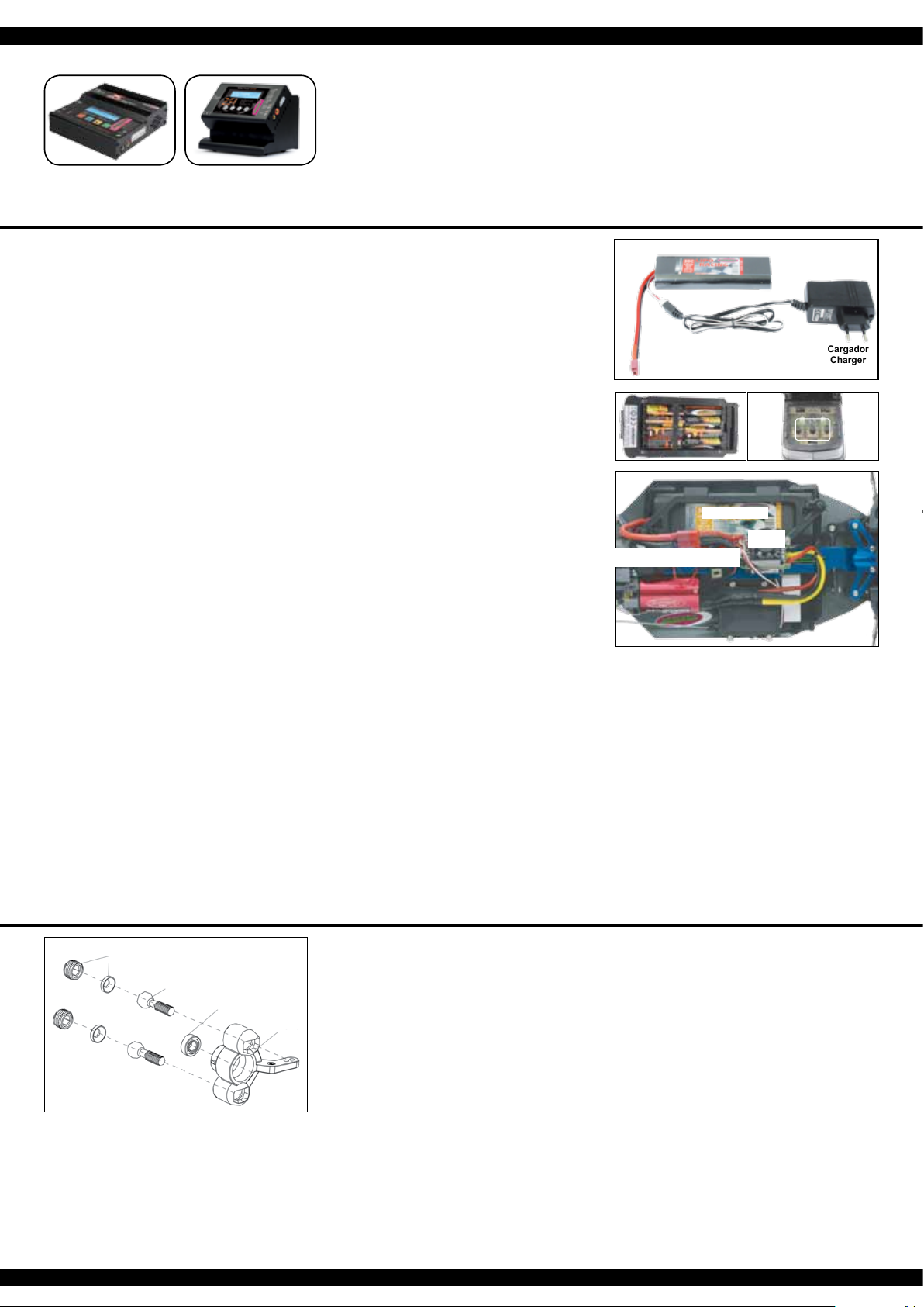
Primero Pasos
Se debe cerciorar que todas las partes del contenido de la caja
estén incluidas. Transmisor, Carro, Cargador, paquete de la ba-
tería.
El paquete de la batería tiene que ser cargado antes de utili-
zarse. Conecte el cargador en un enchufe 230V. Conecte el
cargador a la batería. Si el enchufe del cargador y la batería no
coinciden, entonces usted encontrará un cable de conexión en
su caja. El tiempo de carga promedio de la batería v acía es de
alrededor de 5 - 7 horas.
Coloque 8 partes de baterías AA (doble a) en el transmisor. Si
es batería recargable, por favor cerciórese también de que esté
completamente cargada.
Lea el capítulo para el uso del transmisor y sus controles cuida-
dosamente. Apáguese el radio y cerciórese de todos los botones
del transmisor están en posición neutral. Ahora ponga la batería
en la porta baterías en el vehículo. Asegúrese de que el porta
baterías está asegurado correctamente con los 2 seguros para
el porta baterías incluidos. Ahora conecte la batería al control de
velocidad en el modelo. Mantenga el carro en el aire en caso de
que el controlador (ESC) del motor se encienda a su máxima
potencia. Encienda el control de la velocidad en el interruptor
Encendido / Apagado (On /Off). Fije el modelo en la tierra y
compruébese su funcionamiento apropiado. Dirección derecha/
izquierda, acelerador/freno, hacia adelante y hacia atrás. Si las
ruedas no apuntan hacia adelante aún y cuando el volante de la
transmisión está en neutral, usted puede ajustarlo con el botón
del ajuste la transmisión.
Trimm L/R = derecha/izquierda
Trimm V/R = adelante/atrás
Si las ruedas rotan hacia adelante o hacia atrás, aún y cuando
no se les haya indicado a través de la transmisión, entonces
también el acelerador se necesita ajustar en la transmisión. Le
sugerimos que active ahora la unidad receptora a Prueba de
Fallas en el armado. Cuando se suministra, está desactivado.
Se coloca la palanca del acelerador en posición neutral (véase
el capítulo A Prueba de Fallas). Se presiona el botón a prueba
de fallas en el receptor hasta que encienda/parpadee y se suel-
ta para activarlo. Compruebe este principio en un vehículo
eléctrico solamente con el acelerador en posición neutral,
ya que de otro modo el modelo regresa a la posición previa-
mente programada del acelerador teniendo una pérdida de
la señal del transmisor.
Ahora usted puede hacer la primera prueba de conducción. Si
éste es su primer carro rc, le recomendamos conducirlo en una
pequeña pista de prueba para familiarizarse con el control del
vehículo y los controles del transmisor.
Getting Started
Make sure that all parts from the box content are included. Trans-
mitter, Car, Charger, battery pack.
The battery pack has to be charged before use. Plug the charger
into a 230V outlet. Connect the charger to the battery. If the plug
of the charger and battery do not match, then you will nd a con-
nection lead in your box. The average charging time of the empty
battery is about 5 - 7 hours.
Place 8 pieces of AA batteries into the transmitter. If rechargeba-
le, please also make sure these are fully charged.
Read the chapter for usage of the transmitter and its controls
carefully.
Turn the radio off and make sure all the trim buttons on the trans-
mitter are in neutral position. You have purchased a RTR model,
which means it should be ready for immediate use after charging
all batteries. You need to check the car, electronics and all plastic
parts after each use to make sure no parts are damaged. Also all
the moving parts must be checked for their clearance, bolts and
screws that they are tight. Now put the battery into the battery
holder in the vehicle. Make sure that the battery holder is secu-
red properly with the 2 included clips for the battery holder. Now
connect the battery to the speed control in the model. Keep the
car in the air in case that the motor turns at full power. Switch the
speed control on the On / Off switch. Set the model on the ground
and test it for proper functioning. Steering right/ left, throttle/ bra-
ke, forward and backward. If the wheels do not point straight
forward even though the steering wheel on the transmitter is in
neutral, you can adjust it with the trim button on the transmitter.
Trim L/R = steering
Trim V/R = forward/backward
Should the wheels rotate forward or backward, even though no
command was given through the transmitter, then also the thrott-
le needs to be trimmed on the transmitter.
We encourage you now to activate your receiver‘s built-in Fail-
safe unit. On delivery it is turned off. Leave the throttle lever
in neutral position (see chapter Fail Safe). Press the fail-safe
button on the receiver until it ashes and let go to activate.
Check this principle in an electric vehicle only in the neutral
position of the throttle, because otherwise the model goes
into the previously programmed throttle position in a loss of
the transmitter signal.
Now you can make the rst test drive. If this is your rst rc car, we
recommend to drive it on a small test track to familiarise yourself
with the control of the vehicle and the controls of the transmitter.
ES - Herramientas recomendadas GB - Recommended Tool
No. 15 3055
X-Peak 80 BAL
Cargador
Charger
No. 15 3058
X-Peak 80 BAL Pult
Cargador
Charger
Cargador
Charger
Batería/Battery
ESC/Conector de la Bateria.
ESC/Battery connector
ES
¡Atencion!
Su vehículo tiene un pivote de suspensión delantera. Esto tiene
numerosas ventajas. Es muy resistente y es de fácil manteni-
miento. La conguración (setup) del carro ha sido diseñada para
que el eje motriz no se proyecte hacia afuera. Como con cual-
quier modelo, los tornillos y los pernos se pueden perder durante
una interrupción del carro. Esto puede resultar en una tolerancia
del eje motriz. El eje motriz puede entonces proyectarse hacia
afuera si se ejerciera presión alta. El tornillo interno de la bola
(No. del artículo.: 505081) le permitirá ajustar la tolerancia dando
por resultado los ajustes nos del ancho de la rodada. Para me-
jores resultados al colocar la bola del pivote por primera vez, por
favor ajuste siempre el pivote superior y más bajo de la misma
forma. Apriete tanto como el pivote lo permita y que se pueda
levantar y bajar fácilmente pero no tanto que lo proyecte fuera
si usted le da un ángulo completo a la dirección. El tornillo del
enchufe de plástico (No. del artículo.: 505080) se utiliza sola-
mente para asegurar el nudillo de la dirección. Éste no debe ser
demasiado apretado, de lo contario la dirección no queda suave
y su manejo puede ser afectado negativamente.
GB
Attention!
Your vehicle has a pivot front suspension. This has a number of
advantages. It is very robust and easy to maintain. The set-up of
the car has been done so the drive shaft will not pop out. As with
any model, screws and bolts can losen during break-in of the
car. This can result in tolerance of the drive shaft. The drive shaft
can then pop out if high pressure is applied. The inner ball screw
(item No.: 505081) will enable you to adjust the tolerance resul-
ting in ne adjustments of the track width. For best results when
setting up the pivot ball for the rst time, please always adjust
the upper and lower pivot in the same way. Fasten as far as the
pivot can still be pulled up and down easyly but not as far that it
will pop out if you give full steering angle. The outer plastic socket
screw (item No.: 505080) is only used for securing of the steering
knuckle. This should not be too tight, otherwise the steering is
not smooth and the handling can be adversely affected.
¡Importante!
Con el uso de las baterías de Li-Po, el apagado de baja tensi-
ón del controlador para activar Consulte el manual del con-
trolador. De lo contrario, la batería LiPo puede ser dañado
por una descarga total.
Important!
By using LiPo batteries take care that the undervoltage
shutdown is activated. Otherwise, your LiPo battery can be
damaged by deep discharge.


