manuals.online logo
Brands
  1. Home
  2. •
  3. Brands
  4. •
  5. Jamara
  6. •
  7. Motorized Toy Car
  8. •
  9. Jamara Veloce EP User manual

Jamara Veloce EP User manual

IT - Istruzioni di montaggio
GB - Instruction
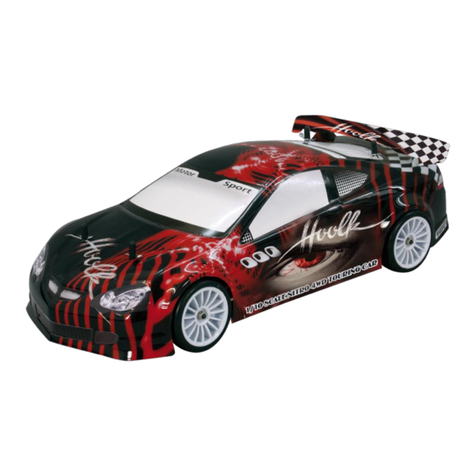
Veloce EP | BL 2,4 GHz
Omologato in: | Permittend in:
EU/CH
IT GB
LED
3
15
05
3
0
2
5
10
25
30
35
20
Km/h
uber/
over
5
35
35
35
35
3
15
0
5
3
0
2
5
10
25
30
35
20
Km/
Km/
h
Km/h
Km/
uber/
uber/
uber/
uber/
uber/
uber/
ov
ov
er
over
ov
35
35
35
35
No. 05 3370
K
m/h
K
K
m
K
m
m
K
m
K
m
K
m
K
m
/h
m/h
m
m/h
m
/h
/h
m/h
m
/h
60
No. 05 3372
3
15
00
4
0
2
5
10
25
30
40
20
Km/h
uber/
over
0
40
40
40
40
3
15
0
0
4
0
2
5
10
25
30
40
20
Km/
Km/
h
Km/hKm/
uber/
uber/
uber/
uber/
uber/
uber/
ov
ov
er
overov
40
40
40
40
No. 05 3371
Cod. | Ord. No.
05 3370 Veloce EP 2,4 GHz
05 3371 Veloce EP LiPo 2,4 GHz
05 3372 Veloce BL LiPo 2,4 GHz
2
IT - Sommario
Istruzioni per la sicurezza 2
Allgemeine Hinweise 4
Dichiarazione di conformita’ 4
Disposizioni p. l‘eliminazione nel Rispetto dell‘ ambiente 4
Contenuto del kit | Dati tecnici | Highlights 4
Attrezzi consigliati 6
Primi passi 7/9
Trasmittente CCX Car 2,4 GHz 11 - 16
Regolatore 17 - 28
Informazioni sull’uso degli accumulatori 29/31
Risoluzione dei problemi 33
Montaggio 34 - 37
Impostazione dell’assetto/sospensione 39 - 40
Punti impostazione 41 - 43
Pezzi di ricambio 44 - 47
Pezzi Tuning e accessori 47/48
Ruote e cerchi 49
Luci di segnalazione a LED Car 50
Capacità diagramma 51
Centri di Assistenza 52
Istruzioni per la sicurezza
Questo modello non e‘ un giocattolo!
Consigliato per persone superiori ai 14 anni!
Attenzione: Non adattato ai bambini inferioti ai 36 mesi.
Pericolo di affogamento.
Contiene pezzi piccoli.
ATTENZIONE!
• Vi preghiamo di leggere attentamente le istruzioni prima di
usare il modello. Sollevare la scatola e istruzioni!
Istruzione di sicurezza per l’uso
• Este dispositivo no debe ser utilizado por personas(incluidos
niños) con discapacidad física,habilidades sensoriales o
mentales o la falta de experiencia y / o conocimientos, porque
son responsables de su propia seguridad persona de
supervisión sobre cómo se utiliza el dispositivo.
O la persona que son supervisados en cómo usar.
• Mantenga el modelo lejos de los niños, por lo que el modelo
no es adecuado (ver nota en edad).
• I modelli volanti radiocomandati non sono giocattoli, per cui
devono essere usati da persone responsabili in grado di
intendere.
• Seguite attentamente le istruzioni per ottenere un modello
afdabile, ricordando che voi sarete i responsabili per la
costruzione ed il successivo uso.
• Nel montaggio vengono usate attrezzi e coltello. Siete pregati
di lavorare con la massima prudenza.
• In caso di uso di colle e colori (non compresi nella scatola),
osservare il manuale fornito.
• Tenete sempre queste istruzioni a portata di mano per
eventuali consultazioni anche una volta nita la costruzione
• Tenete sempre queste istruzioni a portata di mano per
eventuali consultazioni anche una volta nita la costruzione
• Tenete mani, capelli e parti svolazzanti lontane da parti
rotabili.
• Tenetevi sempre lontani dalle parti rotanti..
• Evitate di volare con vento forte, pioggia o temporale,attenti
alle scariche elettriche temporalesche sull‘ antenna della
vostra radio!
• Non usate il modello nelle vicinanze di stazione radio, linea
di alta tensione, casse di trasformazione oppure simile. Quete
installazioni causano disturbi frequenza che portano alla perd -
ita del controllo  no alla perdita del modello.
• Sempre in aree libere legalmente autorizzate, lontane da altri
ostacoli.
• Controllare che nessun altro usi la stessa frequenza, per
evitare danni sul modello, persone e oggetti.
• Ogni modica alle parti di un kit ne annulleranno la garanzia.
• Non esponete il modello o le batterie a lungo ai raggi solari
meglio tenerli all‘ ombra.
Istruzioni generali di sicurezza
• Ogni kit contiene piccoli pezzi che potrebbero essere
inghiottiti da bambini, per cui vi consigliamo di tenere lontani i
bambini durante il montaggio di un modello.
• Evitare l’uso del modello nei posti affollati e nella vicinanza di
bambini. Mai usare il modello su luoghi e stradi pubblichi.
• Non usare mai il modello su un area bagnata / umida. Rischio
di danneggiare la parte elettronica. In caso che il modello
abbia preso umidità, assicurarsi che tutto si asciuga bene per
garantire il funzionamento.
• I principianti dovranno farsi assistere da un modellista esperto
ed é bene anche che si associno ed un gruppo modellistico
che li coprirà con una polizza assicurativa oltre che con l‘ aiuto
di piloti esperti.
• Controllare regolarmente il modello, la trasmittente e il cavo di
carica su danneggiamenti. Non usare la parte danneggiata
nche non sia rimessa in ordine. Per i danni derivanti
dall‘attività operativa creato un modello dei titolari devono
aderire.
• Ricordate che il vostro medello é costruito con materiali
inammabili, perciò tenetelo lontano da amme libere .
• Accendete sempre prima la trasmittente e poi la ricevente,
mentre per lo spegnimento usate la procedura inversa.
• Quando accendete la vostra radio, assicuratevi SEMPRE che
lo stick del gas sia al minimo.
Informazioni importanti per l’uso
di batterie a pacchi ricaricabili
• Badare la polarità delle batterie e il modo d’inserimento.
• Non caricare mai batterie non ricaricabili.
• Togliere il pacco batteria del modello per caricarlo (per quanto
previsto)
• Caricare il pacco batteria sempre sotto sorveglianza di adulti.
• Non usare mai batterie di tipi diversi, oppure batterie nuove
con quelle usate.
• Inserire le batterie facendo attenzione alla polarità.
• Togliere il pacco batteria scarico dal modello.
• Evitare in ogni caso il contatto dei contatti (coro circuito).
• Il pacco batteria fornito non è caricato. Prima dell’uso,
caricatelo.
• Non caricare il pacco batteria subito dopo l’uso del modello.
Fare raffreddare il pacco batteria prima della carica.
• Evitare il corto circuito! Questo potrebbe causare un
inammazione e di sicuro accorciano la vita del pacco
batteria.
• Usare solo il caricatore fornito per la ricarica.
• Tenere lontano le batterie e pacchi ricaricabili dai bambini.
Istruzioni per la carica dei pacchi ricaricabili
• Collegare il pacco batteria con il cavo caricatore.
• Collegare la presa del caricatore alla corrente.
• Caricare la batteria no che e completamente carica!
• Una volta terminata la carica, togliere la presa dalla corrente e
disconnettere il pacco batteria dal cavo caricatore. Il pacco
batteria è pronto per l’uso.
3
GB - Content
Safety Information 3
General Information 5
Certicate of Conformity 5
Disposal information 5
Box contents | Technical data | Highlights 5
Recommended Tool 6
Getting Started 8/10
Transmitter CCX Car 2,4 GHz 11 - 16
Controller 17 - 28
Instructions for the use of Batteries 30/32
Troubleshooting 33
Assembly 34 - 37
Suspension Settings 39 - 40
Setting points 41 - 43
Spare parts 44 - 47
Tuning parts and accessories 47/48
Tyres and rims 49
LED lights 50
Power diagram 51
Service centre 52
Safety Information
This radio control model is not a toy!
Suitable for persons over 14 years!
Note: Not suitable for children under 36 months.
Risk of suffocation.
Contains small parts which can be swallowed.
WARNING!
• Read the instructions carefully before using the model.
Keep the instructions and packing after reading it.
Operating Safety Instructions
• This device is not intended for use by individuals (Including
children) with reduced physical sensory, mental abilities, lack
of experience and / or knowledge, unless they are supervised
in how the device is to be used.
• Keep the model away from Children in case it is not
appropriate to be used by a Child (see note of age).
• Read carefully and fully understand the instructions before
commencing assembly.
• Take enough safety precautions prior to operating this model.
You are responsible for this model’s assembly and safe
operation!
• When assembling this kit, tools including knives are used.
Extra care should be taken to aviod personal injury.
• Read and follow the instructions supplied with paints and/or
Qcement, if used (not included).
• Always keep this instruction manual ready at hand for quick
reference, even after completing the assembly.
• Keep hands, hair and loose clothing away from rotating and
heated parts.
• Never allow anything to come into contact with rotating parts.
• The model can only be moved in good weather. Do not run in
wind, rain or thunder storms.
• Find a place to y which complies with any laws, and is free
from obstacles.
• Do not operate your model near radio stations, power lines,
transformer boxes or similar facilities! This can result in radio
interference, causing loss of control over the model.
• Make sure that no one else is using the same frequency in
your running area. Using the same frequency at the same
time can cause seriou accidents, whether it’s driving.
• The model should not be changed in any way, doing so will
invalidate the guarantee.
• Do not expose the model or batteries to direct sunlight, always
keep them in the shade.
General Safety Instructions
• Assemble this kit only in places out of children’s reach! The kit
contains small parts which may cause choking if swallowed,
keep away from small children.
• NEVER y your model over people and never operate the
model in way which may endanger people, small children or
animals.
• Never operate the model on rain or over damp surfaces, this
may damage the electronics. If R/C unit, motor, or battery get
wet, clean and dry thoroughly in a dry shaded area.
• If this model is the rst radio controlled model which you are
attempting to build or run, you should secure the assistance of
an experienced model pilot. Your local dealer will be able to
assist you in locating your local model model sport club or
experienced pilots in your area.
• Inspect the model before and after every drive for damage
and loosing screws and plug connections. The operator is
responsible for any damage caused by the operation of ying
models.
• Remember that your model is made from such materials as
plastic and rubber and as such is inammable. Keep it away
from any open ame, or high temperatures.
• When operating the model, switch on the transmitter rst and
then the model, switch off in the reverse order.
• Always ensure that the throttle stick is in the low position
before you switch on.
Important Information for use of batteries and battery packs
• Adhere to the specication of how the batteries should be
taken out or placed into the product.
• Do not recharge disposable batteries!
• Rechargeable batteries should be taken out of the model
before charging (if applicable)!
• Only charge rechargeable batteries under adult supervision!
• Different types of batteries or new and used batteries should
not be used together!
• Adhere to correct polarity!
• Remove spent batteries from the device!
• Do not short circuit connection terminals!
• The included battery is not charged! Charge before use!
• Do not charge the battery pack immediately after use! If the
battery pack becomes warm during use, leave it to cool down
before charging!
• Avoid short circuits! This could in the worst case cause res
and in any case it will reduce the battery life.
• Only recharge battery packs with same capacity and
specications as the supplied battery pack if you intend to use
the supplied charger.
• Keep batteries away from small children!
Information on how to charge the battery pack
• Connect the battery to the charger.
• Plug the charger into the socket.
• Once fully charged, unplug the charger from the wall socket
and disconnect the battery from the charger! The battery is
now ready to use!
Dati tecnici
Misure ~ 420 x 320 x 200 mm
Peso ~ 2000 g
Servi 1 x 4,5 kg
Batteria LiPo
NiMh
7,4 V 3700 mAh
7,2 V 2000 mAh
Motor EP
BL
Venti 540, 270 W
3650, 420 W 3200 KV
Angaben ohne Gewähr.
Irrtum und technische Änderungen
vorbehalten.
Highlights
BL Version
• Motore Brushless Red Power 3200 KV
• Regolatore Brushless 60 A
programmabile, con ventola
EP Version
• Motore a spazzole 540
• Regolatore impermeabile, idoneo per
LiPo 40 A
BL & EP Version
• Pivot-Ball anteriore
• Chassis in alluminio design carbonio
• Assetto regolabile
• Sterzo servo straiato
• Ammortizzatori regolabili
• Cardani in acciaio
• Piastra Radio e coperchio
ammortizzatori in alluminio
• 2 Fari LED (con 8 singole LED potenti)
• Trasmissione protetta
• Ricevente protetta d’acqua
Contenuto del kit 05 3270
• Modello 4WD
• Trasmittente 2,4 GHz
• Batteria NiMh
• Caricatore 230 V
• Motore elettrico montato
• Regolatore elettrico montato
• 1 servo montato
• Carrozzeria verniciata
• Decals
• Istruzioni con pezzi Tuning
Contenuto del kit 05 3271
• Modello 4WD
• Trasmittente 2,4 GHz
• Batteria Lipo
• Caricatore 230 V con Balancer integrato
• Motore elettrico montato
• Regolatore elettrico montato
• 1 servo montato
• Carrozzeria verniciata
• Decals
• Istruzioni con pezzi Tuning
Contenuto del kit 05 3272
• Modello 4WD
• Trasmittente 2,4 GHz
• Batteria Lipo
• Caricatore 230 V con Balancer integrato
• Motore brushless montato
• Regolatore brushless montato
• 1 servo montato
• Carrozzeria verniciata
• Decals
• Istruzioni con pezzi Tuning
4
IT - Informazioni generali
Jamara e. K. non e´responsabile per danni, sostenute al prodotto
stesso o attraverso questo, dovuti ad una gestione non corretta
del articolo. Solo il cliente si assume la piena responsabilità per
la manutenzione e l´utilizzo corretto dello stesso; questo include
il montaggio, la ricarica, l´utilizzo,  no alla scelta della aerea di
applicazione. Si prega di notare e rispettare le istruzioni d´uso,
questi contengono informazioni e avvertimenti molto importanti.
Attenzione!
Accensione: accendete prima il trasmettitore e poi il
modellino.
Spegnimento: spegnere prima il modellino e poi il
trasmettitore.
Dichiarazione di conformita‘
Jamara e. K. dichiara qui di seguito che il modello‚ „Veloce EP
053370; Veloce EP LiPo 053371; Veloce BL LiPo 053372“ segue
le direttive CEE menzionate più sotto ed in particolare che il mo-
dello é stato costruito seguendo queste direttive.
Potrete chiedere ogni altro chiarimento in merito a:
Jamara e.K. | Manuel Natterer
Am Lauerbühl 5 | D-88317 Aichstetten
Tel. +49 (0) 7565/9412-0 | Fax +49 (0) 7565/9412-23
www.jamara.com | [email protected]
Piu informazioni:
www.neuershop.jamara.com/Conformita
Testi della direttiva europea:
- (R&TTE) Apparecchiature terminali Telecom e Radio
1999/5/CE
- (WEEE) apparecchi élettronici 2002/96/CE
- (RoHS) Proibizione d‘uso di certi prodotti chimici pericolosi
per la costruzione di componenti elettronici e per la
produzione di materiale elettronico 2011/65/EU
Disposizioni per l‘eliminazione nel Rispetto
dell‘ ambiente
Non disperdete le batterie nell‘ ambiente ma gettatele,
una volta scaricate, negli appositi contenitori. Posso-
no considerarsi scariche quando il motore smette di
girare. Se dovete eliminare dei componenti elettronici,
eliminateli. Nelle apposite discariche.
Importante per pezzi elettronici Smaltire i pezzi elett-
ronici secondo le norme di legge (Radio/Caricatore/
Modello ecc.) . Gettari questi articoli solo negli conte-
nitori appositi.
GB - General Information
Jamara e.K. is not liable for any damage caused to the product
itself or through this, provided this is due to improper operation or
handling errors. The Customer alone bears the full responsibility
for the proper use and handling, including without limitation, the
assembly, the charging process, the use and choice of the ope-
ration area. Please refer to the operating and user instructions, it
contains important information and warnings.
Attention!
Switch the transmitter on  rst then the model. When you
are  nisished  rst switch off the model then the transmitter.
Disposal information
Please care for a environmental correct and legal way
of disposing the batteries and/or accus. Please, only
throw away empty accus into the collect-boxes in your
local shops or commune. (Normally discharge the ac-
cus, when the model stops running)
All parts of this model should be disposed of correctly,
in particular electronic components may be subject to
local restrictions. Your dealer will advise you.
GB - Technical data
Dimensions ~ 420 x 320 x 200 mm
Weight ~ 2000 g
Servos 1 x 4,5 kg
Battery LiPo
NiMh
7,4 V 3700 mAh
7,2 V 2000 mAh
Motor EP
BL
Venti 540, 270 W
3650, 420 W 3200 KV
No responsibility is taken for the correct-
ness of this information. Subject to change
without prior notice.
Errors and omissions excepted.
GB - Highlights
BL Version
• Red Power 3200 KV Brushless Motor
• Speedcontroller Brushless 60 A full
programmable and activ cooled
EP Version
• Powerful 540 motor
• Waterproof lipo capable speed cont
roller 40 A
BL & EP Version
• Pivot-Ball System front
• Alu Chassis Carbon Design
• Adjustable suspension
• Horizontal stearing servo
• Adjustable oil pressure shocks
• Steel drivingshaft
• Alu Radio plate & shock cap
• Two LED headlights with
8 bright LED‘s
• Dirt resistant gear-box
• Water resistant receiver-box
5
Box contents 05 3370
• 4WD model
• Transmitter 2,4 GHz
• Battery pack NiMh
• Charger 230 V
• Electric motor installed
• Electric controller installed
• 1 servo installed
• Painted body
• Decal
• Instruction with Tuning parts
Box contents 05 3371
• 4WD model
• Transmitter 2,4 GHz
• Battery pack LiPo
• Charger 230 V with integrated
balancer
• Electric motor installed
• Electric controller installed
• 1 servo installed
• Painted body
• Decal
• Instruction with Tuning parts
Box contents 05 3372
• 4WD model
• Transmitter 2,4 GHz
• Battery pack
• Charger 230 V with integrated
balancer
• Brushless motor installed
• Brushless controller installed
• 1 servo installed
• Painted body
• Decal
• Instruction with Tuning parts
Conformity
JAMARA e. K. hereby declare that the model‚ „Veloce EP 053370;
Veloce EP LiPo 053371; Veloce BL LiPo 053372“ follows the ap-
propriate and relevant EEC Directives, in particular those listed
below and that the model has been constructed accordingly. Set
contains transmitter and receiver.
Please direct any queries that you may have regarding conformi-
ty to our service department at:Jamara e.K. | Manuel Natterer
Am Lauerbühl 5 | D-88317 Aichstetten
Tel. +49 (0) 7565/9412-0 | Fax +49 (0) 7565/9412-23
www.jamara.com | [email protected]
Further information can also be found at:
www.neuershop.jamara.com/Conformity
Relevant EC Directives:
- Radio & Telecom Terminal Equipment (R&TTE) 1999/5/EC
- Waste Electrical and Electronic Equipment (WEEE)
2002/96/EC
- Restriction of Hazardous Substances (RoHS) 2011/65/EU
66
IT - Attrezzi consigliati GB - Recommended Tool
6
+-
+
+
-
No. 28 1785
Alesatore conico per carroz.
Hub drill for bodywork
Set cacciaviti, punta croce
Philips Screwdrivers
No. 19 0073
Set cacciaviti, punta piatto
Flat Screwdrivers
No. 19 3065
1,5/2,0/2,5/3,0mm
Chiavi per vite ad esagono
Hexagonal head wrench set
Forbici per Lexcarrozzeria
Lexan scissors
No. 19 0065
Misuratore convergenza
Camber adjusting Tool
No. 19 0060
Mesura distanziatore altezza
Height lange
No. 23 2060
Power Tape silicone
Doublesided power tape
No. 23 0409 20 g
„Wheel blood“
Colla per gomme
Rim Glue
No. 28 1904 Louise
Olio ammortizzatore silicone
Shock-Oil
No. 23 2423 medium
Lacca protezione
Nut lock
No. 23 0461 400 ml
Schiuma speciale Spray
Special cleaning foam
No. 15 3065
X-Peak 90 Touch
Caricatore
Charger
No. 50 5401 piccoli/small
Graffette per carrozzeria
Body clips
No. 15 3055
X-Peak 80 BAL
Caricatore
Charger
No. 19 3130
Banco montaggio Car Stand
Car Stand rotatable
No. 15 2058
X-Peak 50 BAL Pult
Caricatore
Charger
No. 15 2060
X-Peak 50 BAL
Caricatore
Charger
No. 05 9273 1:10
Graffette per carrozzeria
Body clips
IT - Primi passi
Assicurarsi che tutte le parti indicati sono incluse nella confezi-
one di scatola. Trasmittente, modello, caricabatterie e batterie.
Per primo bisogna caricare la batteria. Collegare il caricabatterie
ad una presa 230V. Collegare il caricabatterie alla batteria del
veicolo. In certi casi utilizzare il cavo adattatore fornito per col-
legare la batteria con il caricatore. Il tempo medio di carica della
batteria è di circa 6 - 8 ore (LiPo 5 - 7 ore).
Inserire 8 batterie AA oppure 8 bat-
terie ricaricabili AA nella trasmittente.
In caso del utilizzo di batterie ricari-
cabile, è necessario caricare questi
con un caricatore separato.
Leggere il capitolo sulla trasmittente.
Accendere la trasmittente e assicurarsi
che i trim siano in posizione neutrale.
Avete acquistato un modello RTR. Vale
a dire, che il modello è preimpostato
per la maggior parte per l‘uso immedia-
to. Tuttavia, è essenziale prima e dopo
ogni utilizzo, di controllare il funziona-
mento della parte meccanica ed elett-
ronica.
Si consiglia di control-
lare anche tutte le parti
in movimento del mo-
dello. Mettete la batteria
nel vano della batteria, a
bordo del veicolo. Fare at-
tenzione che la batteria sia
correttamente  ssata con i
2 clip in dotazione e che la
batteria non abbia un gioco
eccessivo nel vano appropriato. Ora collegare la batteria con il
regolatore di velocità. Tenere il modello in aria per il caso che il
motore si metta a girare a tutto gas. Ora accendere il regolatore
di velocità tramite l`interruttore ON / OFF. Posizionare il modello
sul pavimento e veri carne il corretto funzionamento testando lo
sterzo (sinistra/destra) ed il gas (avanti/indietro) Se le ruote non
puntano dritti in avanti, anche se il volante della trasmettente è
in posizione neutrale, è possibile ottenere aiuto con il trim della
trasmittente nella posizione corretta.
Trim L/R = Sterzo
Trim V/R = Avanti / Indietro
Se le ruote girano in avanti o indietro, anche se nessun comando
è stato dato attraverso il trasmettitore, poi anche l‘acceleratore
deve essere tagliato sul trasmettitore. Vi incoraggio ad attivare il
ricevitore integrato in unità fail-safe. Al momento della conseg-
na è spento
Se le ruote girano in avanti o indietro, senza toccare lo stick del
gas, è necessario impostare il trim del gas nella giusta posizione.
Consigliamo di attivare il Fail Safe, integrato nel regolatore di
velocità. Il Fail Safe è disattivato in stato di consegna del prodotto.
Per attivare il Fail Safe, leggere attentamente il capitolo
Fail Safe.Attivazione Fail Safe: Accertarsi che lo stick del
gas sia in posizione neutrale. Premere il tasto Fail Safe sulla
ricevente  nche lampeggia il LED. Dopo il lampeggiamento
del LED, lasciare il pulsante.
Ora si può fare la prima unità di prova. Se questa è la tua prima
auto rc, si consiglia di guidare su una pista piccola per familia-
rizzare con il controllo del veicolo e i comandi del trasmettitore.
Attenzione!
Il veicolo è dotato di una Pivot sospensione anteriore. Questa
ha una serie di vantaggi. E ‚molto robusta e la manutenzione
e´molto facile. Questo è impostato in fabbrica in modo che la
carreggiata non permette agli cardani di saltare fuori. Come con
qualsiasi modello, dopo l´inizio dell’uso si rallentano di qualche
millimetro sia la sospensione sia i bulloni. Questo gioco minimo,
po’ abbastare sotto massimo sforzo per fare saltare fuori i carda-
ni. Pertanto è necessario per assicurarsi prima di ogni uso che
tutte le viti, dadi, giochi ecc., sono  ssate correttamente.
La vita esterna in plastica 505080 serva per  ssare il fuso a
snodo sulla vite a sfera. Questo non deve essere serrata troppo
forte. In caso contrario, lo sterzo non si muove liberamente e la
guida può essere in uenzata negativamente.
77
ON/OFF
L/R V/R
Trim
50 5080
50 5081
07 9996
50 5079
Version No. 053270 & 053271
Caricatore
Batteria
Cavo di ridu-
zione
Caricatore
Batteria
Vers. 053270 Vers. 053271
Le immagini possono essere diversi
7
Version EP No. 053270 & 053271
Regolatore
On/Off
Batteria
Modo LiPo
On/Off
88
GB - Getting Started
Make sure that all parts from the box content are included. Trans-
mitter, Car, Charger, battery pack.
The battery pack has to be charged before use. Plug the charger
into a 230V outlet. Connect the charger to the battery. If the plug
of the charger and battery do not match, then you will  nd a con-
nection lead in your box. The average charging time of the empty
battery is about 6-8 hours.
Place 8 pieces of AA batteries into
the transmitter. If rechargebale, ple-
ase also make sure these are fully
charged.
Read the chapter for usage of the
transmitter and its controls carefully.
Turn the radio off and make sure all the
trim buttons on the transmitter are in
neutral position.
You have purchased a RTR model,
which means it should be ready for im-
mediate use after charging all batteries.
You need to check the car, electronics
and all plastic parts after each use to
make sure no parts are damaged. Also
all the moving parts must be checked
for their clearance, bolts and screws that they are tight.
Now put the battery into the
battery holder in the vehic-
le. Make sure that the batte-
ry holder is secured proper-
ly with the 2 included clips
for the battery holder. Now
connect the battery to the
speed control in the model.
Keep the car in the air in
case that the motor turns at
full power.
Switch the speed control on the On / Off switch. Set the model on
the ground and test it for proper functioning. Steering right/ left,
throttle/ brake, forward and backward. If the wheels do not point
straight forward even though the steering wheel on the trans-
mitter is in neutral, you can adjust it with the trim button on the
transmitter.
Trim L/R = steering
Trim V/R = forward/backward
Should the wheels rotate forward or backward, even though no
command was given through the transmitter, then also the thrott-
le needs to be trimmed on the transmitter.
We encourage you now to activate your receiver‘s built-in Fail-
safe unit. On delivery it is turned off.
Leave the throttle lever in neutral position (see chap-
ter Fail Safe). Press the fail-safe button on the re-
ceiver until it  ashes and let go to activate.
Check this principle in an electric vehicle only in the neutral
position of the throttle, because otherwise the model goes
into the previously programmed throttle position in a loss of
the transmitter signal.
Now you can make the  rst test drive. If this is your  rst rc car, we
recommend to drive it on a small test track to familiarise yourself
with the control of the vehicle and the controls of the transmitter.
Attention!
Your vehicle has a pivot front suspension. This has a number of
advantages. It is very robust and easy to maintain. The set-up of
the car has been done so the drive shaft will not pop out. As with
any model, screws and bolts can losen during break-in of the car.
This can result in tolerance of the drive shaft. The drive shaft can
then pop out if high pressure is applied.
The inner ball screw (item No.: 505081) will enable you to adjust
the tolerance resulting in  ne adjustments of the track width. For
best results when setting up the pivot ball for the  rst time, please
always adjust the upper and lower pivot in the same way. Fasten
as far as the pivot can still be pulled up and down easyly but not
as far that it will pop out if you give full steering angle. The outer
plastic socket screw (item No.: 505080) is only used for securing
of the steering knuckle. This should not be too tight, otherwise
the steering is not smooth and the handling can be adversely
affected.
On/Off
L/R F/B
Trim 50 5080
50 5081
07 9996
50 5079
ESC
On/OFF
Battery
Lipomode
ON/OFF
Charger
Battery
Charging
adapter
Charger
Battery
Vers. 053270 Vers. 053271
Version EP No. 053270 & 053271
Illustration can be different
99
IT - Primi passi
Assicurarsi che tutte le parti indicati sono incluse nella confe-
zionedi scatola. Trasmittente, modello, caricabatterie e batterie.
Per primo bisogna caricare
la batteria. Collegare il ca-
ricabatterie ad una presa
230V. Collegare il carica-
batterie alla batteria del vei-
colo. In certi casi utilizzare il
cavo adattatore fornito per
collegare la batteria con il
caricatore. Il tempo medio
di carica della batteria è di
circa 5 - 7 ore.
Inserire 8 batterie AA oppure 8 bat-
terie ricaricabili AA nella trasmittente.
In caso del utilizzo di batterie ricari-
cabile, è necessario caricare questi
con un caricatore separato.
Leggere il capitolo sulla trasmittente.
Accendere la trasmittente e assicurarsi
che i trim siano in posizione neutrale.
Avete acquistato un modello RTR. Vale
a dire, che il modello è preimpostato
per la maggior parte per l‘uso immedia-
to. Tuttavia, è essenziale prima e dopo
ogni utilizzo, di controllare il funziona-
mento della parte meccanica ed elett-
ronica. Si consiglia di controllare
anche tutte le parti in movimento del
modello.
Mettete la batteria nel vano della batteria, a bordo del veicolo.
Fare attenzione che la batteria sia correttamente  ssata con i
2 clip in dotazione e che
la batteria non abbia un
gioco eccessivo nel vano
appropriato. Ora collegare
la batteria con il regolatore
di velocità.
Tenere il modello in aria per
il caso che il motore si met-
ta a girare a tutto gas.
Ora accendere il rego-
latore di velocità tramite
l`interruttore ON / OFF. Posizionare il modello sul pavimento e
veri carne il corretto funzionamento testando lo sterzo (sinistra/
destra) ed il gas (avanti/indietro) Se le ruote non puntano dritti
in avanti, anche se il volante della trasmettente è in posizione
neutrale, è possibile ottenere aiuto con il trim della trasmittente
nella posizione corretta.
Trim L/R = Sterzo
Trim V/R = Avanti / Indietro
Se le ruote girano in avanti o indietro, anche se nessun comando
è stato dato attraverso il trasmettitore, poi anche l‘acceleratore
deve essere tagliato sul trasmettitore. Vi incoraggio ad attivare il
ricevitore integrato in unità fail-safe. Al momento della conseg-
na è spento.
Se le ruote girano in avanti o indietro, senza toccare lo stick del
gas, è necessario impostare il trim del gas nella giusta posizione.
Consigliamo di attivare il Fail Safe, integrato nel regolatore di ve-
locità. Il Fail Safe è disattivato in stato di consegna del prodotto.
Per attivare il Fail Safe, leggere attentamente il capitolo Fail
Safe. Attivazione Fail Safe: Accertarsi che lo stick del gas
sia in posizione neutrale. Premere il tasto Fail Safe sulla ri-
cevente  nche lampeggia il LED. Dopo il lampeggiamento
del LED, lasciare il pulsante.
Ora si può fare la prima unità di prova. Se questa è la tua prima
auto rc, si consiglia di guidare su una pista piccola per familia-
rizzare con il controllo del veicolo e i comandi del trasmettitore
Importante:
Attivare il Fail Safe solo se i stick della Radio siano in posizione
neutrale (in caso di una macchina elettrica), altrimenti il modello
reagisce alla posizione dello stick precedentemente programma-
to, in questo caso si rischia la perdita del modello. Ora è possibile
effettuare la prima guida di prova. Se questo modello è la vostra
prima auto RC, si consiglia di guidare il modello su una pista pic-
cola per conoscere il comportamento della macchina ai comandi
della radio.
Importante!
Utilizzando batterie LiPo fare in modo che l‘arresto sottotensione
è attivato, vedere a pagina 20-23
In caso contrario, la batteria LiPo possono essere danneggiati
da scariche profonde. Si consiglia di un cut-off di tensione di 3
V per cella
Caricatore
Batteria
ON/OFF
L/R V/R
Trim
50 5080
50 5081
07 9996
50 5079
Version BL No. 053372
Le immagini possono essere diversi
Regolatore
ON/OFF
Batteria
Regolatore/batteria
collegamento
1010
GB - Getting Started
Make sure that all parts from the box content are included. Trans-
mitter, Car, Charger, Balancer, battery pack.
The battery pack has to be
charged before use. Plug the
charger into a 230V outlet.
Connect the charger to the
balancer and the balancer to
the balancer plug of the bat-
tery The average charging
time of the empty battery is
about 5 - 7 hours.
Place 8 pieces of AA batteries into the
transmitter. If rechargebale, please
also make sure these are fully charged.
Read the chapter for usage of the
transmitter and its controls carefully.
Turn the radio off and make sure all the
trim buttons on the transmitter are in
neutral position.
You have purchased a RTR model, which
means it should be ready for immedia-
te use after charging all batteries. You
need to check the car, electronics and
all plastic parts after each use to make
sure no parts are damaged. Also all the
moving parts must be checked for their clearance, bolts and
screws that they are tight.
Now put the battery into the
battery holder in the vehicle.
Make sure that the battery
holder is secured properly with
the 2 included clips for the
battery holder. Now connect
the battery to the speed con-
trol in the model.
Keep the car in the air in case
that the motor turns at full po-
wer.
Switch the speed control on the On / Off switch. Set the model on
the ground and test it for proper functioning. Steering right/ left,
throttle/ brake, forward and backward. If the wheels do not point
straight forward even though the steering wheel on the transmitter
is in neutral, you can adjust it with the trim button on the trans-
mitter.
Trim L/R = steering
Trim V/R = forward/backward
Should the wheels rotate forward or backward, even though no
command was given through the transmitter, then also the throttle
needs to be trimmed on the transmitter.
We encourage you now to activate your receiver‘s built-in Failsafe
unit. On delivery it is turned off.
Leave the throttle lever in neutral position (see chapter Fail Safe). Press
thefail-safebutton onthereceiveruntilitflashesand let gotoactivate.
Check this principle in an electric vehicle only in the neutral
position of the throttle, because otherwise the model goes
into the previously programmed throttle position in a loss of
the transmitter signal.
Now you can make the first test drive. If this is your first rc car, we
recommend to drive it on a small test track to familiarise yourself
with the control of the vehicle and the controls of the transmitter.
Attention!
Your vehicle has a pivot front suspension. This has a number of
advantages. It is very robust and easy to maintain. The set-up of the
car has been done so the drive shaft will not pop out. As with any
model, screws and bolts can losen during break-in of the car. This
can result in tolerance of the drive shaft. The drive shaft can then
pop out if high pressure is applied.
The inner ball screw (item No.: 505081) will enable you to adjust
the tolerance resulting in fine adjustments of the track width. For
best results when setting up the pivot ball for the first time, please
always adjust the upper and lower pivot in the same way. Fasten
as far as the pivot can still be pulled up and down easyly but not
as far that it will pop out if you give full steering angle. The outer
plastic socket screw (item No.: 505080) is only used for securing of
the steering knuckle. This should not be too tight, otherwise the
steering is not smooth and the handling can be adversely affected.
Important!
By using LiPo batteries take care that the undervoltage shutdown
is activated, see page 20 - 23
Otherwise, your LiPo battery can be damaged by deep discharge.
We recommend a cut-off voltage of 3 V per cell
Version BL No. 053372
ESC
On/Off
Battery
ESC/Battery
Connector
On/Off
L/R F/B
Trim
50 5080
50 5081
07 9996
50 5079
Charger
Battery
Illustration can be different
1111
IT - Trasmittente CCX Car 2,4 GHz
Contenuto
Il sistema di trasmissione CCX 2,4 GHz Car ,
è composto dalla trasmittente a due canali,
dalla ricevente a tre canali ed dal manuale
delle istruzioni.
GB - Transmitter CCX Car 2,4 GHz
Box contents
Our Radio Control System CCX 2.4 GHz Car
comes complete with transmitter, matching 3
channel receiver and these instructions.
Accessori consigliati
Per il funzionamento di un modello radiocomandato sono neces-
sari servi adeguati, una batteria per la ricevente, un interruttore e
il suo cavo di ricarica. Per un modello ad alimentazione elettrica,
è altresì necessario un regolatore che, nella maggior parte dei
casi, fornisce la tensione di alimentazione della ricevente. Per il
funzionamento, la trasmittente necessita di otto batterie mignon
AA o accumulatori. Per l‘utilizzo di accumulatori è necessario
avere anche un carica batterie.
Usare solo prodotti di alta qualità, come abbiamo nel nostro as-
sortimento. Consultate il nostro catalogo aggiornato oppure in
Internet (www.jamara.com).
Caricatore Universal Cod. 15 0004
Cavo interrutore Cod. 09 8254
Batterie 8 x Mignon 1,5V Cod. 14 0095
o
Batterie 8 x Mignon 2600mAh 1,2V Cod. 14 1016
Recommended Accessories
In order to operate a Radio Controlled model you will require
servos
which are suitable for the model, a receiver battery and a switch
cable. For an electric model you will also require an Electronic
Speed
Controller which will in most cases also provide power to the re-
ceiver. To power the transmitter you will need 8 X Mignon (AA)
sized dry or rechargeable batteries. If you choose to use rechar-
geable batteries you will also require a suitable charger.
You should only use high-quality accessories with this system
such as those found in our product catalogue or under
www.jamara. com
Charger Universal No. 15 0004
Switch Cable No. 09 8254
Batteries 8 x Mignon 1,5V No. 14 0095
or
rechargeable 8 x Mignon 2600mAh 1,2V No. 14 1016
Descrizione generale
Il telecomando CCX 2.4 GHz Car funziona con banda ISM. Il
grande vantaggio di questa nuova tecnologia, tra le altre cose,
è che: non è più indispensabile la presenza del quarzo, non è
necessario dichiarare la frequenza sulla pista, in più, non può
veri carsi la sovrapposizione dei canali. Inoltre, la trasmissione
in banda 2,4 GHz è fondamentalmente non soggetta a disturbi.
D‘altra parte, è assolutamente necessario, sintonizzare la rice-
vente alla propria trasmettente.
La trasmittente a due canali è munita, per il pilotaggio e le fun-
zioni di guida, di convertitori di alta qualità. Per il funzionamento
sono necessarie 8 batterie AA o accumulatori della stessa dimen-
sione. Controllare assolutamente la carica delle batterie o degli
accumulatori, che abbiano sempre una suf ciente capacità. Solo
in questo modo è garantito il sicuro funzionamento del sistema.
Prestare sempre particolare attenzione all‘indicatore di tensione
e cambiare le pile o ricaricare gli accumulatori con un caricatore
da acquistare ed utilizzare prima che siano completamente vuoti.
La trasmittente è dotata di un programma con una serie di funzi-
oni utili. Questo consente alla trasmittente di adattarsi facilmente
alle abitudini del pilota e/o ai modelli. I comandi per la program-
mazione sono protetti con un  ip-up di copertura.
Attraverso una porta DSC, la trasmittente può essere collegata
direttamente ad un PC o un notebook. È necessario acquistare
un cavo opzionale USB. Così il trasmettitore può essere utilizza-
to con un simulatore.
General Description
Our CCX 2.4 GHz system works on the ISM Band. This ‚new‘
Band offers several advantages of which probably the most use-
ful is that no crystals are required because the transmitter and
receiver have to be bonded meaning that your model cannot be
‚shot down‘ by other users on your channel. Apart from that this
is a much cleaner and interference free signal anyway. This does
however mean that you have to bond all of your receivers to your
transmitter.
The 2 channel CCX Transmitter is equipped with precision cont-
rols for both the steering and the throttle function. To operate the
transmitter 8 Mignon (AA) dry or rechargeable cells of the same
type must be  tted which must have suf cient charge in them.
This is vital to ensure that the system functions at the maximum
power output. Monitor the ‘Power LED’ closely and replace or
recharge the cells before they are fully discharged.
The transmitter is equipped with a series of useful programming
features. These features can be used to easily set the model up
to best suit your needs and to gain the best performance from
your model. The control panel is protected by a cover which can
be simply lifted up to gain access.
A DSC Port has been  tted to allow you to use a data cable
(available separately) to connect your transmitter to a PC or Lap-
top for use with a simulator.
12
IT - Dati tecnici
Trasmittente CCX 2,4 Car
Frequenza 2,4 GHz
Modulazione GFSK
Modulazione servo 10 Bit (1024 Passi)
Adatto per Auto, Barche
Canali 2
Dual Rate/Servo Reverse
Temperature - 15 bis + 58° C
Alimentazione 9,6 - 12 V
Sicurezza di sottotensione 9 V
Lunghezza Antenna ~ 26 cm
Tensione di operazione 12 V DC (8 Celle)
Caricamento batterie Presa incorporata
DSC-Port (Presa simulatore) 3,5 mm
Misure 159 x 99 x 315 mm
Peso 328 g
Ricevente CCX 2,4 GHz Car
Cod. 06 1171
Frequenza 2,4 GHz
Modulazione GFSK
Modulazione servo 10 Bit (1024 Passi)
Tensione di operazione 4,5 – 7,4 V DC
Misure 38 x 22 x 13 mm
Peso 6 g
GB - Technical data
Transmitter CCX 2,4 Car
Frequency Band 2,4 GHz
Modulation GFSK
Servo Resolution 10 Bit (1024 Step)
Model Types Car, Boat
Channels 2
Dual Rate
Temperature Range - 15 to + 58° C
Operating Voltage 9,6 - 12 V
Low Voltage Warning 9 V
Receiver Antenna Length approx. 26 cm
Voltage 12 V DC (8 Cells)
Charging Via Charging Socket
DSC Port (Simulator Socket) 3,5 mm Audio
Size 159 x 99 x 315 mm
Weight 328 g
Receiver CCX 2,4 GHz Car
Part No. 06 1171
Frequency Band: 2,4 GHz
Modulation: GFSK
Servo Resolution: 10 Bit (1024 Steps)
Operating Voltage: 4,5 – 7,4 V DC
Size: 38 x 22 x 13 mm
Weight: 6 g
Carica accumulatori
Se si inseriscono nelle trasmettente accumulatori NiCd o NiMH,
accertarsi prima dell‘uso che le celle siano completamente cari-
che. A causa dell’auto-scarica, è necessario ricaricare le batterie
prima di ogni utilizzo. Seguire sempre le istruzioni della fabbrica
produttrice delle celle.
Assicurarsi di mettere un caricabatterie idoneo, per esempio,
l‘art.: No. 15 0.004. Lasciarsi consigliare dal proprio rivenditore.
Dopo aver caricato completamente le celle, scollegare la trasmit-
tente staccando la spina dalla presa di ricarica e togliere la spina
del caricabatterie dalla presa di corrente.
Rimuovere le batterie della trasmittente e del modello quando
non si utilizzano per periodi prolungati. Caricare la batteria della
trasmettente, procedendo come segue:
1. Inserire le batterie con la polarità corretta.
2. Collegare la spina del caricatore a una presa a muro.
3. Inserire il caricatore nella presa di ricarica del trasmettitore.
4. Rimuovere il caricabatterie dalla presa a muro e staccare il
caricabatterie dalla trasmittente quando le celle sono
completamente cariche.
Attenzione!
Durante la ricarica mantenere il vano batterie aperto.
Charging the battery
If you use NiCad or NiHm rechargeable cells for your transmitter
ensure that the cells are fully charged before using the system.
Please be aware that due to the self-discharge characteristics of
this type of cells that they should always be fully charged prior to
use. Please refer to the battery manufacturers recommendations
regarding charging current etc.
Use only a high quality charger which is suitable for this type of
cells such as our item 15 0004. For further information please
contact your local dealer. Once charging is complete, always dis-
connect the batteries from the charger and unplug the charger
from the mains supply.
Remove the batteries from the model and transmitter if you do
not intend to operate it for a longer period of time. To charge the
transmitter batteries please proceed as follows:
1. Fit the batteries observing the correct polarity.
2. Plug the charger into the household mains.
3. Connect the charging cable to the transmitter.
4. Remove the charging cable and unplug the charger as soon
as the batteries are full.
Warning!
Remove the battery hatch cover whilst charging and the
charge current to max. 1 amp limit. Higher currents can da-
mage the electronics of the transmitter and cause a short
circuit!
13
Collegare l‘antenna verticale 2,4
GHz, come illustrato nella  gura
adiacente. Non si può, tuttavia,
montare l‘antenna su oggetti me-
tallici, il raggio d’azione si ridur-
rebbe notevolmente.
IT - Controlli
Vista laterale destra
1. Scatola di programmazione
2. Antenna 2.4 GHz
3. Volante
4. Leva del gas
5. Vano Batterie
Settore di programmazione
6. Direzione Reverse
7. Power LED
8. Direzione -Trim
9. Interruttore on /off
A. Gas Reverse
B. Power Check
C. Pulsante collegamento Binde
D. Gas Trim
E. Dual-Rate
Con una sincronia di pulsanti, interruttori e display LCD, la tras-
mettente CCX 2.4 GHz Car, può essere programmata rapida-
mente e con facilità. Tutti i canali possono essere trimmati, inolt-
re è possibile invertire la direzione. In più, vi sono a disposizione
le funzioni, Dual-Rate, EXPO e ABS. Una LED indica lo stato di
carica della alimentazione del trasmittente.
Thanks to the logical and well thought out lay-out of the Program-
ming Panel and the positioning of the switches and LEDs the
CCX 2.4 Car transmitter can be quickly and simply programmed.
Both channels can be trimmed and the direction changed. Fur-
thermore the transmitter is equipped with a Dual Rate system
and a red LED indicates the state of the battery charge.
1
2
3
4
5
6
7
8
9
A
B
C
D
E
Vista laterale sinistra
F. Presa di carica
G. Collegamento per cavo Simulatore
Se si carica attraverso una presa, si prega di
aprire il coperchio della batteria. Viene usato
per il raffreddamento.
G F
Collegare l‘antenna verticale 2,4
GHz, come illustrato nella  gura
adiacente. Non si può, tuttavia,
montare l‘antenna su oggetti me-
tallici, il raggio d’azione si ridur-
rebbe notevolmente.
2,4 GHz
Antenna
Ricevente
2,4 GHz
Antenna
Receiver
GB - Controls
Side View
1. Programming Box
2. 2,4 GHz Antenna
3. Steering Wheel
4. Throttle Lever
5. Battery Hatch
Programming Panel
6. Steering Reverse
7. Power LED
8. Steering Trim
9. ON/OFF Switch
A. Throttle Reverse
B. Power Check
C. Binding Button
D. Dual-Rate
E. Throttle Trim
Rear Side
F. Charge Socket
G. Simulator Cable Socket
If charging the batteries via the charging socket,
the battery hatch cover should be removed to
ensure suf cient cooling.
Mount the 2.4 GHz antenna verti-
cally as shown in the diagram.
Do not allow any metal object to
come into contact with the anten-
na or to shield it as this will reduce
the range.
14
IT - Allacciare la trasmittente alla ricevente
In un moderno sistema di 2,4 GHz, è indispensabile che la tras-
mittente e la ricevente vengano connesse insieme a bordo del
modello. La ricevente accetta quindi solo i segnali della trasmit-
tente.
Se per qualsiasi motivo si dovesse effettuare un nuovo
allacciamento“connessione”, eseguire le seguenti operazioni:
A. Sostituire nella trasmettente le batterie scariche con altre
cariche o nuove. Lasciare spenta la trasmettente.
B. Inserire la spina di accoppiamento in dotazione nell’uscita del
canale 3.
C. Collegando la batteria con la ricevente, si accende il sistema
ricevente. Secondo la versione di software usata, la
ricevente segnala in modo differente la modalità di
binding. (esempio: il Led può lampeggiare, restare
accesa o completamente spenta). Il processo di binding in
se è uguale per tutte le versioni. Il Led sulla ricevente inizia
lampeggiare e cosi^segnala che la ricevente si trova in
modalità di binding.
D. Tenere premuto il pulsante di connessione sulla trasmittente,
mentre si accende la stessa.
E. Il trasmittente inizia a lampeggiare e cosi segnala che si trova
in modalità di binding.
F. Rilasciare il pulsante di connessione della trasmettente e
rimuovere la spina di connessione nella ricevente. Spegnere
laricevente e la trasmittente.
G. Adesso spegnete la trasmittente. Il sistema memorizza il
collegamento.
H. Installare correttamente tutti gli accessori e controllare con
molta attenzione.
I. Se la funzione non avesse successo, ripetere la procedura di
connessione.
L’illustrazione seguente mostra gra camente il processo di con-
nessione e speci ca gli elementi da utilizzare.
GB - Binding the receiber to the transmitter
As with all modern 2.4GHz R/C systems the receiver must be
bound to the transmitter to ensure that the receiver will only react
to signals from that transmitter.
If you wish to re-bind the receiver with the transmitter please pro-
ceed as follows:
A. Ensure that the transmitter is  tted with fresh or fully charged
batteries and leave the transmitter off.
B. Plug the binding plug (included) into the channel 3 socket on
the receiver.
C. Switch the receiver system on by connecting the battery or
turn in a BEC operating on a controller to control. Depending
on your software Versione of your receiver indicates the dif-
ferent binding mode (instead of  ashing lights for example
LED or remains out completely). The binding process as such
is in all versions. The receiver LED will begin to  ash indicating
that the receiver is in bonding mode.
D. Press and hold down the binding button on the transmitter
whilst switching it on.
E. The transmitter will begin to  ash indicating that the receiver
is in bonding mode.
F. Release the binding button on the transmitter and disconnect
the receiver from the battery or turn off the controller. Release the
binding plug from the receiver.
G. Switch of the transmitter. and remove the binding wire. The
system be bound at the next start ..
H. Install all properly and check anything very precisely.
I. If the receiver fails to bond or does not function after bonding
repeat the above procedure until a successful bonding is
achieved.
The following diagrams illustrate the bonding process and show
the locations of the relevant components.
Fail Safe
Setup LED
Pulsante collega-
mento Binde
Binding button
15
IT - Procedure di accensione
1. Mettere insieme tutti gli
elementi.
2. Accendere la trasmittente.
3. Collegare la batteria alla
ricevente.
4. Veri care che il led sul
ricevitore sia stabilmente
acceso.
5. Il sistema è acceso e può
essere utilizzato.
GB - Switch on
1. Plug in all of the compo-
nents.
2. Switch the transmitter on.
3. Connect the receiver
battery to the receiver.
4. Check that the LEDs on
both the transmitter and the
receiver illuminate solidly.
5. The system is now
correctly switch on and
operating and can now
safely be used.
Sequenza di spegnimento
1. Disinserire la batteria dalla
ricevente
2. Spegnere la trasmittente
Switching off
1. Disconnect the receiver
battery
2. Switch off the transmitter
2. Accendere
la ricevente
2. Switch the
receiver on
1. Accendere la
trasmittente
1. Switch the
transmitter on
On
Switching On
2. Spegnere la
trasmittente
2. Switch off
the transmitter
1. Spegnere la
ricevente
1. Switch off
the receiver
Off
Switching Off
Programmazione del gruppo integrato di FailSafe
1. Descrizione della Funzione
L’unità FailSafe è concepita principalmente per l‘utilizzo sulle
imbarcazioni e sui veicoli. Serve per evitare la perdita del
modello, determinando la chiusura del gas, nell’eventuale
assenza di segnale. Se la ricevente perde il segnale della
trasmittente, il servo del gas o regolatore di velocità ritorna
automaticamente sulla posizione programmata inizialmente.
2. Impostazione
a. Accendere la trasmittente
b. Accendere la ricevente. Il segnale LED lampeggia
continuamente e indica che la ricevente è pronta.
c. Spostare sul trasmettitore la leva dell‘acceleratore nella
posizione di freno, o zona spento nel regolatore di
velocità. Tenere la leva del gas su questa zona.
d. Premere il pulsante Imposta sul ricevitore. Il segnale LED
lampeggia per 3 secondi (vedi illustrazione a sinistra).
e. L‘impostazione è salvata e si può portare la leva
dell’acceleratore in posizione neutra.
3. Prova delle impostazioni
a. Accendere la trasmittente.
b. Accendere la ricevente.
c. Spegnere la trasmittente.
d. Ora la ricevente perde il segnale e conduce il servo del
canale gas o il regolatore di velocità sulla posizione in
precedenza programmata.
e. Seguire la procedura descritta sopra, il processo FailSafe
funziona correttamente.
How to setup the fail safe function
1. The instruction of function
The function of protection of losing control is mainly for r/c
boats and cars and keeps them away from damage through
throttle channel. When the receiver is out of control signal,
the receiver of throttle will automatically return to the initial
position which set up before starting to avoid the error action
:
2. How to set the function
a. Switch on the transmitter power and enter into the
working condition
b. Connect the receiver with power and enter into the
working condition, the signal light on receiver will blink all
the time.
c. Control the throttle of transmitter and keeps the servo or
ESC in the neutral position.
d. Press the setting button, the LED will be  ash for
3 seconds (see on pict. left).
e. Release the setting button. The setting is  nished.
3. Testing
a. Switch on the transmitter and enter the working condition.
b. Contact the receiver with power and enter the working
condition.
c. Turn off the power of transmitter.
d. The throttle of servo will be set automatically.
e. Finish these steps above means the setting is ok.
16
IT - Controllo del modello
Grazie a questa funzione si determina il
controllo sullo sterzo. Con una rotazione
del volante, le ruote dell‘asse anteriore
devono sterzare nella direzione deside-
rata. Se il volante gira a destra, come il-
lustrato nella foto sopra, le ruote devono
girare a destra. Nella foto a lato si illustra
una sterzata per curvare a sinistra.
Con il relativo interruttore (6) nell’area di
programmazione si può, se necessario,
invertire la direzione. Per un controllo più
sensibile, con il tasto Dual-Rate, si può
scegliere una funzione Dual-Rate pro-
grammata in precedenza. Una rotazione
del volante vicino alla posizione neutra,
comporta una reazione relativamente pic-
cola. La corsa del servo, tuttavia, è com-
pletamente disponibile, ad esempio, per
manovre di virata.
GB - Operating the model
This function is used to steer the model
and turning the steering wheel will make
the models wheels to turn in the relevant
direction. Turning the wheel to the right
will make the models wheels turn to right
when viewed from above as illustrated.
Moving the wheel to the left will cause the
wheels to turn to the left.
By operating the relevant switch (6)
on the programming panel the direc-
tion in which the steering moves can
be reversed if required. In addition, the
transmitter is equipped with a Dual Rate
function. When this function is activated
the wheels of the model will move less
relative to the movement of the transmit-
ters steering wheel around the middle
position. This will allow the model to be
steered with more precision however if
this function is used the total throw will
still be available for tight cornering when
the steering wheel is moved to the end of
it’s range.
Con questa funzione, possono essere
controllati: il movimento in avanti e indiet-
ro, e la velocità. Se il sensore di controllo
viene tirato indietro, il veicolo si sposta in
avanti, come illustrato nell‘immagine
adiacente.
Se il sensore di controllo della trasmetten-
te viene premuto in avanti, come illustrato
nella foto qui sotto, da prima il veicolo fre-
na, e poi va all‘indietro. Condizione per
questo comando, tuttavia, è un veicolo a
trazione elettrica, con un determinato re-
golatore di velocità.
This function is used to control the mod-
els speed both forwards and in reverse
as shown in the illustration to the left. If
the lever is pulled back towards the trans-
mitter grip the model will accelerate for-
wards.
If the lever is pushed away from the
transmitter grip the model will  rst brake
and then accelerate in reverse. This is
providing that the model is  tted with a
Speed Controller which supports these
functions.
Sterzo
Steering
Controllo del gas
Trottle Lever
17
Version No. 053370 & No. 053371
IT - Regolatore (installato) Version EP
Sicurezza
Quando si collega un motore elettrico alle batterie, si può cau-
sare la partenza involontaria del motore. Inoltre, i motori elettri-
ci collegati a batterie di trazione, a causa di difetti meccanici o
tecnici possono improvvisamente partire. Anche se la ricevente
funziona in autonomia dalla trasmittente spenta, il motore può
avviarsi in modo imprevisto. Ciò potrebbe causare gravi lesioni.
Pertanto, nessuno deve trovarsi nella zona di pericolo, come
quella interessata da parti di un’elica rotante. Assicurarsi che
nessun oggetto possa entrare in contatto con gli elementi in rota-
zione. I sistemi ad alta potenza possono essere molto pericolosi!
Correnti elevate, sono in grado di surriscaldare la batteria e i
cablaggi. Questo può causare incendi o bruciature alla pelle.
I regolatori sono stati progettati esclusivamente per essere utiliz-
zati con batterie. Non collegare mai il regolatore a un dispositivo
di rete. Proteggere il regolatore di giri da vibrazioni, polvere, um-
idità e pressioni meccaniche. Non esporlo a zone estremamente
calde o fredde. Prendere in considerazione le indicazioni del
costruttore delle batterie. Dopo danni alle batterie controllare il
regolatore a intervalli regolari. Non apportare modi che al rego-
latore. Questo vale anche per i cavi di connessione batteria che
non possono essere per nessun motivo allungati.
Gli attacchi della batteria non sono protetti dall‘inversione di po-
larità. Seguire le istruzioni di cablaggio! Se le connessioni della
batteria vengono invertite, il regolatore può essere danneggiato
in modo irreparabile. I cavi di collegamento sono colorati. Colle-
gare il cavo rosso al polo positivo e il nero a quello negativo della
batteria. Qualora il motore girasse in senso inverso, scambiare
semplicemente due cavi del motore per ottenere il senso giusto.
Non invertire mai le polarità della batteria.
Per la messa in funzione del sistema, mettere in atto anche
le seguenti precauzioni:
• Mettere solo batterie entro i limiti tecnici consigliati.
• Lasciare raffreddare bene il regolatore prima di rimetterlo in
funzione.
• Rimuovere la batteria dal modello dopo ogni utilizzo.
• Attivare necessariamente sempre prima la trasmettente e poi
la ricevente, allo spegnimento del sistema, procedere in
senso inverso.
• Utilizzare solo cavi e connettori di alta qualità.
• Creare un buon condotto di raffreddamento per il regolatore,
non avvolgerlo per alcun motivo con gommapiuma o simili.
GB - Controller (installed) Version EP
Safety Instructions
It is possible that an electric engine may begin to rotate when
connected to a power source, this may be due to a technical
fault, connecting the ESC to the receiver when the transmitter is
not switched on, or interference.
For this reason, it is imperative that care is taken every time a
battery is connected that the rotating parts are free from obstruc-
tions and in particular that no part of the body can come into
contact with the rotating parts should they begin to rotate.
Modern high power drive systems use large amounts of energy
which can create heat, to the degree that batteries, ESC’s, en-
gines or even the cable may become hot enough to start a  re or
to cause injury by burning.
The ESC’s are designed exclusively for use with rechargeable
batteries. Never connect the ESC to a stabilised power supply,
protect it from vibration, dust and physical impacts. Do not ex-
pose the ESC to extreme heat or cold. Always observe manufac-
turers recommendations for whichever battery packs you choose
to use. Regularly inspect the ESC for damage. Never modify the
ESC, this also applies to the battery connection cables which
should never be lengthened.
The controller is not protected against crossed polarity, connecting
the controller to the battery incorrectly may result in irreparable
damage to the ESC. The battery connecting wires are colour
coded, always connect the red cable to the plus (+) pole of the
battery and the black cable to the minus (-) pole. If the motor
runs in the wrong direction, it can be changed by swapping
any 2 wires to the engine, never swap the battery cables.
When using the controller please observe the following
safety notes:
• Only use battery packs with the recommended number of
cells (6 NiCd/NiMH cells, 2 LiPo Cells).
• Allow the ESC to cool down completely before operating it
again.
• Remove the battery from the model when not in use.
• Always switch off the receiver  rst and then the transmitter.
On switching on, switch on the transmitter  rst and then the
receiver.
• Only use top quality cables and connectors.
• Make sure that the ESC is adequately cooled and never wrap
the unit in anything that insulates.
18
IT - Dati technici
Voltaggio 6 - 8,4 V
Batterie 6 NiCd- / NiMH-Celle
2 S LiPo
Tensione BEC 6 V
Uso RC-Car 1:10
Carico BEC 1,0 A
Protezione Sottotensione
Carico continuo 40 A
Dimensioni ~ 46,5 x 37 x 32 mm
Prova di spruzzi
GB - Technical Data:
Operating Voltage 6 - 8,4 V
Battery Pack 6 NiCd- / NiMH-Cells
2 S LiPo
BEC Voltage 6 V
Intended use RC-Car 1:10
BEC Current 1,0 A
Protection Circuit Under voltage cut off
Continuous load 40 A
Size ~ 46,5 x 37 x 32 mm
Splash proof
Attacco per la batteria
Battery connector
Cavo di allacciamento
del regolatore
Signal wire
Pulsante ON/OFF
On/Off switch
Installazione e Connessione
Piazzare il regolatore nella macchina, dove è protetto da umidità,
vibrazioni e urti. Provvedete inoltre che il regolatore sia sempre
raffreddato via aria. Per esempio: non avvolgetelo nella gomma-
piuma. Si consiglia di  ssare il regolatore con un nastro biadesi-
vo. L´interruttore si consiglia di mettere a una parte protetta, ma
facilmente raggiungibile nello stesso momento. Rispettate semp-
re i consigli del Vostro fornitore.
Nel vostro modello RC è stato integrato il regolatore nr. 081468.
Questo regolatore possiede 2 pulsanti ON/OFF. Il Numero 1 ac-
cende o spegne il regolatore. Con il pulsante numero 2 si accen-
de o spegne il spegnimento automatico del limiti di sottotensione.
Se avete acquistato la versione Lipo del modello o se state usan-
do batteria al litio-polimero questo pulsante deve essere su ON.
Solo in questo modo la batteria Lipo e´protetta da una scarica
profonda e di eventuali danni relativi! A una soglia di 6 V tensione
complessiva il regolatore si spegne per non fare scaricare la
batteria in modo troppo profondo. Se invece avete acquistato la
versione NiMh del modello o usate una batteria Nimh, il pulsan-
te deve essere su OFF. Cosi il regolatore non si spegne a una
tensione di 6V, ma consente una scarica  no ad una tensione
complessiva di ca. 4 V.
Collegate il regolatore con il motore tramite i spinotti oppure
saldate gli attacchi direttamente (se necessario). Accettarsi che
sono presenti una buona connessione a bassa impedenza e un
buon isolamento con una guaina termo ritraibile. Minimare la di-
stanza dei collegamenti tra motore e regolatore e tra batteria e
regolatore.
Prima collegare tutti i cavi e in seguito collegare il regolatore con
la ricevente. Collegare il cavo-servo con l´uscita della ricevente.
Installing and connecting
Position the ESC within the vehicle so that it will be protected
from moisture, vibration and impacts ensuring that suf cient air
can circulate to cool the unit. Never wrap the ESC in foam, we
recommend mounting the unit to the vehicle using double sided
sticky tape and that the switch is located where it will be pro-
tected but is also easily accessible. Please refer to your models
instructions for advice of where to situate these components.
Your RC Model comes with the ESC 081468 installed. This regu-
lator has two On/off switches. Number 1 turns the regulator on
and off. Number 2 is for turning on / off the under-voltage cutoff.
If you have purchased the lipo version of your model or consider
to using a lithium polymer battery, this switch has to be set to
On. This function protects the lipo battery against deep discharge
and possible damage due to deep discharge! At a threshold volt-
age of 6 V total the esc switches autom. off to safe the battery
from under voltage. If you have purchased the NiMH version of
your model or consider to using a NiMh battery this switch has to
be set to Off. The controller allows a voltage less than 6 V down
to 4 V.
Use high quality connectors ensuring that all soldered joints are
sound and check for resistance. Alternatively, the cables may be
soldered directly to the motor connecting cables. In both cases
the joints must be well insulated using heat shrink tube to ensure
that a short circuit cannot occur and keep the cables as short as
possible.
Once the battery pack and motor are connected the servo cable
on the ESC can be plugged into the throttle output of the receiver.
Modalita´Lipo ON/OFF
Lipomode On/Off
Attacco per la motore
motor connector
19
IT - Attenzione
I componenti elettrici e meccanici del modello sono protetti ai
spruzzi d‘acqua. Questo signica, che non ci sono problemi se
il modello viene utilizzato sotto la pioggia oppure in piccole poz-
zanghere.Dopo un utilizzo sul bagnato, tutti i componenti devono
asciugarsi, puliti dalla sporcizia, fango, sale, ecc. Componenti
mobili devono essere regolarmente lubricati con olio. Il box
ricevente deve essere aperto dopo ogni corsa e asciugata in
caso che ci sia entrata dell’acqua. Non guidare in pozzanghere
dove l‘acqua è più alta della box ricevente, altrimenti può entra-
re dell’acqua all’interno tramite le guarnizioni di gomma/spugna
e danneggiare l’elettronica. Se la ricevente oppure il regolatore
all’interno si bagna, separare immediatamente la rete elettrica e
lasciarlo asciugare a sufcienza. Danni causati da uso improprio
o mancanza di manutenzione del modello non sono coperti dalla
garanzia.
GB - Warning
The electrical and mechanical components in your car are splash
proofed. Riding in the rain or in puddles is possible. After a ride
in the wet all the components have to be dried and cleaned from
dirt, mud, salt, etc. Movable components should be regularly lu-
bricated with oil and grease. The receiver box should be opened
and dried after every ride in the wet and if water has entered the
box. Never drive into puddles where the water is higher than the
receiver box, otherwise it can get water on the sponge rubber
seal inside and damage the receiver. If the receiver gets wet you
have to separate him immediately from the power supply and let
him dry sufciently. Crash damages and damages caused by im-
proper use or lack of maintenance of the model are not covered
by the warranty.
Attivazione del regolatore
Nell’attivazione procedete come segue:
• Accendere la trasmittente e assicurarsi che la regolazione
della corsa del canale gas è impostata esattamente su
+/- 100%.
• Collegare la batteria, controllare che la batteria è collegata con
la polarità corretta e che il regolatore non sia ancora acceso.
• Accendere la ricevente.
• Quando la batteria è collegata, il regolatore è pronto. Siate
molto cauti, ci sono rischi signicativi di lesioni, tramite la
partenza di motori ad improvviso.
• Collegare la batteria immediatamente prima dell´inizio d´uso
con il regolatore e rimuovere subito dopo l´uso. Prima
dell’utilizzo del modello, fare un test del raggio d´azione.
• Cosi controllate tutti i campi d´uso (tutto gas, a mezzo gas e
minimo), se non vi è alcuna interferenza. Prestare inoltre
attenzione ai servi. Un vibrazione dei servi o deviazioni non
controllate, segnala inoltre dei guasti.
• Se si desidera attivare il freno, mentre il veicolo è in movimento
in avanti e lo stick del gas è in posizione avanzata, è
necessario spostare lo stick velocemente e invertire la
posizione. Per mettere la retro-marcia, spostare lo stick in
posizione neutra, attendere qualche istante e poi portare lo
stick di là di questo punto, nella posizione inversa desiderata.
Using your controller
To operate the ESC, proceed as follows:
• Switch on your transmitter and ensure that the throw for the
throttle channel is set to +/- 100%.
• Ensure that the receiver switch is in the OFF position and
connect a battery pack ensuring the correct polarity (+ and -).
• Switch the receiver system ON.
• Once a battery is connected the system is ‘live‘ and extreme
caution must be exercised to prevent injury due to the motor
suddenly starting to turn.
• Do not connect the battery pack until directly before operating
the model and disconnect the pack immediate after use.
• Conduct a range test before running the model for the rst
time. This test should be carried out at full, half and low throttle
and if the servos jitter or make uncontrolled movements do not
operate the model until the reason for the interference has
been established and corrected.
• When the vehicle is being driven forwards, pulling the throttle
back past the neutral position will cause the vehicle to brake.
To make the vehicle then reverse, the throttle stick must rst be
moved back to the neutral position for a short period and then
the model will reverse.
Congurazione del regolatore
Il regolatore di velocità calibra automaticamente il segnale del
trasmettitore. Per ottenere questo, il controllo trim del canale gas
del trasmettitore deve essere in posizione neutro. Accendere pri-
ma la trasmettente e dopo il regolatore. Quando il regolatore di
velocità, ha riconosciuto la taratura, lo segnala con una breve
melodia ed è pronto per l´uso. Se il regolatore non rileva un chi-
aro segnale o non si trova in una posizione neutra, il regolatore
non s’inizializza.
GB - Conguring your controller
The speed controller automatically calibrates itself to the trans-
mitter signal. For this, the trim button of the gas channel at the
transmitter must be set to neutral. Turn on the transmitter and
then the speed controller. The speed controller signals the cali-
bration with a short melody and is ready for use. In case the
speed controller has no clear signal or the trim control is not set
to neutral, the speed controller will not initialize.
20
IT - Regolatore (installato) Version BL
Sicurezza
Quando si collega un motore elettrico alle batterie, si può cau-
sare la partenza involontaria del motore. Inoltre, i motori elettri-
ci collegati a batterie di trazione, a causa di difetti meccanici o
tecnici possono improvvisamente partire. Anche se la ricevente
funziona in autonomia dalla trasmittente spenta, il motore può
avviarsi in modo imprevisto. Ciò potrebbe causare gravi lesioni
Pertanto, nessuno deve trovarsi nella zona di pericolo, come
quella interessata da parti di un’elica rotante. Assicurarsi che
nessun oggetto possa entrare in contatto con gli elementi in rota-
zione. I sistemi ad alta potenza possono essere molto pericolosi!
Correnti elevate, sono in grado di surriscaldare la batteria e i
cablaggi. Questo può causare incendi o bruciature alla pelle.
I regolatori sono stati progettati esclusivamente per essere utiliz-
zati con batterie. Non collegare mai il regolatore a un dispositivo
di rete. Proteggere il regolatore di giri da vibrazioni, polvere, um-
idità e pressioni meccaniche. Non esporlo a zone estremamente
calde o fredde. Prendere in considerazione le indicazioni del
costruttore delle batterie. Dopo danni alle batterie controllare il
regolatore a intervalli regolari. Non apportare modi che al rego-
latore. Questo vale anche per i cavi di connessione batteria che
non possono essere per nessun motivo allungati.
Gli attacchi della batteria non sono protetti dall‘inversione di po-
larità. Seguire le istruzioni di cablaggio! Se le connessioni della
batteria vengono invertite, il regolatore può essere danneggiato
in modo irreparabile. I cavi di collegamento sono colorati. Colle-
gare il cavo rosso al polo positivo e il nero a quello negativo della
batteria. Qualora il motore girasse in senso inverso, scambiare
semplicemente due cavi del motore per ottenere il senso giusto.
Non invertire mai le polarità della batteria.
Per la messa in funzione del sistema, mettere in atto anche
le seguenti precauzioni:
• Mettere solo batterie entro i limiti tecnici consigliati.
• Lasciare raffreddare bene il regolatore prima di rimetterlo in
funzione.
• Rimuovere la batteria dal modello dopo ogni utilizzo.
• Attivare necessariamente sempre prima la trasmettente e poi
la ricevente, allo spegnimento del sistema, procedere in senso
inverso.
• Utilizzare solo cavi e connettori di alta qualità.
• Creare un buon condotto di raffreddamento per il regolatore,
non avvolgerlo per alcun motivo con gommapiuma o simili.
GB - Controller (installed) Version BL
Safety Instructions
It is possible that an electric engine may begin to rotate when
connected to a power source, this may be due to a technical
fault, connecting the ESC to the receiver when the transmitter is
not switched on, or interference.
For this reason, it is imperative that care is taken every time a
battery is connected that the rotating parts are free from obstruc-
tions and in particular that no part of the body can come into
contact with the rotating parts should they begin to rotate.
Modern high power drive systems use large amounts of energy
which can create heat, to the degree that batteries, ESC’s, en-
gines or even the cable may become hot enough to start a  re or
to cause injury by burning.
The ESC’s are designed exclusively for use with rechargeable
batteries. Never connect the ESC to a stabilised power supply,
protect it from vibration, dust and physical impacts. Do not ex-
pose the ESC to extreme heat or cold. Always observe manufac-
turers recommendations for whichever battery packs you choose
to use. Regularly inspect the ESC for damage. Never modify the
ESC, this also applies to the battery connection cables which
should never be lengthened.
The controller is not protected against crossed polarity, connecting
the controller to the battery incorrectly may result in irreparable
damage to the ESC. The battery connecting wires are colour
coded, always connect the red cable to the plus (+) pole of the
battery and the black cable to the minus (-) pole. If the motor
runs in the wrong direction, it can be changed by swapping
any 2 wires to the engine, never swap the battery cables.
When using the controller please observe the following
safety notes:
• Only use battery packs with the recommended number of
cells (6 - 8 NiCd/NiMH cells, 2 LiPo Cells).
• Allow the ESC to cool down completely before operating it
again.
• Remove the battery from the model when not in use.
• Always switch off the receiver  rst and then the transmitter.
On switching on, switch on the transmitter  rst and then the
receiver.
• Only use top quality cables and connectors.
• Make sure that the ESC is adequately cooled and never wrap
the unit in anything that insulates.
Version No. 053372

Other manuals for Veloce EP

5

This manual suits for next models

11

Other Jamara Motorized Toy Car manuals

Jamara Mercedes-Benz Arocs Metal Meiller User manual

Jamara

Jamara Mercedes-Benz Arocs Metal Meiller User manual

Jamara 405007 User manual

Jamara

Jamara 405007 User manual

Jamara Cocoon EP RTR 2,4 GHz User manual

Jamara

Jamara Cocoon EP RTR 2,4 GHz User manual

Jamara 405158 User manual

Jamara

Jamara 405158 User manual

Jamara Lamborghini Murcielago LP 640-4 Roadster User manual

Jamara

Jamara Lamborghini Murcielago LP 640-4 Roadster User manual

Jamara Mover Stuntcar User manual

Jamara

Jamara Mover Stuntcar User manual

Jamara Ferrari 458 Italia 2,4GHz User manual

Jamara

Jamara Ferrari 458 Italia 2,4GHz User manual

Jamara Ultra BL 8 User manual

Jamara

Jamara Ultra BL 8 User manual

Jamara BMW i3 404559 User manual

Jamara

Jamara BMW i3 404559 User manual

Jamara McLaren P1 User manual

Jamara

Jamara McLaren P1 User manual

Jamara Liebherr R 936 User manual

Jamara

Jamara Liebherr R 936 User manual

Jamara VW Beetle pink 2,4GHz User manual

Jamara

Jamara VW Beetle pink 2,4GHz User manual

Jamara Vulcano EP RTR 2,4 GHz User manual

Jamara

Jamara Vulcano EP RTR 2,4 GHz User manual

Jamara Nightstorm Monstertruck BL User manual

Jamara

Jamara Nightstorm Monstertruck BL User manual

Jamara Ferrari User manual

Jamara

Jamara Ferrari User manual

Jamara 405002 User manual

Jamara

Jamara 405002 User manual

Jamara Mercedes-AMG GL 63 User manual

Jamara

Jamara Mercedes-AMG GL 63 User manual

Jamara Ride on Mercedes-Benz SL 400 User manual

Jamara

Jamara Ride on Mercedes-Benz SL 400 User manual

Jamara Akron BL RTR 2,4 GHz User manual

Jamara

Jamara Akron BL RTR 2,4 GHz User manual

Jamara Brecter Truggy User manual

Jamara

Jamara Brecter Truggy User manual

Jamara Akron BL RTR 2,4 GHz User manual

Jamara

Jamara Akron BL RTR 2,4 GHz User manual

Jamara 404231 User manual

Jamara

Jamara 404231 User manual

Jamara Bugatti Divo User manual

Jamara

Jamara Bugatti Divo User manual

Jamara Porsche 911 Carrera User manual

Jamara

Jamara Porsche 911 Carrera User manual

Popular Motorized Toy Car manuals by other brands

EXOST Lighting Amazone instructions

EXOST

EXOST Lighting Amazone instructions

Kyosho DRT instruction manual

Kyosho

Kyosho DRT instruction manual

Fisher-Price POWER WHEELS Barbie Lamborghini 78580 owner's manual

Fisher-Price

Fisher-Price POWER WHEELS Barbie Lamborghini 78580 owner's manual

Reely 2245867 operating instructions

Reely

Reely 2245867 operating instructions

Fisher-Price RESCUE HEROES K9699 manual

Fisher-Price

Fisher-Price RESCUE HEROES K9699 manual

HBX Rocket 6588 instruction manual

HBX

HBX Rocket 6588 instruction manual

HOLLICY SX2128 Assembly manual

HOLLICY

HOLLICY SX2128 Assembly manual

FTX 5576B user manual

FTX

FTX 5576B user manual

HPI Racing RS32 instructions

HPI Racing

HPI Racing RS32 instructions

Cen Matrix TR3 manual

Cen

Cen Matrix TR3 manual

Amewi HYPER GO manual

Amewi

Amewi HYPER GO manual

Traxxas 68054-1 owner's manual

Traxxas

Traxxas 68054-1 owner's manual

Horizon Hobby LOSI TLR TUNED LMT instruction manual

Horizon Hobby

Horizon Hobby LOSI TLR TUNED LMT instruction manual

VolantexRC Racent EXA78502R manual

VolantexRC

VolantexRC Racent EXA78502R manual

Tamiya Wild Willy 2 58242 manual

Tamiya

Tamiya Wild Willy 2 58242 manual

Tamiya TA05 Ver.II manual

Tamiya

Tamiya TA05 Ver.II manual

THUNDER TIGER TOMAHAWK ST manual

THUNDER TIGER

THUNDER TIGER TOMAHAWK ST manual

Kyosho SuperTen GP FW-04 4WD instruction manual

Kyosho

Kyosho SuperTen GP FW-04 4WD instruction manual

manuals.online logo
manuals.online logoBrands
  • About & Mission
  • Contact us
  • Privacy Policy
  • Terms and Conditions

Copyright 2025 Manuals.Online. All Rights Reserved.