manuals.online logo
Brands
  1. Home
  2. •
  3. Brands
  4. •
  5. Jandy
  6. •
  7. Lighting Equipment
  8. •
  9. Jandy AquaPure Ei Series User manual

Jandy AquaPure Ei Series User manual

H0342800 Rev-
Replacement Kit Instructions
Jandy® AquaPure®EiTM Series Replacement Kits
for Models APURE35PLG/35PLGC
These instructions are to be used with the following Jandy Replacement Parts:
R0511100 -- R-Kit, Power Pack, 120V Plugged Version
1. Introduction
This document gives instructions for replacing
the power pack on the Jandy AquaPure Ei chlorine
generating device.
The instructions were written with safety as the
priority and must be followed exactly. Not following the
written procedure or taking shortcuts may increase the
risk of personal injury. Read through the instructions
completely before starting the procedure.
For technical assistance, please contact our
Technical Support Department at 1.800.822.7933.
2. Ordering Information
To order or purchase parts for the Jandy AquaPure
Ei chlorine generating device, contact your nearest
Jandy dealer or distributor. If they cannot supply you
with what you need, call Zodiac Pool Systems, Inc. at
1.800.822.7933. In Canada call Zodiac Pool Systems
Canada, Inc. Customer Support Department at
1.888.647.4004.
Figure 1. Power Pack R-Kit
Power Pack, 120V
Plugged Version
(R0511100)
Disconnect power to the system by uplugging
the power pack before performing this procedure
to avoid risk of electric shock which can result in
property damage, severe injury or death.
WARNING
WARNING
FOR YOUR SAFETY - For anything other than the routine cleaning and maintenance described
in this manual, this product must be serviced by a contractor who is licensed and qualified in
pool equipment by the jurisdiction in which the product will be installed where such state or
local requirements exists. In the event no such state or local requirement exists, the installer
or maintainer must be a professional with sufficient experience in pool equipment installation
and maintenance so that all of the instructions in this manual can be followed exactly. Before
installing this product, read and follow all warning notices and instructions that accompany
this product. Failure to follow warning notices and instructions may result in property damage,
personal injury, or death. Improper installation and/or operation will void the warranty.
Improper installation and/or operation can create unwanted electrical hazard which can cause
serious injury, property damage, or death.
3. Replacing the Power Pack
Page 2
A. Replacing the Power Pack
(Plugged Version)
8. Reattach the terminal cap on the cell.
9. Plugtheowswitchcableintothepowerpack
(see Figure 3).
Figure 3. Flow Switch Connector
Figure 4. Bonding Wire
Flow Swtich
Connector
1. Ensure that all power to the power pack and the
controller is disconnected by uplugging the power
pack from the power source.
2. Unplugtheowswitchcable.
3. Remove the terminal cap from the cell and unplug
the cell leads.
4. If the power pack is wired to an AquaLink®RS
Control System or PDA, see Section 4 to disconnect
the wiring.
5. Disconnect the bonding wire from the power pack
(see Figure 4).
6. Once all cables have been unplugged and
disconnected, remove the power pack from the wall
and replace with the new power pack.
7. Securely connect the cell leads to the like colored
terminals (see Figure 2).
Figure 5. Power Pack Installed
Bonding Wire
10. Attach the bonding wire to the bonding lug located
on the bottom of the chassis backplate on the power
pack (see Figure 4). Verify that the second end of the
bonding wire is attached to a common bonding point
such as the pool pump or heater (see Figure 4).
Figure 2. Connecting Cell Leads
Red
Red
Blue
Black
Bonding Wire
Bonding Lug
Pump Heater
Bonding Wire
11. If necessary, wire the power pack to the AquaLink
RS Control System or PDA (see Section 4.C- 4.D).
12. Plug the power pack into the electrical outlet. Turn
the power pack on (see Figure 5).
Page 3
4. Power Pack Wiring Instructions
WARNING
When using electrical products, basic precautions
should always be followed, including the following:
• DANGER:RISKOFELECTRICSHOCKWHICH
CANRESULTINSERIOUSINJURYORDEATH.
Before attempting installation or service, ensure
that all power to the device is disconnected/turned
offatthecircuitbreaker.Connectonlytoacircuit
protected by a ground-fault circuit-interrupter
(GFCI).
• Groundingisrequired.Theunitshouldbe
servicedbyaqualiedservicerepresentativeand
should be properly grounded and bonded.
• Installtopermitaccessforservicing.
• Pleasereadallcautionsandsafetyinstructions
intheImportantSafetyInstructionssectionof
theJandyAquaPure®EiTMSeriesownersmanual
(H0335900orH0342400).Before attempting
any electrical wiring, be sure to read and
follow safety instructions. Wiring should only
be attempted by a qualied professional.
To verify the controller type is set correctly:
1. Apply power to the power pack.
2. Wait for the start-up sequence to complete.
3. Press and hold the OUTPUT button for
approximately four (4) seconds. After four (4)
seconds, a controller type will be displayed on the
screen.
4. Verify that the JANDY L/M controller type appears
on the display. If the contoller type is not set to
JANDY L/M, keep the OUTPUT button pressed to
toggle through the list of contollers. Each controller
will be displayed on the screen for two (2) seconds.
Release the OUTPUT button when JANDY L/M
appears on the display.
C. Wiring to the AquaLink RS Control
System or PDA
1. Ensure that all power to the power pack and the
controller is disconnected/turned off at the circuit
breaker.
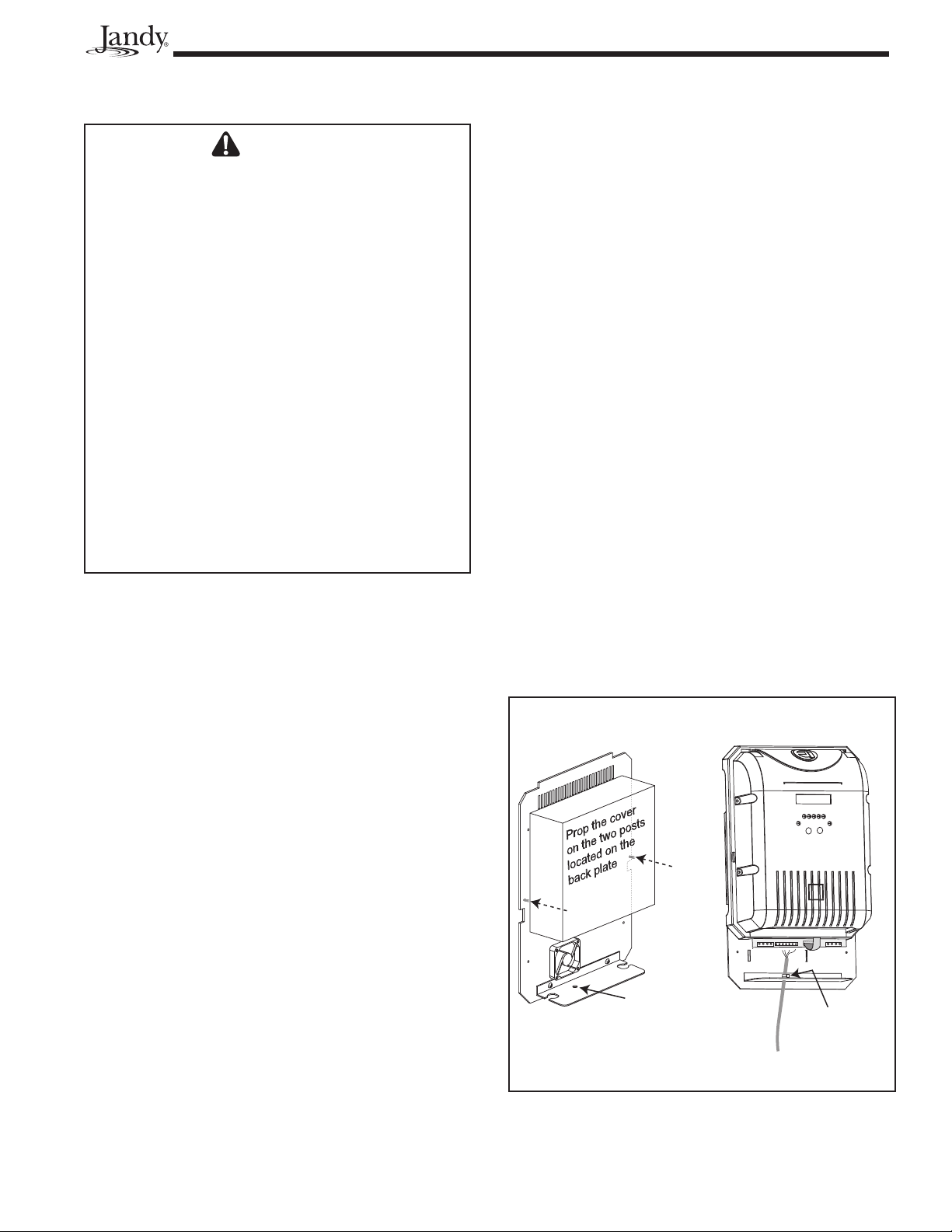
2. Remove the screws attaching the cover to the back
plate and prop the cover up to expose the terminals
(see Figure 6).
NOTE: Be careful not to pull the ribbon cable that is
connectedtothePowerSupplyandtheCover.
A. Connection to an AquaLink®RS
Control System or PDA (Optional)
The Jandy AquaLink RS or PDA is a multi-function
pool controller which can fully control the function
of the Jandy AquaPure Ei chlorine generating device.
Adjustment of the chlorine production rate can be
controlled from the main menu of the Jandy AquaLink
RS or PDA. The AquaLink RS or PDA offers individual
pool and spa settings for output percentage. Refer to
the AquaLink RS or PDA Owner’s Manual for more
information.
NOTE TheJandyAquaPureEichlorinegenerating
devicewillcommunicatewithallAquaLink
models Rev. K or later.
B. Verify the Controller Type on the Power
Pack is Set Correctly
Before wiring to an AquaLink RS Control System,
the controller type must be set to JANDY L/M to
allow communication between the power pack and the
AquaLink RS Control System. The default controller
type setting on the power pack is Jandy L/M. Follow
the instructions below to verify the controller type is set
correctly.
NOTE Thecontrollertypemustbesetcorrectlybefore
making the wiring connection between the
powerpackandtheAquaLink,otherwisethe
powerpackmaybelockedoutoftheAquaLink.
Figure 6. Accessing and Wiring to the Power PCB
Cable Tie
Comm Hole
Page 4
3. Remove the white cap covering the comm hole
(see Figure 6).
4. Thread the controller cable through the hole. A
grommet may be necessary depending on the size of
the cable being used.
5. Attach a cable tie to the controller cable as shown
(see Figure 6).
6. The JandyAquaLink®RS or PDA and power pack
use a four (4) wire connection to communicate
and can be wired up to 500 ft (152.4 m) apart.
Any outdoor rated four conductor cable, minimum
22 AWG (0.33 mm2), can be used. Locate the
appropriate screw terminals on the circuit board and
wire the power pack to the AquaLink RS or PDA
red 4-pin terminal bar (see Figure 7).
NOTE ThescrewterminalsontheAquaLinkRSor
PDAareremovabletoaidininstallation.
D. Testing the Connection
Once the power pack has been wired to the AquaLink
RS Control System or PDA, follow these steps to test
the connection:
1. Apply power to the power pack and the AquaLink
RS Control System or PDA.
2. Wait about 20 seconds. If the connection was
successful, a Ŧ symbol will appear in the top right
corner of the power pack display.
NOTE If the power pack does not connect to the
controller, turn the power off to both devices
and repeat steps 1 and 2. If the power pack
still does not connect to the controller, re-check
thewiringconnections(seeFigure7)and
the controller setting on the power pack (see
Section4.B).
Figure 7. Communication Wiring between Power
Pack and AquaLink RS Control System
or PDA Network
Jandy
Power Center
Power Pack
OPTIONAL
4321
RED
BLK
YEL
GRN
Red, 4-Pin
Terminal Bar
RED
GRN
YEL
BLK
B
A
0V
POS
RED
BLK
© 2010 Zodiac Pool Systems, Inc. All rights reserved. 0110
ZODIAC POOL SYSTEMS, INC.
2620 Commerce Way • Vista, CA • 92081
Tel: 800-822-7933 • Fax: 877-327-1403
H0342800 Rev -
ETL Listed
Conforms To
UL STD 1081
Certified to
CAN/CSA C22.2 NO. 218.1

Other manuals for AquaPure Ei Series

2

This manual suits for next models

1

Other Jandy Lighting Equipment manuals

Jandy WPLV100WS30 User manual

Jandy

Jandy WPLV100WS30 User manual

Jandy TruFit Bubbler User manual

Jandy

Jandy TruFit Bubbler User manual

Jandy Laminar Jet User manual

Jandy

Jandy Laminar Jet User manual

Jandy WaterColors CPLVRGBWS30 User manual

Jandy

Jandy WaterColors CPLVRGBWS30 User manual

Jandy AquaPure Ei Series User manual

Jandy

Jandy AquaPure Ei Series User manual

Jandy R0474000 User manual

Jandy

Jandy R0474000 User manual

Jandy AquaLink RS PS4 User manual

Jandy

Jandy AquaLink RS PS4 User manual

Jandy AquaPure Operation instructions

Jandy

Jandy AquaPure Operation instructions

Jandy CS100 User manual

Jandy

Jandy CS100 User manual

Jandy AquaLink TCX User manual

Jandy

Jandy AquaLink TCX User manual

Jandy Levolor K-1100 User manual

Jandy

Jandy Levolor K-1100 User manual

Jandy WaterColors LED User manual

Jandy

Jandy WaterColors LED User manual

Jandy AquaLink RS User manual

Jandy

Jandy AquaLink RS User manual

Jandy TruGuard User manual

Jandy

Jandy TruGuard User manual

Jandy Versa-Plumb CL340 User manual

Jandy

Jandy Versa-Plumb CL340 User manual

Jandy Jandy Pro Series User manual

Jandy

Jandy Jandy Pro Series User manual

Jandy iAquaLink 3.0 User manual

Jandy

Jandy iAquaLink 3.0 User manual

Jandy APURE35 User manual

Jandy

Jandy APURE35 User manual

Jandy TruFit JHCBUB User manual

Jandy

Jandy TruFit JHCBUB User manual

Popular Lighting Equipment manuals by other brands

Ivela 1360 quick start guide

Ivela

Ivela 1360 quick start guide

NOUVOLED LUSTROUS-FX 1910 user manual

NOUVOLED

NOUVOLED LUSTROUS-FX 1910 user manual

BenQ WiT MindDuo AR19 D user guide

BenQ

BenQ WiT MindDuo AR19 D user guide

Megaman TEMPUS FEL70700v0-em instruction manual

Megaman

Megaman TEMPUS FEL70700v0-em instruction manual

Robe ArcSource Outdoor 16 MC Integral RGBW US user manual

Robe

Robe ArcSource Outdoor 16 MC Integral RGBW US user manual

Cooper Prevail Maxx installation instructions

Cooper

Cooper Prevail Maxx installation instructions

Quantum ELMRE SP1100L quick start guide

Quantum

Quantum ELMRE SP1100L quick start guide

Ledj HEX Par 9 user manual

Ledj

Ledj HEX Par 9 user manual

Viessmann 6049 Operation manual

Viessmann

Viessmann 6049 Operation manual

Robe PATT 2013 User instructions

Robe

Robe PATT 2013 User instructions

Showline SL Strip 400 RGBW Led Luminaire user manual

Showline

Showline SL Strip 400 RGBW Led Luminaire user manual

Century REGIA LINEARE 180 RGLBI-098330 quick start guide

Century

Century REGIA LINEARE 180 RGLBI-098330 quick start guide

Alkalite Krypton KT-81 user manual

Alkalite

Alkalite Krypton KT-81 user manual

S&P PCRL80 manual

S&P

S&P PCRL80 manual

Star Headlight & Lantern DLQS-ARO Mounting instructions

Star Headlight & Lantern

Star Headlight & Lantern DLQS-ARO Mounting instructions

Saxby Lighting 75272 Instruction leaflet

Saxby Lighting

Saxby Lighting 75272 Instruction leaflet

Generac Power Systems MLT3080KV operating manual

Generac Power Systems

Generac Power Systems MLT3080KV operating manual

PANAVISION PANALUX SONARA 4:4 manual

PANAVISION

PANAVISION PANALUX SONARA 4:4 manual

manuals.online logo
manuals.online logoBrands
  • About & Mission
  • Contact us
  • Privacy Policy
  • Terms and Conditions

Copyright 2025 Manuals.Online. All Rights Reserved.