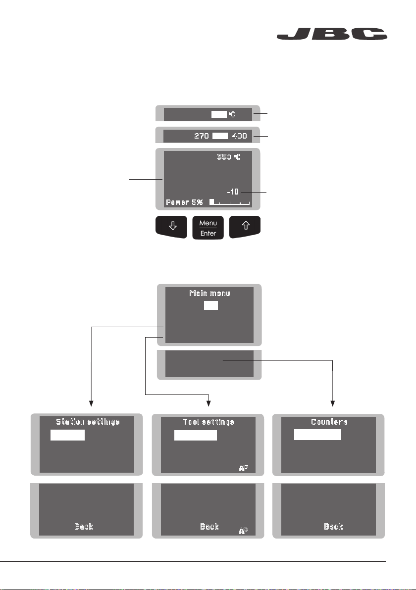
jbc CA-1E User manual

Compact Solder Feed station
Ref. CA-E
www.jbctools.com

Packing List
The following items should be included:
Power Cord ....................1 unit
Ref. 0009417 (100V/120V)
0009401 (230V)
Manual ............................ 1 unit
Ref. 0017892
Brass Wool .................... 1 unit
Ref. CL6210
Sponge ........................... 1 unit
Ref. S0354
ww w.j bc too ls.c om
Solder reel .................... 1 unit
Ref. 0002801
Allen key Ø 2.5mm ...... 1 unit
Ref. 0780493
Mobile tube Ø 1.5mm .............................. 1 unit
Ref. 0016351
Solder Feed Iron ..................................... 1 unit
Ref. AP250-A
Supplied with
guide tube for
Ø 0.8 - 1mm
Compact Solder Feed station
Ref. CA-E
CA Control Unit ......................................... 1 unit
Ref. CA-1E (120V)
CA-2E (230V)
CA-9E (100V)
2

Power Socket
Main switch
Fuse
Cable collector
Brass wool tip cleaner
with antisplash
membrane
Control
Process
Adjustable Stand:
Intelligent Heat Management
Equipotential connectionUSB-B connector
Features
Solder Feed Iron
Ref. AP250-A
www.jbctools.com
3

Adjustable stand Cable collector (Ref. CC3702)
Adjust the tool stand to suit
your work position.
Place the cable on the collector so that the working area is free
of cable.
Tip Cleaner
Splashguard
Ref. 0017576
When using the brass wool, it prevents splas-
hing of solder particles
Antisplash Membrane
Ref. 0017574
Prevents splashing and keeps the work
area clean.
Select the option to suit your needs and improve the thermal transfer of the tip.
Brass Wool
Ref. CL6210
Very effective
cleaning method.
Leaves a small layer
of solder on the tip
preventing oxidation
between cleaning
and rewetting.
Wiper Ref. CL0160
A temperature resistant receptacle for removing excess
solder by gently tapping or wiping.
If the tip is very dirty,
JBC recommends first
cleaning it with the wiper
to remove excess solder.
4

Removing the Splashguard
1. Unlock the splashguard. 2. Lift off.
Lock
More cleaning options (not supplied):
Inox Wool
Ref. CL6205
Provides a superior
cleaning of the tip.
Metal Brush
Ref. CL6220
When used carefully,
it provides a more
thorough cleaning.
Sponge
Ref. S0354
Tapping:
Tap gently to remove excess
solder.
Wiping:
Use the slots to remove
remaining particles.
Wiper
Ref. CL0160
The least harmful cleaning
method. Keep the sponge
damp with distilled water to
avoid tip wear.
www.jbctools.com
5

2. Inserting & Aligning
2. Replace
3. Fixing
3. Insert
Pull out the remaining solder
wire from the feed tube. Use a
pliers if necessary.
Pull the trigger repeatedly until
the solder wire appears at the
tip. Always use 0.8 - 1.0 mm
diameter solder wire.
Changing cartridge
Replacing solder wire
The AP250-A Solder Feed Iron works with the C250 Cartridge Range.
Find the model that best suits your soldering needs in www.jbctools.com
To change a catridge safely, unplug the tool or turn the station off before following these guidelines:
Loosen the screw and remove
the cartridge.
Use a flat pliers if still hot.
1. Removing
1. Remove
Alignment
Important: Tighten the screw
again being careful not to
over-tighten. This is necessary
for the tool to function.
Pull off the empty reel and fit
the new one.
Important: Insert the cartrid-
ge as far as the mark for a
correct connection.
Align the tip of the cartridge
with the feed tube. Use a flat
pliers to correctly align the tip.
Mark
6

USB Connector
Download the latest software from our website to update your soldering station.
JBC Updater
www.jbctools.com/software.html
Update the station software via USB connection:
Cable USB AB
JBC
Manager
JBC
Updater
JBC Manager
www.jbctools.com/manager.html
Manage and monitor as many stations as your PC can handle by using the JBC Manager.
You can export data to another PC.
Register Settings
Create graphs of the solde-
ring process in real time with
power and temperature data.
Manager Settings
Change settings for a group
of JBC stations at
the same time.
any JBC
station
USB
Hub
Cable USB AB
www.jbctools.com
7

0
c
Power 5%
350
Selected temp
350
o
C
Sleep temp 150
o
C
Sleep
0
c
350
Tool in the stand, no heat
Hibernation
0
c
350
Long time
in the
stand
Operation
The JBC Exclusive Heating System
This revolutionary technology is able to recover tip temperature extremely quickly.
This allows the user to work at a lower temperature.
As a result, tip life increases by 5.
1. Work 2. Sleep 3. Hibernation
When the tool is lifted from the
stand the tip will heat up to the
selected temperature.
When the tool is in the stand,
the temperature falls to the
preset sleep temperature.
After longer periods of
inactivity, the power is cut off
and the tool cools down to
room temperature.
· Change temperature
(from 90 to 450ºC)
· Select temperature levels
· Fix one temperature
· Change Sleep temperature
· Set Sleep delay
(from 0 to 9 min or no Sleep)
· Change Hibernation delay
(from 0 to 35 min)
8

Main menu
4 Counters
5
Program version
Exit
1 Reset settings
2
Station settings
3
Tool settings
4
Hibernation hours 0
5
No tool hours 0
6 Sleep cycles
0
Tool AP
Back
Back
1
Fix one temp -----
2
Temp levels set OFF
3
Sleep delay 0 min
5 Help text OFF
6 Beep ON
7
Change PIN
1 Temp unit
Celsius
2
Maximum temp 400
0
C
3
Minimum temp 200
0
C
4
Metronome ----
1
Plugged hours 0
2
Working hours 0
3
Sleep hours 0
Counters
Tool settings
Station settings
0
Selected temp.
350
o
C
Power 5%
Fixed temp.
350
o
C
Levels ºC
270 350 400
-10
4
Sleep temp 150
0
C
5
Hibernationdelay 10 min
6
Temp adjust + O
O
C
Tool AP
Back
c
350
Menu Screen
Original PIN: 0105
The work screen provides
useful information of tool
status in real time.
Work Screen
Control Process
Displays a specific fixed temp.
Shown when you have selected
temp. levels. The values must be
adjusted according to the work
needs.
“Temp. Adjust” parameter.
It provides a more precise
adjustment between the selected
temp and the actual one.
www.jbctools.com
9

Station Settings
Minimum temperature
Set the minimum
temperature to work with.
Min. temp. by default is
200ºC (392ºF). This is consi-
dered to be a proper starting
point for leaded applications.
Maximum temperature
Set the maximum
temperature to work with.
Max. temp by default is 400°C
(750°F). This is considered
high enough to work with
most lead-free applications.
Temperature unit
Celsius (ºC) or Fahrenheit (ºF)
Recommendations
Parameter description
N/a
Warnings
The station temperature
range is 90-450ºC
(190-840ºF). Change the
temperature limits when
working with less common
applications such as low / high
melting point soldering (HMP)
or plastics (e. g. riveting).
In most cases,
working with temperatures
over 400°C (750°F) can
damage the PCB and its
components. Even in short
time periods of tip contact
with the soldering joint, the
flux may not work properly
and could seriously reduce
tip life.
If the solder joint requires
more power (e.g. multila-
yered or high dissipation
boards), JBC strongly
recommends using other
aids like preheaters.
Be careful when using these parameters as they may reduce the tip life if not used properly.
Please follow the recommended guidelines:
Parameters
Metronome
This activates a beep sound.
Frequencies vary from 1 to 50
seconds.
Help text
Activate this parameter to
receive info from the system.
Beep
Enable/disable the beep
sound of the keypad.
Change pin
Change the default security
PIN number (0105).
The PIN must be entered
every time a parameter is
changed.
Useful for setting a work rate
in repetitive jobs. The beep
lets you know the length of
time the tip must be in contact
with the soldering joint.
N/a
N/a
N/a
N/a
N/a
N/a
10

Sleep delay
Set the time that the tool will
remain at the selected tempe-
rature when in the stand be-
fore entering sleep mode. The
tip temperature will then drop
to the Sleep temperature.
Fix one temperature
Fix a value within the
temperature range of the
station (90 - 450ºC /
190 - 840ºF).
Temperature levels set
Similar to “Fix one temp”
parameter. In this case, the
user can set up to 3 values for
different power requirements.
The sleep temperatures are
set to achieve a balance
between preventing oxidation
and reaching the working tem-
perature in a few seconds.
Ideal for soldering more than
one component at a specific
temperature. The station will
reject any attempt to change
the temperature.
This allows a quick change
between 3 different tempe-
ratures. Set them according
to the allowed values for your
soldering applications.
Because our tools reach the
working temperature from the
default Sleep mode in only a
few seconds, this parameter is
preset to 0 min. Once the tool
is returned to the stand the
temperature will automatically
drop to the sleep temperature,
extending tip life and avoiding
oxidation. Retinning the tip
before placing the tool in the
stand will protect the tip and
extend its life.
RecommendationsParameter description Warnings
N/a
N/a
Setting these
parameters to higher
values will unnecessarily
accelerate oxidation
and shorten tip life
especially when working
with temperatures up to
450°C (840°F).
Tool Settings
Sleep temperature
This is the set temperature the
tip reaches when returned to
the stand.
www.jbctools.com
11

Hibernation Delay
Set the time the tool will re-
main at Sleep temperature be-
fore entering the Hibernation
mode. At this time, the power
supply is cut off and the tip
remains at room temperature.
Tool Settings
Recommendations
Parameter description Warnings
Increasing the default
value will accelerate
oxidation and shorten the
tip life.
When the user chan-
ges the cartridge type, the
parameter should be reset
to 0°C/F or to the value
needed for this cartridge.
E.g. If a correction of
+20°C (+36°F) is set for the
C245966 (thick type) and
then the user changes the
cartridge for a C245030
(which is thinner) without
resetting, they would be
working at a temperature
of +20°C (+36°F) lower for
the C245030 which does
not need any temperature
adjustment.
This function completely
protects the tip from oxidation
during long periods of inactivi-
ty while the tool is in the stand.
Retinning the tip before pla-
cing the tool in the stand also
helps prevent oxidation and
extends the life of the tip.
Temp Adjustment
It provides a more precise
adjustment between the
selected temperature and the
actual one.
Set values within ±50°C
(± 90°F) to achieve zero error.
JBC strongly recommends the
use of TID-A or TIA-A Ther-
mometers to obtain precise
readings.
12

Clean
periodically
Before carrying out maintenance, always allow the equipment to cool.
- Clean the station screen with a glass cleaner or a damp cloth.
- Use a damp cloth to clean the casing and the
tool. Alcohol can only be used when cleaning
the metal parts.
- Periodically check that the metal parts of the
tool and stand are clean so that the station
can detect the tool status.
- Maintain tip surface clean and tinned prior to
storage in order to avoid tip oxidation.
Rusty and dirty surfaces reduce heat transfer
to the solder joint.
- Periodically check all cables and tubes.
Maintenance
1. Pull off the fuse holder and remove the
fuse. If necessary use a tool to lever it off.
2. Insert the new fuse into the holder
and return it to the station.
- Replace a blown fuse as follows:
- Replace any defective or damaged pieces. Use original JBC spare parts only.
- Repairs should only be performed by a JBC authorized technical service.
www.jbctools.com
13

It is imperative to follow safety guidelines to prevent electric
shock, injury, fire or explosion.
- Do not use the units for any purpose other than soldering or rework. Incorrect use may cause fire.
- The power cord must be plugged into approved bases. Be sure that it is properly grounded
before use. When unplugging it, hold the plug, not the wire.
- Do not work on electrically live parts.
- The tool should be placed in the stand when not in use in order to activate the sleep mode.
The soldering tip, the metal part of the tool and the stand may still be hot even when the station
is turned off. Handle with care, including when adjusting the stand position.
- Do not leave the appliance unattended when it is on.
- Do not cover the ventilation grills. Heat can cause inflamable products to ignite.
- Avoid flux coming into contact with skin or eyes to prevent irritation
- Be careful with the fumes produced when soldering.
- Keep your workplace clean and tidy. Wear appropriate protection glasses and gloves when
working to avoid personal harm.
- Utmost care must be taken with liquid tin waste which can cause burns.
- This appliance can be used by children over the age of eight and also persons with reduced
physical, sensory or mental capabilities or lack of experience provided that they have been given
adequate supervision or instruction concerning use of the appliance and understand the hazards
involved. Children must not play with the appliance.
- Maintenance must not be carried out by children unless supervised.
Safety
14

Exploded View
www.jbctools.com
15

This product should not be thrown in the garbage.
In accordance with the European directive 2002/96/EC, electronic equipment at the end of their life
must be collected and returned to an authorized recycling facility.
Manual in other languages available on our website
Warranty
JBC’s 2 year warranty covers this equipment
against all manufacturing defects, including the
replacement of defective parts and labour.
Warranty does not cover product wear or misuse.
In order for the warranty to be valid, equipment
must be returned, postage paid, to the dealer
where it was purchased.
Specifications
CA-1E 120V 50/60Hz. Input fuse: 2A. Output: 23,5V. Control Unit model: CA-1E
CA-2E 230V 50/60Hz. Input fuse: 1A. Output: 23,5V. Control Unit model: CA-2E
CA-9E 100V 50/60Hz. Input fuse: 2A. Output: 23,5V. Control Unit model: CA-9E
- Weight: 2.8 Kg (6.2 lb)
- Dimensions: 150 x 175 x 145 mm
- Output Peak Power: 130W
- Temperature Range: 90 - 450 °C (190 - 840 °F) (±5%)
- Idle Temp. Stability (still air): ±1.5 ºC / ±3 ºF
- Tip to ground resistance: <2 ohms
- Tip to ground voltage: <2mV RMS
- Ambient operating temp: 10 - 40 ºC / 50 - 104 ºF
- Diameter of Solder Wire: from 0.8 - 1 mm (0.03 - 0.04 in)
from 1.1 - 1.5 mm (0.04 - 0.06 in)
- Solder composition: Sn 99% / Ag 0.3% / Cu 0.7%
- USB connector station-PC
Complies with CE standards
ESD protected housing “skin effect”
0018181-1216
www.jbctools.comwww.jbctools.com
This manual suits for next models
3
Other jbc Soldering Gun manuals