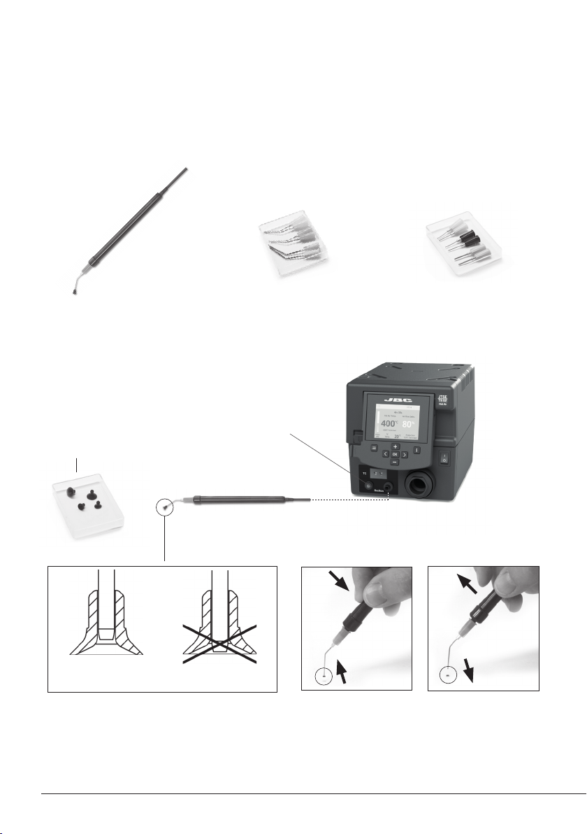
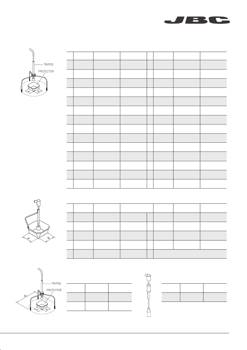
jbc TESE-A User manual

Precision Hot Air Station
Ref. TESE-A
INSTRUCTION MANUAL
www.jbctools.com

Precision Hot Air Station
Ref. TESE-A
Manual ............................ 1 unit
Ref. 0019043
Power cable .................. 1 unit
Ref. 0009417 (100V / 120V)
0009401 (230V)
Heater hose set .............1 unit
Ref. TE-TB (100V / 120V / 230V)
Stand ................................1 unit
Ref. TE-SE
TESE Control Unit .........1 unit
Ref. TESE-1A (100V / 120V)
TESE-2A (230V)
Extractor desk ...............1 unit
Ref. 0008752*
Thermocouple
Type K ...............................1 unit
Ref. PH218
Packing List
The following items are included:
TE Accessory set
Ref. 0010300
Suction Tube*
Ref. 0932330
Suction Cups*
R e f. 0 9 3 0110
Ø 10 - 0934050 (x3)
Ø 4.7 - 0934070 (x1)
Extractors*
Ref. E2184
E2064
E2052
Protectors*
Ref. P2220
P2230
P2235
P4000
P4010
Tripod*
Ref. T2050
(Ø 39mm)
T2250
(Ø 85mm)
Nozzles
Ref. TN9080 (x1)
TN9208 (x1)
TN9209 (x1)
Kapton Tape ................ 1 unit
Ref. PH217
INSTRUCTION MANUAL
2
www.jbctools.com

Hot Air button
(On / Off)
Power Socket
Fuse
USB connector
Robot RS232
connector
P-005 Pedal connector
Equipotential
connector
Auxiliar
connector
Heating element
Heater Hose set
Ref. TE-TB
Stand
Ref. TE-SE
Suction Tube
Ref. 0932330
For tripods and extractors
Thermocouple type K
Activates de suction pump
USB-A connector
Features
Main Switch
www.jbctools.com
3

17:14
20ºC
Power
45% 120ºC Selected
TC
Temp.
4m 38s
400ºC 80%
400ºC Selected
Protection
Hot Air Temp. Air Flow Selec.
Menu Options
Station
Information
Current
air
temp.
Air
temp.
selected
Instant power
supplied to
heater
Status
indicator
Selected
Air flow
Selected
External Tc
temp.
JTSE / TESE Work Screen
Status bar
The JTSE/TESE offers an intuitive user interface which provides quick access to station parameters.
Default PIN: 0105
Current
External
TC temp.
Station Tools Counters
ResetLanguage
Set the station
parameters
Set the tool
parameters
Display the hours
worked in each cycle
It is possible to
choose the language
from a list.
Allows you to carry
out an overall station
reset restoring all the
parameters to their
default values.
Station troubleshooting available on the product page at www.jbctools.com
Troubleshooting
4

Point
2/5
Temp
250
ºC
Flow
60
%
Time
2m 30s
3m 18s
Hot Air Temp
240
ºC ºC %
Ext. TC Temp
20
Air Flow
80
3m 18s
· Add point
· Delete point
· Load profile
· Save profile
· Exit
Current
air temp.
Data for
these points
Profile name
Current
air flow
Current
External
TC temp.
In this mode you can set up or edit as many as 25 profiles of temperature and air flow.
Edit Mode
Menu
Options
Profiles
Advanced functionalities
To work with profiles it is essential to use the RWB / RWS / RWT rework arms. The
Rework Arms supports the Hot Air Heater maintaining the distance and position to
the component.
www.jbctools.com
5

450
400
350
300
250
150
100
50
200
Power Temp
17:14
JBC Net
USB flash drive is connected.
Station is controlled by a PC.
Station is controlled by a robot.
System notifications
Station software update.
Press INFO to start the process.
Warning.
Press INFO for failure description.
Error.
Press INFO for failure description,
the type of error and how to proceed.
The following icons will be displayed on the screen’s status bar.
By pressing Graphics in the main MENU, temperature and power figures in real time
are displayed. This helps you decide which tip to use to obtain the best quality solder
joints.
Graphics
Temperature
Power (%) External
temp.
Ext. temp
Export graphics
Insert a USB flash drive into the USB-A
connector to save your soldering process
in csv format.
The first system to optimize traceability in soldering
- Get greater quality and control in your production
- Manage your whole soldering process remotely in real time
Station update
Download the JBC Update File from
www.jbctools.com/software.html
Insert the USB flash drive with the file down-
loadedto the station.
Files
Update
6

We recommend using the protector + tripod We recommend using the manual extractors
Protectors & Extractors
1 2 3 4
For small components (fig. 1 and 2). For large components (fig. 3 and 4).
Position the extractor with the
appropriate suction cup and
press the suction button.
Heat the component. The component lifts off
automatically when the
solder melts.
Operation
3. Extracting1. Placing 2. Heating
Adjustable Stand
Adjust the tool holder angle to suit your work position.
www.jbctools.com
7

Choose the needle and the suction cup that best fits the component and start as follows:
Operation
1. Suction 2. Release
This tool helps you place and remove SMDs of any size easily thanks to the suction pump.
Pick & Place (not supplied with TE)
Press the button to
start/stop the suction
Suction cups
Once the suction is
activated, cover the
pen hole with your
finger and lift off the
component.
Insert the needle with
the appropriate cup
for a correct suction
process.
Lift your finger to
release the component.
Make sure the needle
does not protrude
from the cup.
Pick & Place
Ref. T260-A
Straight Needles Set
Ref. 0901546
Bent Needles Set
Ref. 0861660
Maximum working temp: 250ºC (482ºF)
8

Protectors
*Ref. AxB (mm)AxB (in) *Ref. AxB (mm)AxB (in)
P3353 4,3 x 3 0.16 x 0.12 P1249 12 x 23 0.47 x 0.9
P3786 5,2 x 5,2 0.20 x 0.20 44 P4000 12,5 x 12,5 0.49 x 0.49
P3352 5,2 x 7,5 0.20 x 0.29 P3354 13,2 x 13,2 0.52 x 0.52
P3355 5,2 x 9,5 0.20 x 0.37 P4025 13,5 x 21,5 0.53 x 0.85
P3356 6,2 x 4,2 0.24 x 0.16 48 P2230 15 x 15 0.59 x 0.59
P3785 7, 2 x 7, 2 0.28 x 0.28 60 P4010 17 x 17 0.67 x 0.67
P3784 8,2 x 8,2 0.32 x 0.32 P4005 18 x 29 0.71 x 1.14
P4035 9 x 13 0.35 x 0.51 P4030 18,5 x 18,5 0.73 x 0.73
P4040 9,5 x 19 0.7 x 0 .74 P1068 18,5 x 24 0.73 x 0.94
P4080 9,5 x 21 9.5 x 0.83 P2685 28,5 x 28,5 1.12 x 1.12
32 P2220 10 x 10 0.39 x 0.39 P4085 31,5 x 31,5 1.24 x 1.24
P4045 10,5 x 21 0.14 x 0.82 P2672 33 x 46 1.30 x 1.18
P4090 11 x 16 0.43 x 0.63 P4002 50 x 50 1.97 x 1.97
24 P2235 12 x 17 0.47 x 0.67 P3357 52,5 x 14 2.06 x 0.55
øD
* Reference Desk
Tripods
Ref. øC (mm) øC (in)
T2050 39 1.53
T2250 85 3.35
Manual extractor
Ref. øD (mm) øD (in)
E2190 70.27
Extractors
*Ref. AxB (mm) AxB (in) * Ref. AxB (mm) AxB (in)
52 E2052 20 X 20 0.79 x 0.79 E4015 31,5 X 31,5 1.24 x 1.24
64 E2064 20 X 26 0.79 x 1.02 E2084 33 X 33 1.30 x 1.30
80 E2184 24 X 24 0.94 x 0.94 E2100 38 X 38 1.50 x 1.50
E2068 27 X 27 1.0 6 x 1.06 E2124 45 X 45 1.77 x 1.77
E4020 28,5 X 28,5 1.12 x 1.12
Accessories
www.jbctools.com
9

Using the Thermocouple type K
You can choose from two work modes:
Regulation: the station regulates the air
temperature automatically to maintain the
External Thermocouple (TC) temperature.
IPC* does not recommend exceeding ramp-up rates over 3-4ºC / sec. (5-7ºF / sec) so as to reduce
the risk of thermal stress on the PCB.
* IPC was founded in the U.S. in 1957 as the Institute for Printed Circuits.
Fix the TC with Kapton Tape (Ref. PH217) as near as possible to the component being worked on.
If Kapton tape is not ESD you must use an ionizer.
Protection: the station cuts the air supply off
when the External Thermocouple (TC)
temperature is reached.
Connect a TC type K (PH218) to the station and use it as a protection or regulation sensor.
You can define its use mode by means of the “Ext TC mode” option in the “Tool” menu.
10

*Ref. Shape Ø Size
(mm)
Ø
Size (in)
*TN9209 Straight Ø 3 Ø 0.12
*TN9208 Straight Ø 4 Ø 0.16
*TN9080 Straight Ø 5 Ø 0.20
TN9787 Bent Ø 3 Ø 0.12
TN9785 Bent Ø 4 Ø 0.16
TN9782 Bent Ø 5 Ø 0.20
TN8851 Bent Ø 3mm 45º Ø 0.12 45º
TN8905 Bent Ø 4 mm 45º Ø 0.16 45º
TN9561 Bent Ø 5 mm45º Ø 0.20 45º
Straight Bent
* Included in TE Accessory set (Ref. 0010300)
Turn the tool off
and handle with
care. The heating
element and the
nozzle are still hot.
2
1
Quick Nozzle Changer
Changing nozzles quickly and safely.
Ø mm Ø mm
www.jbctools.com
11

1. Ensure that the tool is turned off.
2. Use a spanner to unscrew the nut.
3. Make sure that the new heater tube fits into
the grooves in the socket.
4. Tighten the screw.
Changing the TE-TB Heater Hose Set
Only perform this operation when the element is cold and the unit is disconnected from the mains.
1. Loosen the screw.
2. Pull the heating element away from the handle.
3. Connect the new heating element, ensuring it is pushed all the way in.
4. Tighten the screw.
Replacing the Heating Element
Precision Heater
Hose Set
Ref. TE-TB
Heating Element
Ref. 0012374
(100V - 230V - 120V)
TE Handle
Ref. TE-B
12

Maintenance
Clean periodically
Fuse holder
Fuse holder
Fuse
Before carrying out maintenance, always allow the equipment to cool.
- Clean the station screen with a glass cleaner
or a damp cloth.
- Use a damp cloth to clean the casing and the
tool. Alcohol can only be used to clean the
metal parts.
- Periodically check that the metal parts of the
tool and stand are clean so that the station
can detect the tool status.
- Periodically check all cables and tubes.
- Replace a blown fuse as follows:
1. Pull off the fuse holder and remove the
fuse. If necessary use a tool to lever it off.
2. Insert the new fuse into the fuse holder
and return it to the station.
- Replace any defective or damaged pieces. Use original JBC spare parts only.
- Repairs should only be performed by a JBC authorized technical service.
www.jbctools.com
13

Safety
- Do not use the units for any purpose other than soldering or rework. Incorrect use may cause fire.
- The power cord must be plugged into approved bases. Be sure that it is properly grounded
before use. When unplugging it, hold the plug, not the wire.
- Do not work on electrically live parts.
- The tool should be placed in the stand when not in use in order to activate the sleep mode.
The soldering tip, the metal part of the tool and the stand may still be hot even when the station
is turned off. Handle with care, including when adjusting the stand position.
- Do not leave the appliance unattended when it is on.
- Do not cover the ventilation grills. Heat can cause inflamable products to ignite.
- Avoid the contact of flux with skin or eyes to prevent irritation.
- Be careful with the fumes produced when soldering.
- Keep your workplace clean and tidy. Wear appropriate protection glasses and gloves when
working to avoid personal harm.
- Utmost care must be taken with liquid tin waste which can cause burns.
- This appliance can be used by children over the age of eight and also persons with reduced
physical, sensory or mental capabilities or lack of experience provided that they have been given
adequate supervision or instruction concerning use of the appliance and understand the hazards
involved. Children must not play with the appliance.
- Maintenance must not be carried out by children unless supervised.
It is imperative to follow safety guidelines to prevent electric
shock, injury, fire or explosion.
14

产品中有害物质的名称及含量
有害物质含量表
部件名称
有害物质
铅(Pb) 汞(Hg) 镉(Cd) 六价铬
(Cr(VI))
多溴联苯
(PBB)
多溴二苯醚
(PBDE)
烙铁头 OOOOO O
手柄 OOOOO O
电源线 OOOOO O
主机 OOOOO O
电源插座 OOOOO O
保险丝 OOOOO O
主开关 OOOOO O
电位连接 X O O O O O
变压器 OOOOO O
线路板 X O O O O O
O 表示该有害物质在该部件所有均质材料中的含量均在GB/T 26572 规定的限量要求以下。
X 表示该有害物质至少在该部件的某一均质材料中的含量超出GB/T 26572 规定的限量要求。
www.jbctools.com
15

This product should not be thrown in the garbage.
In accordance with the European directive 2012/19/EU, electronic equipment at the end of its life must
be collected and returned to an authorized recycling facility.
Warranty
JBC’s 2 year warranty covers this equipment against
all manufacturing defects, including the replacement
of defective parts and labour.
Warranty does not cover product wear or misuse.
In order for the warranty to be valid, equipment must
be returned, postage paid, to the dealer where it was
purchased.
Get 1 extra year JBC warranty by registering here:
https://www.jbctools.com/productregistration/
within 30 days of purchase.
www.jbctools.com
0019043-0120
Specifications
TESE-1A 100V - 120V 50/60Hz. Input fuse: 8A. Rated current: 7A
TESE-2A 230V 50/60Hz. Input fuse: 4A. Rated current: 3A
- Temperature selection: Room temp. / 150 - 450 °C (300 - 840 °F)
- Nominal power: 700W
- Cool mode: T off. Used to blow air to room temperature
- Ambient operating temp.: 10 - 50 ºC (50 - 122 ºF)
- Air flow regulation: 5 - 50 SLPM
- Vacuum: 30% / 228 mmHg / 9 inHg
- Connectors: USB station-PC
Robot RS232
P-005 Pedal
- Control Unit Weight: 4,9 kg (10.86 lb)
- Control Unit Dimensions: 148 x 184 x 140 mm (5.83 x 7.24 x 5.51 in)
- Total Package: 474 x 368 x 195 mm / 5,69 kg
18.7 x 14.5 x 7.7 in / 12.64 lb
Complies with CE standards.
ESD protected.
Other manuals for TESE-A
1
This manual suits for next models
3
Table of contents
Other jbc Soldering Gun manuals
Popular Soldering Gun manuals by other brands

Weller
Weller EC2002M operating instructions

Pace
Pace 5050-0552 Operation and maintenance manual

Taiyo Electric
Taiyo Electric Goot RX-852AS Operation manual

Weller
Weller WXP?65 Translation of the original instructions

Weller
Weller WXsmart Translation of the original instructions

Weller
Weller WSD 130 operating instructions