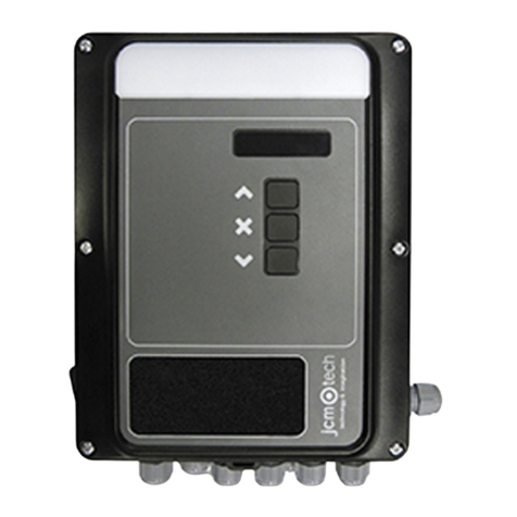
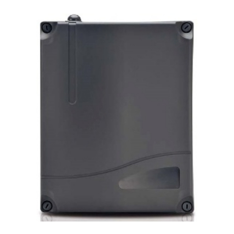
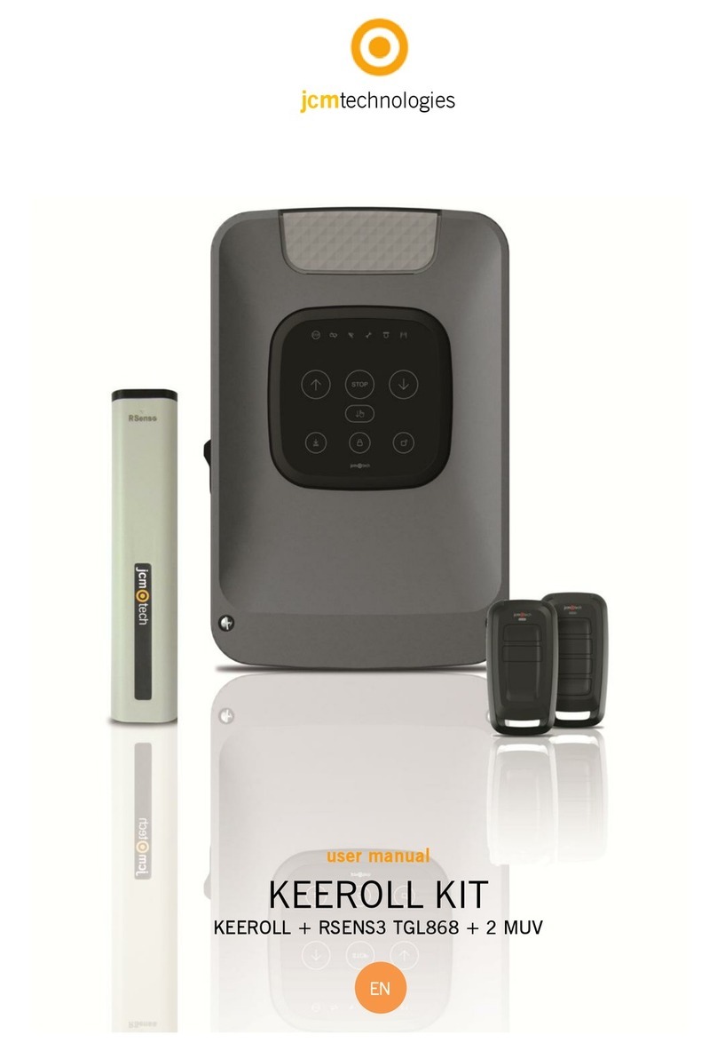
JCM Technologies KEEROLL User manual

KEEROLL
User Manual

Table of contents
Important safety instructions 3
Safety instructions for installation 3
Safety instructions for the use 4
Use of the equipment 4
Introduction 5
General description 5
Indicators 5
Actions 6
Installation 7
Control panel fixations 7
Connections 8
Configuration / Starting up 10
Connect the power supply 10
Adjusting limit switch 10
Options selection 10
Programming 11
Transmitter programming 11
Safety elements programming 11
Manoeuvre programming 12
Verification 13
Verify that the control panel is working properly 13
Transmitter 13
Safety edge 13
Photocell 13
RadioSens3 or RadioBand3 system 13
Communication’s quality 13
Impact detection adjustment 13
Maintenance 14
Program maintenance manoeuvres 14
Reset manoeuvres counter 14
Reset transmitters 14
Reset safety elements 15
Fuse replacement 15
Technical Data 16
Technical Data: KEEROLL 16
Troubleshooting 16
KEEROLL 16
Notes 17
Regulatory Data 20
EU Declaration of conformity 20
jcmtechnologies
2

Important safety instructions
Safety instructions for installation
Disconnect the power supply whenever you proceed to the installation,
maintenance or repair of the equipment.
•Before installing the panel, remove all unnecessary ropes or chains and disable any equipment such as locks that is not
necessary for the automatic operation.
•Before installing the panel, check that the door is in good mechanical condition, correctly balanced and that it opens and
closes correctly.
•Install the manual unlocking device at a height lower than 1.8m.
•Install any permanent control next to the door away from any moving part and at a minimum height of 1.5m.
•For permanently connected equipment, an easily accessible power disconnection device must be incorporated into the wiring. It
is recommended that this be of the emergency switch type.
•If the control panel is supplied without emergency stop button, this will be incorporated in the installation, connecting it to the
STOP terminal.
•For correct use of the security edge, this must never be activated when the door is fully closed. It is wise to install the ends of run
before activating the edge.
•This equipment can only be handled by a specialist fitter, by maintenance staff or by a suitably trained operator.
•To connect the power supply and motor wiring, 2.5 mm2 section terminals must be used.
•Use protective goggles when handling the equipment.
•Fuses must only be handled when the appliance is disconnected from the mains.
•The instructions for using this equipment must remain in the possession of the user.
•European door normative EN 12453 and EN 12445 specify the following minimum protection and door safety levels:
- for single-family dwellings, prevent the door from making contact with any object or limit the force of contact (e.g. safety
band), and in the case of automatic closing, it is necessary to complement this with a presence detector (e.g. photocell).
- for communal and public installations, prevent the door from making contact with any object or limit the force of contact (e.g.
safety band), and complement this with a presence detector (e.g. Photocell).
KeeRoll control panel switches automatically to dead man mode when safety devices are active
or defective. Therefore, all controls work as “hold-to-run” controls.
WARNING: IN ACCORDANCE WITH THE EN 13241-1 AND EN 12453-1 STANDARD
CONCERNING PRESSURE MAINTAINED CONTROL DEVICES:
“The person operating the door must have a direct view of the doorway, must be near the door (5 meters maximum) during
movement of the door and should not find itself in a dangerous position”. Any adjustment of the radio range out of these
recommendations, undertakes the installer in terms of responsibility for injury or damage.
“Releasing of the pressure maintained control device should stop the door movement before it scrolls 5cml”.
jcmtechnologies
3
Safety instructions for the use
•Do not allow children to play with the door controls.
•Keep the remote controls out of the reach of children.
•Watch the door movement and keep people away until the door is fully open or closed.
•Precaution when operating the manual unlocking device, as the door may suddenly fall due to the bad condition of the springs
or door unbalance. Details on how to use the manual unlocking device must be provided by the manufacturer or the device
installer.
•Examine the installation frequently, especially the cables, springs and supports, to detect signs of wear, damage or unbalance.
Do not use the door if repair work or adjustments are required, as this may cause damage.
Use of the equipment
Designed for automation of garage doors, in accordance with the general description. Not guaranteed for other uses. The
manufacturer reserves the right to alter equipment specifications without prior notification.
jcmtechnologies
4

Introduction
General description
Designed for residential aluminium roller shutters, the KEEROLL solution has direct communication with the user and the
installer.
Its capacitive front with illuminated keys provides comfort and security. The door can be opened and closed by any person
without the need for technical know-how. The installer requires no initial training in the product.
The control panel can incorporate the most advanced system for detecting obstacles via radio, without wires. Ready to work
with RadioBand3 or RadioSens3 to comply with all safety regulations. It's clean, quick and straightforward.
The system complies with standard EN ISO 13849-1: 2008, category 2, PLc.
Indicators
jcmtechnologies
5

Actions
Press to open, stop and close the door.
Press to close the door in dead man mode.
Block function: KEEROLL control panel incorporates a block button on the cover to prevent the
door from being opened accidentally.
Press to block the door, key lights ON. The control panel will not be able to move the
door neither to receive any transmitter. Useful function to block the door during the night.
Adjust courtesy light activation time: The user can set the desired time to leave the courtesy
light at on simply by pressing a button on the cover.
Frontal light Activation time
1 flash Manoeuvre time + 1 minute
2 flashes Manoeuvre time + 5 minute
3 flashes Manoeuvre time + 10 minute
Fast flashes Manoeuvre time + 1 second
New transmitters: The user can program new transmitters simply by pressing a button on the
cover (deleting transmitters is an action that is only allowed in installer mode).
ALARM device is
necessary to activ-
ate this function
Alarm function: With the ALARM accessory it is possible to detect unwanted openings of the
door (robbery), enabling the control panel’s sound alarm to be activated, or even connecting it to
the alarm system already present in the home.
Dipswitch 4 at ON. With door totally closed, if someone tries to move it manually, the alarm will
be activated.
To stop the alarm, press any button of a programmed transmitter.
jcmtechnologies
6

Installation
Control panel fixations
Remove the front cover of the control panel. Install the bottom part on the wall in a vertical position, at least 1,5 meters over
the ground and in accordance with the assembly instructions below.
jcmtechnologies
7

Connections
To prevent electric shocks, the equipment must be disconnected from the
power supply and all the electrical connections.
230VAC MONOPHASE MOTOR OUTPUTS
jcmtechnologies
8

OPTO SAFETY EDGE / 8k2 SAFETY EDGE INPUT (AUTOEDGE)
PHOTOCELL INPUT PUSHBUTTONS INPUTS
jcmtechnologies
9

Configuration / Starting up
Connect the power supply
Adjusting limit switch
Door MUST BE AT HALFWAY position before
starting the limit switch adjusting
Dipswitch 1 at ON. Door will move in dead man mode. Keep pressed or to move
up and down the door.
Press , to change the phase of the motor in case the door is not moving in the proper
sense.
Dipswitch 1 at OFF to exit dead man mode.
Options selection
Dipswitch function OFF ON
1- DEADMAN Normal operation Dead man operation
2- AUTOCLOSE Do not close automatically Close automatically
3- PRE-FLASH Pre-flash disabled 3s pre-flash enabled
4- ALARM* (KEEALARM needed) Alarm function disabled Alarm function enabled
5- COURTESY LIGHT / ALARM Courtesy light output External alarm output
6- TEST PHOTO Test photocell disabled Test photocell enabled
* Optional alarm. JCM can provide you KEEALARM
jcmtechnologies
10

Programming
Transmitter programming
Press , key lights ON, a beep will be heard.
Keep pressed key until reach the desired channel configuration (see below sequence for the different configurations).
Front light Indication
1 flash Press the desired transmitter button to
activate open / stop / close
2 flashes Press the desired transmitter button to
activate the courtesy light
3 flashes Functionless
4 flashes Press the desired transmitter button to
activate the alarm (KEEALARM needed)
Fast continuous
flashes Multichannel
Press each transmitter button to be programmed, a beep will be heard each time a transmitter is programmed.
Press again to exit radio programming, lights OFF.
Safety elements programming
Enter Installer mode: Press , the maintenance indicator lights ON, a beep will be heard.
Press the PROG button of RadioSens3 or RadioBand3 transmitters, a beep will be heard once it is programmed. The safety
element will be programmed on the first channel of the receiver.
Press again to exit Installer mode, key lights OFF and two beeps will be heard.
Both systems (RadioSens3 and RadioBand 3) cannot be programmed at the
same time. Only one of them will be operative.
jcmtechnologies
11

Manoeuvre programming
Door MUST BE TOTALLY CLOSED before starting the manoeuvre
programming.
Enter Installer mode: Press , the maintenance indicator lights ON, a beep will be heard. Select dipswitch 2 at
ON:
1-
Press , with the door
totally closed, on cover and
the control panel will initiate
and auto- programming
sequence.
7- Autoclose time.
2- Door opens 2 seconds. 8-
Press on cover and door
closes.
3- Door closes automatically. 9- Door stops.
4- Door stops. 10- Door opens automatically.
*Only with RadioSens3
5- Door opens automatically. 11- Door closes automatically.
*Only with RadioSens3
6- Door stops. 12-
Maintenance indicator
lights off. End programming.
By default, RadioSens3 system adds an inhibition zone of maximum 4cm at the end of the closing movement.
It is possible to change the inhibition zone pushing on when the door is closing. From this point, RadioSens3 will be inhib-
ited.
STOP button aborts the programming sequence.
jcmtechnologies
12

Verification
Verify that the control panel is working properly
Once the control panel is correctly wired and programmed, check that all the system (accessories included) is working prop-
erly.
Transmitter
Press the transmitter button and check that the door opens. Press again, and check that the door stops/closes.
Safety edge
Check that the LED is at OFF.
If it is activated when the door's moving, the LED will pass at ON, indicating the activation of the safety edge.
Photocell
Check that the LED is at OFF.
If it is activated when the door's moving, the LED will pass at ON, indicating the activation of the photocell.
RadioSens3 or RadioBand3 system
Check that the LED is at OFF.
If it is activated when the door's moving, the LED will pass at ON, indicating the activation of the safety element.
Communication’s quality
To ensure that the radio communication is good enough, check that the LED is at OFF. If is permanently activated,
please check RadioSens3/RadioBand3.
Impact detection adjustment
To adjust the impact detection of the RadioSens3 system, change the sensibility selector between 0 and 4.
Position Sensibility Application example
0---4 Maximum Slow doors (0,1 m/s)
If the position of the sensibility selector is changed, it is necessary to reprogram the RadioSens3
transmitter on control panel as safety elements programming (not the manoeuvre).
jcmtechnologies
13

Maintenance
Enter Installer mode: Press , the maintenance indicator lights ON, a beep will be heard.
The following functions can be done inside this maintenance mode.
Program maintenance manoeuvres
Maintenance warning: By entering Installer mode you can set the number of manoeuvres for the
maintenance warning.
Keep pressing to set up the maximum number of manoeuvres:
Frontal light Indication
1 flash 2.000 manoeuvres (or one year)
2 flashes 3.000 manoeuvres (or one year)
3 flashes 5.000 manoeuvres (or one year)
Reset manoeuvres counter
If the maintenance alarm is activated, when you press a few quick flashes will light ON and the number of
operations will be set to 0.
Reset transmitters
Press and keep pressed until and
keys starts flashing, a beep will be heard.
Keep pressed and press , to erase trans-
mitters, some beeps will be heard followed by a long beep.
jcmtechnologies
14

Reset safety elements
Press and keep pressed until and
keys starts flashing, a beep will be heard.
Keep pressed and press , to erase safety ele-
ments, some beeps will be heard followed by a long beep.
In case of erasing safety elements, the manoeuvre has to be reprogrammed
again. See Programming chapter.
Fuse replacement
When you power supply the equipment, if the frontal panel does not light, remove the front cover and replace the fuse with
another fuse with the same characteristics. You have a fuse available on the middle cover for the first time.
jcmtechnologies
15

Technical Data
Technical Data: KEEROLL
Parameter Value
Power supply range 230 V CA +/-10%
Stand-by / operating consumption <60 mA / 200 mA
Maximum power supported 1,2 kW
Motor fuses 6 A
Operating temperature -20 ºC to 55 ºC
Watertighness IP42
Size (L/W/H) 180,0 x 277,4 x 57,5 mm
Troubleshooting
KEEROLL
INDICATOR ON SOLUTION
Emergency stop input activated
Low battery detection Verify the batteries of the safety transmitter
Radio communication error
Verify the radio signal. Check the batteries,
reprogram again or change equipments loc-
ation.
ON: Installer mode
Flashing: Maintenance warning See Maintenance chapter
ON: Closing photocell activation error
Flashing: Indicates the reversed movement
after a safety detection
ON: RS3 / Safety edge activation
Flashing: Indicates the reversed movement
after a safety detection
Flashing: KEEALARM is not sending the signal
correctly
Check the batteries, verify that the installation
or the programming is ok
In case of any safety error, the door can be moved keeping pressed the or or
or any other input controls.
jcmtechnologies
16

Notes
jcmtechnologies
17

Notes
jcmtechnologies
18

Notes
jcmtechnologies
19

Regulatory Data
EU Declaration of conformity
JCM TECHNOLOGIES, S.A. hereby declares that the product KEEROLL complies with the relevant fundamental require-
ments of the RED Directive 2014/53/EU, as well as with the Machine Directive 2006/42/EC whenever its usage is foreseen;
and with the 2011/65/EU RoHS Directive.
See website www.jcm-tech.com/declarations/
JCM TECHNOLOGIES, SA
C/COSTA D'EN PARATGE, 6B
08500 VIC (BARCELONA)
SPAIN
jcmtechnologies
20
UM_3200904_KEEroll_EN_Rev03
Other manuals for KEEROLL
3
Table of contents
Other JCM Technologies Control Panel manuals

JCM Technologies
JCM Technologies F30 User manual

JCM Technologies
JCM Technologies EASY-ROLL User manual

JCM Technologies
JCM Technologies INTEGRA User manual

JCM Technologies
JCM Technologies KEEROLL User manual

JCM Technologies
JCM Technologies ROLL868 DMR User manual

JCM Technologies
JCM Technologies M42 User manual

JCM Technologies
JCM Technologies M8 User manual

JCM Technologies
JCM Technologies BASIC-PLUS User manual