Jct JPES User manual

07/2014
Version 0.1/08
JCT
ANALYSENTECHNIK GMBHBEDIENUNGSANLEITUNG
OPERATING MANUAL
J
P
ES

2 / 18
Manual J
P
ES
Inhalt
1. Einleitung 3
1.1 Montage 3
1.2 Modular 3
1.3 Service und Sicherheit 3
2. Allgemeine Sicherheitsinformation 3
2.1 Bestimmungsgemäße Verwendung 3
3. Beschreibung 4
3.1 Portable Entnahmesonde JPES 4
3.3 Beheiztes Entnahmerohr JBER 5
3.2 Beheizte Messgasleitung JHSo 5
3.4 Technische Daten JPES 6
3.5 Technische Daten JHSo 6
3.6 Technische Daten JBER 7
4. Bestellcodes 7
4.1 Lieferumfang „JPES Starter“ 9
4.2 Lieferumfang „JPES Premium“ 10
5. Installation, Sichtkontrolle 11
5.1 Installationsvorschriften 11
5.2 Montage 11
5.3 Installationsbeispiel 12
5.4 Elektrischer Anschluss 13
5.5 Elektrische Verbindungen 13
6. Deinstallation 14
7. Transport & Lagerung 14
8. Inbetriebnahme 15
9. Wartung und Service 15
9.1 Ersetzen der O-Ringe 16
9.2 Ersetzen des Filterelementes 16
10. Abmessungen 17
© 2014 JCT Analysentechnik GmbH
Reproduktion im Ganzen oder auszugsweise ohne
vorherige schriftliche Genehmigung verboten.
Alle verwendeten Markenzeichen sind Eigentum der
entsprechenden Rechteinhaber.
JCT bietet diese Betriebsanleitung "wie vorliegend" ohne
jede Garantie in irgendeiner Art, weder ausdrücklich
noch stillschweigend, einschließlich Garantien oder
Bedingungen der Marktgängigkeit oder Eignung für
einen bestimmten Zweck.
Technische Änderungen vorbehalten.
BA_DE_JPES_v1.4.doc
Table of Content
1. Introduction 3
1.1 Mounting 3
1.2 Versatile 3
1.3 Service and security 3
2. General safety information 3
2.1 Intended Use 3
3. Description 4
3.1 Portable sample probe JPES 4
3.2 Heated sample hoser JHSo 5
3.3 Heated sample pipe JBER 5
3.4 Technical data JPES 6
3.5 Technical data JHSo 6
3.6 Technical data JBER 7
4. Order codes 7
4.1 Scope of delivery „JPES Starter“ 9
4.2 Scope of delivery „JPES Premium“ 10
5. Installation, unpacking 11
5.1 Installation instructions 11
5.2 Mounting 11
5.3 Installation example 12
5.4 Electrical connection 13
5.5 Electrical interface 13
6. Demounting 14
7. Transport & storage 14
8. Commissioning / start-up 15
9. Maintenance and service 15
9.1 Replacement of O-rings 16
9.2 Replacement of filter element 16
10. Dimensions 17
© 2014 by JCT Analysentechnik GmbH
Reproduction in whole or in part in any form or medium
w
ithout written permission is prohibited
All trademarks not explicitly mentioned are property of
their legal owners.
JCT provides this operating manual "as is" without any
warranty of any kind, either express or implied, including
warranties or conditions o
f merchantability or fitness for
a particular purpose.
Subject to technical modifications without notice.

3 / 18
Manual J
P
ES
1.
Einleitung
Die beheizte Gasentnahmesonde JPES dient zur
Entnahme von staub - und aerosolhaltigen Gasen bei
extraktiven Analysensystemen, speziell für nicht
stationäre Messaufgaben. Wasserdampf und hohe
korrosive Gasfeuchte müssen über dem Taupunkt
gehalten werden, damit keine Veränderung des Gases
vor den Analysengeräten oder der Probenaufbereitung
stattfinden kann.
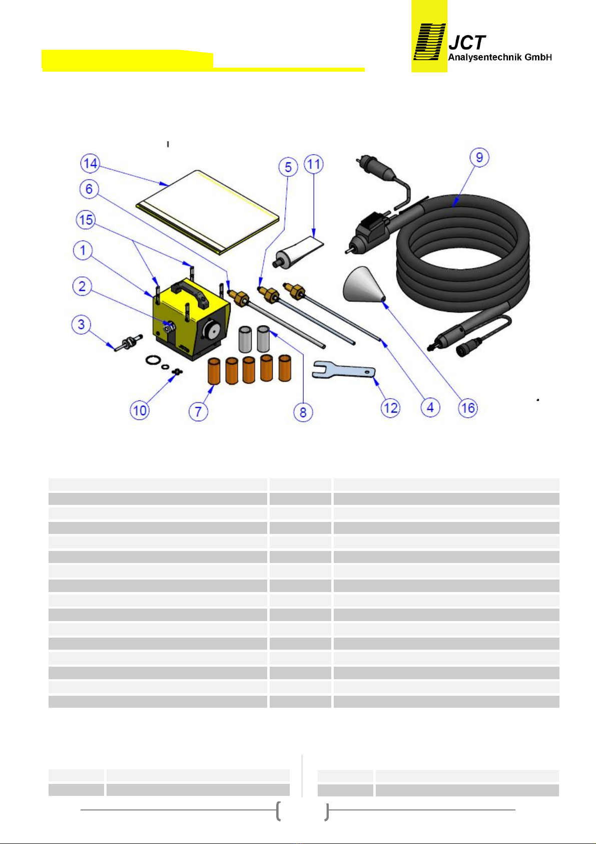
Die Gasentnahmesonde JPES ist mit umfangreichem
Zubehör und verschiedenen Filterelementen lieferbar.
Dadurch können unterschiedliche Problemstellungen
gelöst werden.
Die JPES ist mit einem großflächigen, austauschbaren
beheizten Filterelement ausgestattet. Das Filterelement
ist in einem elektrisch beheizten und thermisch isolierten
Edelstahlgehäuse montiert und zusätzlich in einem
Gehäuse untergebracht. Die Temperaturregelung erfolgt
durch eine wartungsfreie PTC Heizung. Die beheizte
Messgasleitung der Serie JH-SO 9412 wird direkt am
Gehäuse der Sonde über einen Quick On Anschluss
montiert.
Für eine korrekte und optimale Auswahl der
verschiedenen Entnahmerohre und Materialien sowie
Filtereinsätze steht Ihnen unser geschultes Personal
gerne zur Seite.
1.1 Montage
Die Entnahmesonde besteht aus dem beheizten
Filterkopf, und Montagematerial. Die Sonde wird direkt
an der Entnahmeöffnung oder Prozessflansch montiert.
Wenn die Montage horizontal erfolgt, sollte die JP
ES
zumindest zwischen 5° und 15° aus der Horizontalen
fallend eingebaut werden, damit anfallendes Kondensat
zurück in den Prozess abgeleitet werden kann.
1.2 Modular
Unterschiedliche Entnahmerohre – beheizt und
unbeheizt -, Materialien und Filter sowie beheizte
Messgasleitungen machen die JPES anpassungsfähig
für verschiedenste Applikationen.
1.3 Service und Sicherheit
Der Filterwechsel kann ohne Werkzeug und ohne
Demontage der beheizten Messgasleitung durchgeführt
werden.
2. Allgemeine Sicherheitsinformation
Die Gasentnahmesonden sind hochentwickelte Geräte,
die nur von qualifiziertem Personal bedient werden
dürfen. Es ist notwendig, dass dieses Handbuch von
jenen, die diese Ausrüstung installieren, benutzen bzw.
warten, gelesen und verstanden wurde.
2.1 Bestimmungsgemäße Verwendung
Die portable, beheizte Gasentnahmesonde JPES ist für
den mobilen Einsatz in Gasanalysesystemen bestimmt.
Beachten Sie die Angaben in den technischen
Spezifikationen hinsichtlich Umgebungs- und
Versorgungsbedingungen sowie zulässige Temperatur-
grenzen. Dieses Gerät darf nicht in explosions-
gefährdeten Bereichen betrieben werden.
1.
Introduction
The JPES series of heated gas sample probes
is
designed for use
with dust and aerosol containing gases
in extractive sampling systems
, especially for
measurement in not stationary applications. W
ater
vapour and high dew point corrosive gases must be kept
above their dew point to prevent corrosion and sample
degradation prior to the analysis or sample conditioning.
The JPES can be delivered with a large assortment of
accessories and several filter elements to meet user
specific applications.
The JPES incorporates a non-corrosive heated,
replaceable filter element. The filter element is mounted
in a thermal isolated and electrically heated
stainless
steel housing covered by a protection enclosure.
The temperature regulation is done by a maint
enance
free, PTC heater. The heated sample line JH-
SO 9412
series is directly connected with the probe housing with
a Quick On connection.
For proper selection of various sample pipe
constructions and materials as well as filter elements
please refer to our trained personal.
1.1 Mounting
The complete unit consists of the heated filter head,
mounting and installation material. The probe is mount
ed
directly to a sampling hole or flange. If the assembly
takes place horizontal, the JPES should be built
in an
angle at
least between 5° and 15° from the horizontals
falling, to allow condensate flow back into the process.
1.2 Versatile
Different pipes – heated and unheated - , materials
and
filters as well as heated sample lines make the JPES
very flexible for different applications.
1.3 Service and security
Filter replacement can be done easily
without any tools
and without disconnecting the heated sample hose.
2. General safety information
Sample p
robes are sophisticated devices intended for
use by qualified personnel only.
It is necessary that this
manual is read and understood by those who will install,
use and maintain this equipment.
2.1 Intended Use
The portable heated gas sampling probe is designed for
mobile use in gas analysis systems. Please observe the
technical specifications regarding ambient and supply
conditions and admissible temperature limits. The unit is
not suitable for operation in hazardous areas.

4 / 18
Manual J
P
ES
3. Beschreibung
3.1 Portable Entnahmesonde JPES
3. Description
3.1 Portable sample probe JPES
Filterverschluss
1
Filter lock
Filterelement
2
Filter element
Isolierung
3
Isolation
QuickOnVerriegelung
4
QuickOn lock
Beheizte Messgasleitung
5
Heated sample line
Kabeldose
6
Cable connector
Leiterplatte
7
Printedcircuit board
Status
und Netzanzeige
8
Status and supply indicators
Tragegriff
9
Carrying handle
O
-
Ring
B
(Filterverschluss
aussen
)
Ø
33
mm
10
O
-
r
ing
B
(
F
ilterlock
out
side)
Ø 33
mm
O
-
Ring
A
(Filterverschluss
innen
)
Ø
15
mm
11
O
-
r
ing
A
(
F
ilterlockinside)
Ø 15
mm
O
-
Ring
C (Quick On Anschlüsse)
Ø
6
mm
12
O
-
r
ing
C
(
Quick On connectors
)
Ø6
mm

5 / 18
Manual J
P
ES
3.2 Beheizte Messgasleitung JHSo 3.2 Heated sample line JHSo
16
4
3
2
5
7
3.3 Beheiztes Entnahmerohr JBER 3.3 Heated sample pipe JBER
Quick OnSondenanschluss
1
Quick onconnector to sample probe
Integrierter Temperatur Regler
2
Integrated temperature
controller
0,3 m KabelmitKabelstecker vonHeizleitung JHSo
3
0,3 m cable with cable plug from heated hose JHSo
0,5 mKabelmit Kabeldosezur Sonde
4
0,5 m cable with cable connectorto sample probe
Doppelmantel Entnahmerohr
5
Double tubed sample pipe
Gewindeanschluss R 3/8“
6
Thread connector R 3/8”
O RingC (QuickOn Anschlüsse)
Ø
6
mm
7
O
-
ringC
(
QuickOnconnectors
)
Ø6
mm
Heizungsanzeige
8
Heater indicator
Verschiebeflanschfür Zonenmessungen
9
Positioning flange for grid measurements
AnschlusstutzenEdelstahl
1
Connector stub stainless steel
Integrierter Temperatur Regler
2
Integrated temperature controller
2 x 2 m Netz
-
und Statuskabel
3
2 x 2 m power and statuscord
0,3
m Kabel mit Kabeldose zur Sonde bzw. zum
beheiztenEntnahmerohr 4
0.3 m cable with cable connector to sample probe or
to heated sample pipe
Quick OnSondenanschluss
5
Quick onconnector to sample probe
O RingC
(QuickOn Anschlüsse)
Ø
6
mm
6
O
-
ringC
(
QuickOnconnectors
)
Ø6
mm
Heizungsanzeige
7
Heater indi
cator

6 / 18
Manual J
P
ES
3.5 Technische Daten JHSo
Beheizte Messgasleitung
Anschlussspannung
115
VAC oder
230
VAC/
50/60
Hz
Leistungsaufnahme
ca. 100W/m
Heizung
IntegrierterTemperaturRegler
Außenschutz
PA Geflecht
Außendurchmesser
35
mm
MinimalerBiegeradius
50
mm
Farbe
Schwarz
Betriebstemperatur
180°C
Aufheizzeit
< 15 min
Absicherung
Extern,bauseits
Gewicht
ca. 0,7 kg/m
3.5 Technical data JHSo
Heated samp
le line
Supplyvoltage
115
VAC or 230
VAC/
50/60
Hz
Powerconsumption
approx. 100
W/m
Heater
Integratedtemperaturecontroller
Protectionshell
PA
-
braided
Outerdiameter
35
mm
Minimal bendingradius
50 mm
Colour
Black
Operatingtemperaturemax.
+1
80°C
Heat uptime
< 15 min
Fusing
E
xternal, on site
Weight
approx.
3.4 Technische Daten JPES
Betriebsdaten
Filter
E
lement
Typen
GF, PTFE, SS
Arbeitsdruck
50 kPa
Durchfluss
Bis 200l/h filterabhängig
Medien berührte Teile
1.4571,
Viton
Betriebstemperaturnominal
+
180
°C
Betriebstemperaturmax.
+
200
°C
Aufheizzeit
<
1
5
min
Zulässige
Umgebungstemperatur
-
20…+55
°C
Schutzart
IP 22
Konstruktion
Abmessungenüber alles
155 x 188x 184 mm
(B xH xT)
Entnahmerohr(Standard)
1.4571, L= 300 mm,
Ø
10 mm
Flanschadapter Universal
20
–
60 mm
Einbauwinkel
5° bis 15°fallend
Einbaulage
Horizontal
Gewicht
3,1 kg
Gehäuse
Stahlblech,pulverbeschichtet
Gehäusefarbe
RAL 7037
Heizleitungsanschluss
Quick On (
max. 5 kg vertikale
Belastung)
Messg
asanschluss
Quick On
Kalibriergasanschluss
Quick On
Zulassungen / Zeichen
CE
Elektrik
Anschlussspannung
115
VAC oder
230
VAC/
50/60
Hz
Leistungsaufnahme
ca
. 160
W
Heizelement
PTCselbstlimitierend
Einschalts
trom
3 A
Statussignal
Potentialfreier Kontakt
Kontaktbelastung
min. 24
VDAC
/
50
mA;
max. 230 VAC / 5A cosP 0,95
Untertemperatur
Grenzwert
+150°C (
±
5°K)
Schalthysterese
±
15°K
Anschlussstecker7
-
pol.
Speisung überHeizleitung
3.4 Technical data JPES
O
perational data
Filterelement
types
GF, PTFE, SS
Operating pressure
50 kPa
Flow rate
Upto200l/h,dependingonfilterelement
Sample gas wetted parts
1.4571; Viton
Operatingt
emperaturenominal
+180°C
Operatingtemperaturemax.
+200°C
Heat upti
me
<. 15min
Permissible ambient
temperature
-
20°C...+55°C
Protectionclass
IP 22
Mechanical
Dimensionoverall
155
x
188
x
184
mm(W xHxD)
Sample pipe (Standard)
1.4571, l= 300
mm,
Ø
10
mm
Mounting flange
20
–
6
0
mm
Mounting angle
range5°to1
5°sloping down
Mounting position
H
orizontal
Weight
3,1 kg
Housing
Sheetsteel, powder coated
Housing colour
RAL 7037
Heated hose connection Quick On (max. 5 kg vertical load)
Sample gasconnecto
r
Quick On
Calibration
gas connector
Quick On
Approva
l / Sign
CE
Electrical
Supplyvoltage
115
VAC or 230
VAC/
50/60
Hz
Powerconsumption
approx. 160
W
Heaterelement
PTCself limiting
Inrush current
3 A
Status signal
V
olt freecontact
Contact load
m
in
.
24V
DAC
/
50
mA;
max. 230 VAC / 5A cosP 0,95
Lo
w temperature contact
limit
+150°C (
±
5°K)
S
witchinghysteresis
±
15°K
Connector 7
-
pin
Powersupply via heatedhose

7 / 18
Manual J
P
ES
3.6 Technische Daten JBER
Beheiztes Entnahmerohr
Anschlussspannung
115 VAC oder
230
VAC
/
50/60Hz
Leistungsaufnahme
ca. 530
W
Heizung
IntegrierterTemperatur Regler
Medienberührte Teile
1.4571
Außendurchmesser
25 mm
Nennweite Innenrohr
ID 4 mm
Längen
1000, 1500, 2000
mm
Länge über alles
1110, 1610, 2110 mm
Gewicht
1,8; 3,0; 3,6 kg
Betriebstemperatur
180°C
Messgastemperatur
max. 250°C
Aufheizzeit
<
1
5
min
Anschlussstecker 7
-
polig
Speisung überHeizleitung
Schutzklasse
IP54
Technische Änderungen vorbehalten
4. Bestellcodes
Zubehör
Art. Nr.
Messgasleitungen mit integriertemTemperaturregler
Heizleitung230 VACL
=3
m Innen 6x4
mm
34.00401
Heizleitung230 VACL
=5
m Innen 6x4
mm
34.00402
Heizleitung230 VACL
=7
m Innen 6x4
mm
34.00403
Heizleitung115 VACL
=3
m Innen 6x4
mm
34.00411
Heizleitung115 VACL
=5
m Innen 6x4
mm
34.00412
Filter
Elemente
Filtereinsatz Mikrofaser
2
µm
(5 Stk.)
34.90015
Filtereinsatz PTFE
2
µm
(3 Stk.)
34.90016
Filtereinsatz SS Siebgewebe 2
µm,inkl. Dichtung
34.90014
Entnahme
rohre
Entnahmerohr SSID/
AD
8/10
mm,max.600°C;
L= 300mm
L= 500mm
L=1000 mm
34.00307
34.00308
34.00309
Entnahmerohr SSID/AD
6/8
mm,max.600°C;
L= 300mm
L= 500mm
L=1000 mm
34.00304
34.00305
34.00306
Entnahmerohr SS
ID/
AD
4/6
mm,max.600°C;
L= 300mm
L= 500mm
L=1000 mm
34.00301
34.00302
34.00303
3.6 Technical data JBER
Heated
sample
pipe
Supplyvoltage
115
VAC or 230
VAC/
50/60Hz
Powerconsumption
approx.
530
W
Heater
Integratedtemperaturecontroller
Gas wettedparts
SS 316 Ti
Out
erdiameter
2
5
mm
Nominalwidth inner
-
pipe
ID4
mm
Length
1000, 1500, 2000 mm
Length
overall
1110, 1610, 2110 mm
Weight
1,8
; 3,0;3,6 kg
Operating temperature
+180°C
Samplegas temperature
max. 250°C
Heat up time
< 15 min
Connector 7
-
pin
Powersupp
ly via heated hose
Protectionclass
IP54
Subject to change without notice
4. Order codes
Accessories
Part.
-
No.
Heated hoses with integrated temperature controller
Heated hose 230
VAC l=3
m inside 6x4
mm
34.00401
Heated hose 230
VAC l=5
m inside 6x4
mm
34.00402
Heated hose 230
VAC l=7
m inside6x4mm
34.00403
Heated hose 115
VAC l=3
m inside6x4mm
34.00411
Heated hose 115
VAC l=5
m inside6x4mm
34.00412
Filter elements
Filter elementmicrofiber
2
µm
(5 pcs.)
34.90015
Filter element PTFE
2
µm
(3 pcs.)
34.90016
Filter SS sievefabric
2
µm
,incl. sealing
34.90014
Samplepipes
Sample pipe
SSID/O
D
8/10
mm,max.600°C;
L= 300mm
L= 500mm
L=1000 mm
34.00307
34.00308
34.00309
Sample pipe
SSID/
O
D
6/8
mm,max.600°C;
L= 300mm
L= 500mm
L=1000 mm
34.00304
34.00305
34.00306
Sample pipe
SS
ID/O
D
4/6
mm,max.600°C;
L= 300mm
L= 500mm
L=1000 mm
34.00301
34.00302
34.00303
Innenseele
PTFE
Nennweite Innenseele
ID/AD
4/
6 mm
Signalkabel
2 x 0,75²,offeneEnden
Netzanschlusskabel
Schukood.länderspezifischerStecker
Kabellänge
2
m
Schutzart
IP54
Inner core
PTFE
Nominalwidth inner
-
liner
ID/
O
D
4/
6 mm
Signal cord
2 x 0,75²,open endings
Power cord
CEE
7/7orcountryspecificplug
Cablelength
2 m
Protectionclass
IP54

8 / 18
Manual J
P
ES
Zubehör
Art.
-
Nr.
Beheizte Entnahmerohre mitintegriertem Temperaturregler
beheiztesEntnahmerohr
230VAC,L=1m
34.00610
beheiztesEntnahmerohr
230VAC,L=1,5m
34.00615
beheiztesEntnahmerohr
230VAC,L=2m
34.00620
beheiztes
Entnahmerohr
115VAC,L=1m
34.00710
beheiztesEntnahmerohr
115VAC,L=1,5m
34.00715
beheiztesEntnahmerohr
115VAC,L=2m
34.00720
Verschiebeflansch fürZonenmessungen
DN65,PN6;DIN2573; 1.4571
34.00910
3“,
1.4571
34.00900
O
-
RingfürVerschiebe
flansch
K3401001
Zubehör fürbeheizteMessgasleitungen
Adapter für Fremdfabrikate ohne Quick On
Anschluss
34.00550
Kalibriergas
Anschluss
34.00510
Montagekette (2x1
m)
34.00501
Demontagehilfe(Blechgabelschlüssel)
K3419020
Stationäre Entnahmeste
lle
:
Messgasanschluss
mitKlemmringzumEinschrauben
Auf
Anfrage
Stationäre Entnahmestelle
:
Messgasanschluss
mitKlemmringzumEinschweißen
Auf
Anfrage
MobilerEntnahmeAnschlussadapterUniversal
(kegelförmigfürRohrdurchmesser20-60mm)
K3419030
Versc
hleißteile
O
-
Ring A (Filterverschluss innen)
Ø
15
mm
34.90011
O
-
Ring B (Filterverschluss außen)
Ø3
3
mm
34.90013
O
-
Ring C
(QuickOn Anschlüsse)
Ø
6
mm
34.90012
O
-
Ring Satz bestehend aus
:
1xO
-
Ring A,
1x
O-RingB, 4xO-RingC
34.90010
PTFE Paste
113,4
g T
ube
K3419010
Ersatzteile
Filterverschluss komplett
34.00520
Kalibrier
gas
Blindstopfen
34.90025
Transport
koffergelbmitFormteilen
P3400100
Accessories
Part.
-
No.
Heated pi
pes
with integrated temperature controller
heated
sample
pipe230
VAC, l=1
m
34.00610
heated
sample
pipe230
VAC, l=1,5
m
34.00615
heated
sample
pipe230
VAC, l=2
m
34.00620
heated
sample
pipe115
VAC, l=1
m
34.00710
heated
sample
pipe115
VAC, l=1,5
m
34.00715
heated
sample
pipe115
VAC, l=2
m
34.00720
Positioning fl
ange for grid measurements
DN65, PN6;DIN2573; SS 316Ti
34.00910
3“,
SS 316Ti
34.00900
O
-
ring for positioning flange
K3401001
Accessories for heated
sample
lines
Adapter for third
-
party heated lines without
QuickOnconnection
34.00550
Calibra
tion gasc
onnector
34.00510
Mounting chain (2x1
m)
34.00501
Disassembling aid (flat spanner)
K3419020
Stationary sampling point: sample gas
connector withferrule for screwin mounting
On
request
Stationary sampling point: sample port with
ferruleweldedinmounting
On request
Mobile sample point adapter
u
niversal
(cone-shaped for pipe diameter20-60 mm)
K3419030
Consumables
O
-
ring A(
F
ilterlockinside)
Ø 15mm
34.90011
O
-
ringB (
F
ilter lock outside)
Ø 33mm
34.90013
O
-
ring C(
Quick On connectors
)
Ø
6mm
34.90012
O
-
ring set
consistingof:1xO
-
r
ing A,
1xO
-
ring B, 4x O-ringC
34.90010
PTFE paste
113,4
g collapsible tube
K3419010
Spareparts
Filter lockcomplete
34.00520
Calibration
gas
tamp
ing
34.90025
Carrying case yellow with shell moulds
P340
0100

9 / 18
Manual J
P
ES
4.1 Lieferumfang „JPES Starter“ 4.1 Scope of delivery “JPES Starter”
Inhalt
Content
1x
PortableEntnahmesonde JPES
1
1x Portable sample probe JPES,
1x Kalibriergas
Blindstopfen
2
1x Calibration gastamping
1x Entnahmerohr Ø
10
mm
, Länge 300 mm
3
1x S
ample pipe Ø
10
mm, length 300
mm
1x Filtereinsatz Mikrofaser
4
1x Filter microfiber
1x
Beheizte Messgas
leitung 3
m
5
1x H
eated sample
line
3
m
1x Demontagehilfe
6
1x Disassembling aid
1x
Transport
koffer
*
7
1x Carrying case
*
1x Betriebsanleitung
8
1x Operating manual
1x Montagekette (L=2
x
1
m)
9
1x Mounting c
hain (l=2
x
1
m)
1x Entnahme Anschlussadapter Universal
10
1x Universal sample pipe adapter
*…
ohne Abbildung
*...without illustration
Artikelnummern
34
.
00150
JPESX Starter Kit, 115VAC
34.00250
JPES Starter Kit, 230 VAC
Part
numbers
34
.
0
0150
JPESX Starter kit, 115 VAC
34.00250
JPES Starter kit, 230 VAC

10 / 18
Manual J
P
ES
Inhalt
Content
1x
Portable Entnahmesonde
JPES
1
1x
Portable sample probe
JPES
1x
Kalibriergas
Blindstopfen
2
1x
Calibration gas
tamping
1x
Kalibriergas Anschluss
(
Auf Anfrage
mit
Fitting
)
3
1x
Calibration gasconnector (on request with fitting)
1x Ent
nahmerohr Ø
6
mm
, Länge 300 mm
4
1x S
ample pipe Ø
6
mm, length 300
mm
1x Entnahmerohr Ø
8
mm
, Länge 300 mm
5
1x S
ample pipe Ø
8
mm, length 300
mm
1x Entnahmerohr Ø
10
mm
, Länge 300 mm
6
1x S
ample pipe Ø
10
mm, length 300
mm
5x Filtere
lement
Mikrofaser
7
5x Filter
element
microfiber
2x Filtere
lement
PTFE
8
2x Filter
element
PTFE
1x
Beheizte Messgas
leitung 5
m
9
1x H
eated sample
line
5
m
1x O
-
Ring Satz
10
1x O
-
ring set
1x PTFEPaste
113,4
g Tube
11
1x PTFE paste
113,4
g collapsible tube
1x Demontagehi
lfe
12
1x Disassembling aid
1x
Transport
koffer
*
13
1x Carrying case
*
1x Betriebsanleitung
14
1x Operating manual
1x Montagekette (L
=
2
x
1
m)
15
1x Mounting chain (l
=
2
x
1
m)
1x Entn
ahme Anschlussadapter Universal
16
1x Universal sample pipe adapter
*…
ohne Abbildung
*...without illustration
Artikelnummern
34.0018
0
JPESX Premium Kit, 115 VAC
34.00280
JPES Premium Kit, 230 VAC
Part numbers
34.00180
JPESX
Premium
k
it, 115
V
AC
34.00280
JPES
Premium
k
it, 230
V
AC
4.2 Lieferumfang „JPES Premium“ 4.2 Scope of delivery „JPES Premium“

11 / 18
Manual J
P
ES
5. Installation, Sichtkontrolle
Nach dem Auspacken ist das Gerät auf allfällige
Transportschäden zu untersuchen. Wurde ein Schaden
festgestellt, sind unverzüglich die verantwortliche
Spedition und/oder der Händler zu benachrichtigen.
Es ist zu überprüfen, ob die Gerätelieferung hinsichtlich
Vollständigkeit und Type Ihrer Bestellung entspricht.
5.1 Installationsvorschriften
·Bei Arbeiten am elektrischen Teil des Gerätes ist es
vom Netz zu trennen.
·Das Gerät muss entsprechend den örtlich geltenden
Vorschriften angeschlossen und mit einem Leiter
ausreichenden Querschnitts geerdet werden.
·Die JPES Entnahmesonde muss immer mit einer
Mindestneigung gegen das Entnahmerohr hin
montiert werden. Dies ist erforderlich um einen
allfällig möglichen Rückfluss des Kondensates in die
Entnahmesonde zu verhindern.
5.2 Montage
·Filterelement gemäß Beschreibung einsetzen.
(siehe Kapitel „Wartung und Service“).
·Entnahmerohr einstecken und mit der
Überwurfmutter handfest festziehen.
ACHTUNG!
Die Dichtung erfolgt radial. Nur handfest anziehen!
HINWEIS!
Ein leichte seitliche Beweglichkeit des Entnahmerohres
ist normal, da die Abdichtung radial erfolgt.
·Sonde mit Dichtung oder Universal-Adapter unter
Zuhilfenahme von PTFE Paste an Prozessflansch
oder Entnahmeöffnung montieren. (siehe
„Installationsbeispiel“)
·Der im Lieferumfang enthaltene Universal-Adapter
ist bis zu einer Rohrnennweite von 60mm passend.
Größere Durchmesser sind auf Anfrage erhältlich.
·JPES Sonde mit Montagekette abhängen.
·Einbauwinkel gemäß technischer Spezifikation
beachten.
·Heizleitung durch Herausziehen der Quick On
Verriegelung und Einstecken der Heizleitung an die
JPES Entnahmesonde anschließen. Anderes Ende
der beheizten Messgasleitung an
Messgasaufbereitung oder Analysator anschließen.
·Elektrische Verbindungen, Versorgung sowie
Statuskontakt für den Analysator herstellen.
·Kabeldose der beheizten Messgasleitung (4) mit
Sonde verbinden.
5. Installation, unpacking
Check instrument for any damage caused by shipping. If
any damage is established, contact the carrier and
/or
distributor immediately.
Check instrument and any other delivered
parts against
order.
5.1 Installation instructions
·Disconnect mains before working on electrical part
of equipment.
·The equipment has to be connected and additionally
grounded with a wire of sufficient diameter according
to the local rules and regulations.
·The JPES sample
probe mounting has to be done
always with a minimum inclination
towards the
sampling pipe. This is necessary to prevent a
possible flow back from condensate into the probe.
5.2 Mounting
·Mount filter element according to description.
(Refer to chapter “Maintenance and service”).
·Push in sample pipe and tighten union nut stalwart.
CAUTION!
Sealing is radial. Tighten stalwart only!
NOTE!
Lateral mobility of sample pipe is normal as sealing is
radial.
·Mount probe with gasket or universal adapter with
aid of some PTFE paste on the process flange or
sampling hole. (see “Installation example”)
·The universal adapter which
is part of the set is
suitable for nominal pipe sizes up to 60mm.
Adapters for larger diameters are available on
request.
·Hang up JPES sample probe with mounting chain.
·Take care for correct mounting angel according to
technical specification.
·Connect sample line to the JPES by pulling out the
Quick On lock and pushing in the sample line. Then
connect the other end to the sample conditioning or
analyser.
·
Establish electrical connections, supply as well as
the status contact for the analyser.
·Connect cable connector of heated sample line (4)
with sample probe.

12 / 18
Manual J
P
ES
·
bei beheiztem Entnahmerohr: elektrische
Verbindung von Messgasleitung über Entnahmerohr
zu Sonde führen, dh. Kabelstecker (3) des beheizten
Entnahmerohrs mit beheizter Messgasleitung
verbinden und Kabeldose (4) mit der Sonde.
ACHTUNG!
Quick On Verriegelung muss vollständig einrasten.
ACHTUNG!
Bei Messgastemperaturen über 250°C Entnahmesonde
nicht bündig, sondern nur mit entsprechendem Abstand
oder mit Thermoschutzmatte verwenden.
HINWEIS!
Die Maximal-Temperatur für den Universal-
Adapter
beträgt 250°C.
5.3 Installationsbeispiel
·
for heated sample pipe: install electrical connection
from heated sample line via heated sample pipe to
probe, i.e. connect cable plug (3) of heated sample
pipe with heated sample hose and cable connector
(4) with probe.
CAUTION!
Quick On must lock into place properly.
CAUTION!
If the sample gas temperature exceeds 250°C, mount
sample probe not flush but in adequate distance or with
a thermal isolation mat.
NOTE!
Maximum temperature for the universal adapter is
250°C.
5.3 Installation example

13 / 18
Manual J
P
ES
5.4 Elektrischer Anschluss
·Örtliche Netzspannung, Netzfrequenz und
Leistungsaufnahme mit den Angaben auf den
Typenschildern von Sonde, beheizter
Messgasleitung und eventuell beheizt
em
Entnahmerohr vergleichen.
·Stromversorgungsanschluss herstellen und JPES
Statuskontakt für die Betriebstemperatur am
Analysator anschließen. Im Bedarfsfall ist in der
Zuführung der Energieversorgung ein 2-poliger
Netzschalter einzubauen, die JPES Entnahmesonde
besitzt keinen eigenen Netzschalter.
·Der Betreiber muss eine entsprechende
Zugentlastung aller verlegten Kabel gewährleisten.
·Eine Absicherung die den örtlich geltenden
Vorschriften entspricht ist bauseits vorzusehen.
·Beim Verlegen der Heizleitung ist auf die min.
Biegeradien sowie das mechanische Abfangen zu
achten.
5.5 Elektrische Verbindungen
WARNUNG!
Dieses Gerät wird mit Netzspannung betrieben. Beim
Betrieb dieses Gerätes stehen zwangsläufig bestimmte
Teile dieses Gerätes unter gefährlicher Spannung!
Im Betrieb kann das Gehäuse der Sonde sehr heiß
werden.
Durch Abnahme des Gehäuses werden heiße
Teile zugänglich. Bei jeglichen Arbeiten am Gerät ist
dieses abzuschalten, die Abkühlung abzuwarten. Beim
Berühren der internen Teile der JPES Entnahmesonde
besteht Verbrennungsgefahr.
Bei Nichtbeachtung der Warnhinweise können schwere
Personenschäden und/oder Sachschäden auftreten.
5.4 Electrical connection
·Check local v
oltage, frequency and power
consumption against type plates of probe, heated
line and (if applicable) heated pipe.
·Connect mains to supply outlet and JPES
temperature status contact to analyser. If needed,
connect a 2-pole switch in mains supply. The JPES
sample probe is not equipped with a switch.
·The operator must provide suitable stress relief for
all cables.
·Fusing has to be done on site according to local
rules and regulations.
·Take care of min. bending radius and mechanical
support by mounting of heated hose.
5.5 Electrical interface
WARNING!
This unit is oper
ated with mains power. During operation
some parts of the unit are energized with dangerous
voltage!
During operation the housing of the probe can become
very hot. Removing the Probe heat
cover will expose
heated parts. Disconnect power before repair or
ma
intenance and ensure that the internal temperature
has dropped to a safe level before working on it.
Touching of the JPES sampling probe internal parts can
cause burns.
If these warning notices
are ignored possible serious
injuries and/or damages may be caused.

14 / 18
Manual J
P
ES
Nur entsprechend qualifiziertes, geschultes und befugtes
Personal darf an diesem Gerät oder in dessen Nähe
arbeiten.
Dieses Personal muss mit allen Warnungen und
Instandhaltungs - Maßnahmen gemäß dieser
Betriebsanleitung vertraut sein.
Der e
inwandfreie und sichere Betrieb dieses Gerätes
setzt sachgemäßen Transport, fachgerechte Lagerung,
Aufstellung und Montage sowie sorgfältige Bedienung
und Instandhaltung voraus.
Anforderungen an die Qualifikation des Personals:
Qualifiziertes Personal im Sinne dieser Betriebsanleitung
bzw. der Warnhinweise sind Personen, die mit
Aufstellung, Montage, Inbetriebsetzung und Betrieb
dieses Produktes vertraut sind und die über eine ihrer
Tätigkeit entsprechenden Qualifikation verfügen.
6. Deinstallation
·Sonde mit Luft oder inertem Gas ca. 20 min spülen.
·Gerät anlagenseitig spannungsfrei machen und
Statuskontakt lösen.
·Beheizte Messgasleitung außer Betrieb nehmen.
·Kabeldose der Messgasleitung vom JPES bzw.
beheiztem Entnahmerohr trennen.
·Quick On Verschluss an der Sonde lösen und vom
Gehäuse nach unten abziehen.
·Sonde von der Entnahmestelle abmontieren.
·Entfernen des Entnahmerohres mit der
Demontagehilfe.
·Fachgerechte Aufbewahrung bzw. Entsorgung.
7. Transport & Lagerung
Um langjährigen und störungsfreien Betrieb
sicherzustellen sind die JPES Entnahmesonde sowie die
Messgasleitung und deren Zubehör in dafür geeigneten
Transportbehältern (z.B. JPES Sondenkoffer)
aufzubewahren und zu transportieren.
Only authorized and suitably qualified staff who have
been trained according to this manual is allowed to
operate and maintain this instrument.
For certain and safe operation the instrument needs to
be transported and stored carefully, be part of a well
planned application, installed correctly as well as
operated and maintained according to these instructions.
Qualification Requirements for staff:
Qualified staff
in the sense of this manual and/or the
warning references are persons, who are familiar with
assembly, mounting, start-up and operating of thi
s
product and have sufficient qualification for their tasks.
6. Demounting
·Purge probe with air or inert gas for approx. 20 min.
·Disconnect units supply
at site and disconnect status
contact.
·Take heated line out of service.
·Disconnect cable connector from JPES respectively
from heated sample pipe.
·Loosen Quick on lock from probe and remove it
downwards.
·Remove probe from sample duct.
·Disassemble sample pipe with disassembling aid.
·Store and dispose with expertise.
7. Transport & storage
To ensure flawless usage over many years, transport
and store of the JPES sample probe, the heated sample
line and their accessories, only in appropriate transport
cases (e.g. JPES carrying case).

15 / 18
Manual J
P
ES
8.
Inbetriebnahme
1. Kontrolle der vorschriftsgemäßen Installation
2. Überprüfung der Geräte auf Beschädigung
3. Dichtheitsprüfung durchführen
4. Sicherstellen, dass Gerät, Filterraum und Filter
sauber sind und sich keine Fremdkörper darin
befinden.
5. Kontrolle aller Anschlüsse und Leitungseinführungen
auf festen Sitz.
6. Achtung: Vor der Inbetriebnahme ist sicherzustellen,
dass die am Gerät eingestellte Betriebsspannung
und die Netzspannung übereinstimmen.
7. Energieversorgung der JPES Entnahmesonde
einschalten. Die gelbe LED leuchtet. Nach einer
Vorlaufzeit von ca. 15 Minuten leuchtet die grüne
LED auf und die Betriebstemperatur ist erreicht.
ACHTUNG!
Bei nicht Einhaltung der Kontrollschritte kann es zu
ernsthaften Gefährdungen oder zu Sach- und
Personenschäden kommen!
HINWEIS
Allfällige Geruchs- und Rauchbildung beim erstmaligen
Aufheizen ist normal und stellt keinen
Gewährleistungsanspruch dar.
Aufgabe von Kalibriergas:
1. Kalibriergas mit leichtem Überdruck einströmen
lassen.
2. Abströmen des überschüssigen Kalibriergases erfolgt
in den Prozess.
9. Wartung und Service
HINWEIS
Ist es zu Wartungs- oder Reparaturzwecken notwendig,
das Gerät an JCT Analysentechnik zu schicken, sind die
„Return Authorisation“ und die „Erklärung zur
gesundheitlichen Unbedenklichkeit“ vollständig
ausgefüllt und unterzeichnet beizulegen. Andernfalls
kann das Gerät zum Schutz der JCT Mitarbeiter nicht
übernommen werden. Die Formulare sind mit einer
gültigen Return Authorisation Number (RAN) auf
Anfrage bei der Serviceabteilung von JCT erhältlich und
stehen auf der JCT Website zum Download bereit.
8.
Commi
ssioning / s
tart up
1. Check of the proper installation
2. Review the equipment for damage
3. Check for leaks
4. Ensure that unit, filter room and filter element are
clean and no foreign particles are inside.
5. Check all connectors and cable gland´s for a tight fit.
6. Caution: Before start up of the sample probe, e
nsure
that the operating voltage of the unit and the line
voltage are identical.
7. Switch on the power supply of the JPES sample
probe. The yellow LED is turned on. After a lead
time of approx. 15 minutes the gre
en LED lights up
and the operating temperature is reached.
CAUTION!
Non-compliance with the control steps can lead to
serious hazards or property damage and personal
injury!
NOTE
Any smell or fume at the first time heat up
is normal and
is no reason for a warranty claim.
Feeding of calibration gas:
1.
Feed calibration gas with minor over pressure into
probe.
2. Excess calibration gas flows off into the process.
9. Maintenance and service
NOTE
If an item is returned to JCT Analysentechnik
, for
maintenan
ce or repair reasons, it will only be accepted
with accompanied “Return Authorisation” and
“Decontamination Statement”, fully completed and
signed. This is to ensure the security of JCT staff
. The
forms including a valid “Return Authorisation Number”
(RAN)
are available on request at the JCT service
department or for download on the JCT website.

16 / 18
Manual J
P
ES
9.1 Ersetzen der O-Ringe
O-Ringe sind Verbrauchsteile. Bei Beschädigung oder
Verhärten der O-Ring Dichtungen (A, B, C) der
beheizten Messgasleitung oder des Fil
terverschlusses
sind diese zu ersetzten.
·Dazu JPES Entnahmesonde und beheizte
Messgasleitung außer Betrieb setzten, spülen und
abkühlen lassen.
·Die zu tauschenden O-Ringe mit einem nicht
metallischen Werkzeug (Holz- oder Kunststoffkeil)
entfernen.
·Neuen Dichtring dünn mit PTFE Paste benetzen und
aufziehen.
9.2 Ersetzen des Filterelementes
Filterelemente sind Verbrauchsteile und sind abhängig
von den Einsatzbedingungen regelmäßig zu warten. Für
den Ersatz der Filterelemente sind folgende Schritte
vorzunehmen:
VERBRENNUNGSGEFAHR!
Das Gehäuse der Sonde kann sehr heiß sein.
Hitzebeständige Handschuhe benutzen.
ACHTUNG!
Bei Prozessüberdruck können toxische Gase austreten.
Entsprechende Maßnahmen sind bei Wartung und
Service sowie Ersetzen des Filterelementes zu treffen.
·Elektrische Zuleitung abschalten und warten bis die
Sonde abgekühlt ist.
·
Durch Drehen des Filterverschlusses (Pos 1)
Filterelement entnehmen.
·Filterelement (Pos. 2) vom Trägerelement (Pos 1)
abziehen. Filterelement und ggf. Flach-Dichtungen
herausnehmen.
·Filterelement (Pos. 2) und/oder Flachdichtungen
(nur bei Siebgewebefilter) ersetzen.
·Filterelement (Pos. 2) und ggf. Flachdichtungen
montieren.
·Filterelement-Verschraubung handfest anziehen.
ACHTUNG!
Die Dichtung erfolgt radial. Nur handfest anziehen!
9.1 Replacement of O-rings
O-rings are consumables.
Replace indurate or damaged
O-ring seals (A, B, C) of heated sample line or filter lock.
·Shut down JPES sample probe and heated sample
line and wait for cool down.
·Pull off O-rings with non metallic tool (wood-
or
plastic wedge).
·Apply a thin wetting of PTFE paste on O-
rings and
pull them on.
9.2 Replacement of filter element
Filter elements are consumables and have to be
replaced regularly. For replacing following steps should
be followed:
BURNING DANGER!
The housing of the probe can get very hot!
Use heat resistant gloves.
CAUTION!
Take care in case of process over pressure, possibility of
emission of toxic gases. To avoid accidents take care for
necessary safety preca
utions in case of service and
maintenance.
·Switch
off the power supply and wait for cooling
down of the probe.
·Turn away the filter lock (Pos
1) for pulling out the
filter element.
·‘Take-off the filter element (Pos 2) from the support
tube of filter lock (Pos 1). Pull out filter element and if
applicable gaskets.
·Replace the filter element (Pos 2
) and/or the gaskets
(applies only for sieve filter elements).
·Remount the filter element (Pos 2) and if applicable
the gaskets.
·Screw on the filter element-screw stalwart.
CAUTION!
Tightening is radial. Tighten stalwart only!

17 / 18
Manual J
P
ES
10. Abmessungen 10. Dimensions
184
188
155

18 / 18
Manual J
P
ES
Recycling
Das Gerät enthält Bauteile, die wiederverwertet werden
können,
sowie Bauteile, die speziell entsorgt werden
müssen. Sorgen Sie deshalb dafür, dass das Gerät nac
h
der Verwendung der Wiederverwertung zugeführt wird.
Recycling
The unit contains elements which are suitable for
recycling, and components which need special disposal.
You are therefore requested to make sure that the unit
will be recycled by the end
of its service life.
Werner Heisenberg - Str. 4 / A-2700 Wr. Neustadt / Tel +43 (0)2622 87 201 / Fax +43 (0)2622 87 2011
sales@jct.at / Firmenbuchgericht: Kreisgericht Wr. Neustadt FN 119682 d / UID - Nummer ATU 20559900
Other manuals for JPES
1
Table of contents
Other Jct Analytical Instrument manuals
Popular Analytical Instrument manuals by other brands

PCE Instruments
PCE Instruments PCE-VE 320N manual

Omron
Omron F300 installation manual

LaserLiner
LaserLiner DistanceMaster Compact Plus operating instructions

Michell Instruments
Michell Instruments XZR200 user manual

Eddyfi Technologies
Eddyfi Technologies TSC U41 user manual

PASCO
PASCO PS-3514 Instruction

LIGHTEL Technologies
LIGHTEL Technologies CI-1100-A2 user manual

Powerfix Profi
Powerfix Profi KH 2927-1 operating instructions

Meec tools
Meec tools 010972 operating instructions

explorer compact
explorer compact GL8898 user manual

Aber
Aber OPTURASPY quick start guide

Wenglor
Wenglor OY2P303A0135 operating instructions