manuals.online logo
Brands
  1. Home
  2. •
  3. Brands
  4. •
  5. Jet
  6. •
  7. Power Tools
  8. •
  9. Jet GHD-25 User manual

Jet GHD-25 User manual

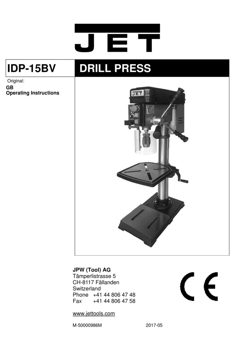
GHD-25
DRILL PRESS
Original:
GB
Operating Instructions
JPW (Tool ) AG
Tämperlistrasse 5
CH-8117 Fällanden
Switzerland
Phone +41 44 806 47 48
Fax +41 44 806 47 58
www.jettools.com
M-50000955T 201707
CE-Conformity Declaration
CE-Konformitätserklärung
Déclaration de Conformité CE
Product / Produkt / Produit:
Drill Press
Säulenbohrmaschine Perceuse
à colonne
GHD-25
Brand / Marke / Marque:
JET
Manufacturer / Hersteller / Fabricant:
JPW (Tool) AG, Tämperlistrasse 5, CH-8117 Fällanden
Schweiz / Suisse / Switzerland
We hereby declare that this product complies with the regulations
Wir erklären hiermit, dass dieses Produkt der folgenden Richtlinie entspricht
Par la présente, nous déclarons que ce produit correspond aux directives suivantes
2006/42/EC
Machinery Directive
Maschinenrichtlinie Directive
Machines
2014/35/EU
electromagnetic compatibility
elektromagnetische Verträglichkeit
compatibilité électromagnétique
designed in consideration of the standards
und entspechendr folgender zusätzlicher Normen entwickelt wurde et
été développé dans le respect des normes complémentaires suivantes
EN ISO 12100:2010
EN ISO 13849-1:2008
EN 12717:2001 + A1:2009
EN 60204-1:2006+A1:2009
Responsible for the Documentation / Dokumentations-Verantwortung / Résponsabilité de Documentation:
Hansjörg Meier
Head Product-Mgmt. / Leiter Produkt-Mgmt. / Resp. Gestion des Produits
JPW (Tool) AG
2016-05-24 Alain Schmid, General Manager
JPW (Tool) AG, Tämperlistrasse 5, CH-8117 Fällanden
Schweiz / Suisse / Switzerland
General safety notes
Milling machines can be dangerous if
not used properly. Therefore the
appropriate general technical rules as
well as the following notes must be
observed.
Read and understand the entire
instruction manual before attempting
assembly or operation.
Keep this operating instruction close by
the machine, protected from dirt and
humidity, and pass it over to the new
owner if you part with the tool.
No changes to the machine maybe
made.
Daily inspect the function and existence
of the safety appliances before you start
the machine.
Do not attempt operation in this case,
protect the machine by unplugging the
mains cable.
Do not wear gloves while operating this
machine.
Remove all loose clothing and confine
long hair.
Before operation the machine, remove
tie, rings, watches, other jewelry, and
roll up sleeves above the elbows.
Wear safety shoes; never wear leisure
shoes or sandals.
Always wear the approved working
outfit:
- Safety goggles
- Ear protection
- Dust protection
Install the machines so that there is
sufficient space for safe operation and
workpiece handling.
Keep work area well lighted.
The machine is designed to operate in
closed rooms and must be placed
stable on firm and levelled table
surface.
Make sure that the power cord does not
impede work and cause people to trip.
Keep the floor around the machine
clean and free of scrap material, oil and
grease.
Stay alert!
Give your work undivided attention.
Use common sense. Do not operate the
machine when you are tired.
Keep an ergonomic body position.
Maintain a balanced stance at all times.
Do not operate the machine under the
influence of drugs, alcohol or any
medication. Be aware that medication
can change your behavior.
Never reach into the machine while it is
operating or running down.
Never leave a running machine
unattended. Before you leave the
workplace switch off the machine.
Keep children and visitors a safe
distance from the work area.
Do not operate the electric tool near
inflammable liquids or gases.
Observe the fire fighting and fire alert
options, for example the fire
extinguisher operation and place.
Do not use the machine in a dump
environment and do not expose it to
rain.
Metal dust is explosive and can also
represent a risk to health.
Dust form some tropical woods in
particular, and form hardwoods like
beach and oak, is classified as a
carcinogenic substance.
Always use a suitable dust collection
device.
Before machining, remove any nails
and other foreign bodies from the
workpiece.
Make sure to guide and hold the chisel
with both hands safe and tight during
machining.
Work only with well sharpen tools.
Machine only stock which is chucked
securely on the machine, always check
before switching the machine on.
Provide workpieces with center holes
before clamping between centers.
Work large and unbalanced workpieces
at low spindle speed only.
Workpieces with cracks may not be
used.
Remove the chuck key or dowel pins
before turning the machine on.
Always close the belt cover.
Specifications regarding the maximum
or minimum size of the workpiece must
be observed.
Test each set-up by revolving the work
by hand to insure it clears the tool rest
and bed. Check setup at the lowest
speed before you increase to the
operating speed.
Do not remove chips and workpiece
parts until the machine is at a standstill.
Never stop workpiece with the hand
during run out.
Do not attempt to engage the spindle
lock pin until the spindle has stopped.
Never tale measurement on a rotating
workpiece.
Do not stand on the machine.
Connection and repair work on the
electrical installation maybe carried out
by a qualified electrician only.
Have a damaged or worm power cord
replaced immediately.
Make all machine adjustments or
maintenance with the machine
unplugged from the power source.
Operation Manual Total 21
page 1
Contents
1. Main use and features of the machine
2. Main technical data
3. Brief descriptio
n
of the driving system and its structure
4. Electrical system
5. Lubrication system
6. Hoisting and installation
7. Use and operation of the machine
8. Machine adjustment
9. Machine use and maintenance
10. Machine accessories
Operation Manual Total 21
page 1
Dear end-user,
Thank you very much for choosing our products. Please let us have the model of your machine,
series number, as well as the name, address and correspondence method of your company in order
to facilitate us to let you have a good service.
Important notice:
1. Please immediately contact your dealer in case the machine, accessories or documents are not
in conformity with those indicated in the packing list after the machine package is opened.
2. Please carefully read this Operation Manual particularly the electric part of this documents
before installation, testing and running the machine.
3. Removing grease on the machine (particularly on the column) and checking lubrication oil in
each place is well filled. Running the machine without lubrication oil is strictly forbidden.
Lubrication of the machine as per the stipulation of this documents is required.
4. Ground wire of the machine shall be well connected. When test running, push jog button in
slow spindle speed to check if direction of spindle revolution is correct.(clockwise)
5 Machine must be stopped if spindle speed change is necessary.
6. Please check if cutting tool or work piece is well clamped before machining.
7. The red mushroom push button located in front of the spindle box is an emergence push button
for emergency purpose and stopped the machine stopped. Familiar with its position and its use
are necessary.
8. Professional electric service engineer is required for electric maintenance.
9. When the machine working. The spindle box must be clamped otherwise. It will be hurt
operator or the machine destoryed.
10. The machine must be stopped when you need removing away the cutting material around the
drill. Moving the cutting material by hand or by hook is definitely
forbidden.
11. Correct use and daily maintenance of the machine are required in order to keep machine
accuracy and its lifetime in long time.
Operation Manual Total 21
page 2
12. We will much appreciate if you could solve some problems of the machine.
In order to facilitate us for the service, please let us know the details regarding the places and
phenomenon of the troubles if you could not solve problems.
1. Main use and features of the machine:
GHD series vertical drilling machines are our new products designed and developed by our-
self based on our accumulated experience in so many years in this field. It is universal
machine which could be widely used for small and middle sizes of work pieces for drilling,
spot facing, reaming, taping and etc. Besides, some machine tool accessories could also be
used on this machine. The machines are suitable for the machining workshop, maintenance
workshop and production line etc.
Features:
1.1 Good in appearance, easy in operation, convenience in maintenance and well
consideration in safety protection
1.2 Single speed motor is to be used for the main drive system with sufficient driving power
but saving energy. Wide spindle speed range is adopted driven by gears.
1.3 The spindle features good rigidity and good wear resisting and equipped with tool
disassembly and balancing device.
1.4 The spindle box could be turned round the column center line and could be moving up
and down following the column.
1.5 Main operation levers and push buttons could be reached easily that makes you
comfortable when you operate the machine.
1.6 Spindle feed in manual one mode , there are available in this series machines.
1.7 Superior quality material with special treatment for the wear-resisting purpose has been
used for transmission parts such as gears, worm and worm shaft, rack, lead screw etc as
well as for some key parts like spindle and spindle quill.
Operation Manual Total 21
page 3
2. Main technical data:
2.1 Main technical data
No. Name of the items Unit Data
1 Max. drilling diameter (steel) mm 25
2 Max. tapping diameter (steel) mm M18
3 Distance between spindle center line to the center line
of column mm 240
4 Max. distance between spindle end to the worktable
surface of the base mm 650
5 Max. stroke of the spindle mm 110
6 Spindle taper MT3
7 Number of speed steps of the spindle Step 6
8 Working area of the worktable of the base (L x W) mm 335×340
9 Numbers and width of the T slots of base mm 2-T14
10 Diameter of column mm φ110
11 Power and speed of the main motor kW, rpm 0.75, 1400
12 Machine dimension (L x W x H) mm 700×460×1425
13 Net weight of the machine (Net weight) kg 220
Operation Manual Total 21
page 4
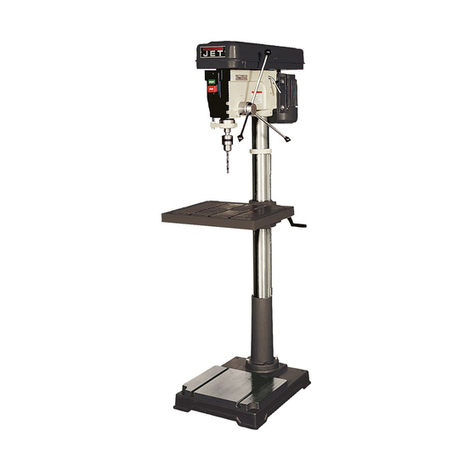
2.1 For the machine appearance and its main technical data, see diagram 1 and table 1.
3. Brief description of the driving system and its structure:
The machine consists of spindle box, column, machine base, electric cabinet and machine
accessories, total five component parts. Spindle revolution is main motion of the machine.
During drilling and milling processing, spindle movement along with its axis is a feed motion.
Spindle box up and down movement is an auxiliary motion.
Two operating levers in the front of spindle box could make changes for the spindle speed in
12 steps.Changing either lever position could drive a triple gear and a double gear moving
along with axis direction results the speed change. One of levers has an idle position that is
for the spindle rotation by manual for loading and unloading of tool cutters as well as for the
adjustment of work piece only.
Up and down movement of the spindle box is completed by manual, Adjustment for the
required distance of cutter and work piece could also be made by manual.
Please refer to the diagram 2 for the transmission system of the machine.
For the gear, worm and worm shaft, rack and pinion etc, please see table 1.
For the details of roller bears to be used on the machine, please refer to the diagram 3 and for
a list of roller bears, please refer to the table 2.
4. Electrical system
4.1 Brief description
The machine is suitable for the power supply for 400V/50HZ 3 phase. Special voltage with
60HZ could also be available as per the requirements of the end user.
4.2 Explanation of the circuit(refer to drawing4、5)
The spindle of the machine is moving by two-speed motor, it is controlled by switch(QSA1)
AC contactors (KM1) and so on.
When using the machine, the breaker QF1, fuse FU1,FU2,FU3 which is in the electrical
Box B1 must be put on, when examining and repairing, it could be put off. The spindle motor
and pump motor use breaker and fuses for his protection, and the switch features overload
protection, short cut protection and phase break protection. Press the main power switch
QS1,the electrical source HL1 light up, it is working now, contrary, work is stopped.
Operation Manual
Total 21
Page 5
Outside picture drawing (1)
1
2
Shift gear
OFF
Base
Column
Spindle box
Electric box
90
40
20
30
0
10
70
80
50
60
1"
0"
3"
2"
01400
100
110
825
4"
xmin
2825
3
4
6
7
8
9 10
13
14
12
11
Operation Manual Total21
page 6
4.1 list of gear, worm wheel, worm and rack table
(
1
)
Number on
the drawing 1 2 3 4 5 6 7 8 9
Part drawing
NO. GHD25-
1-049
N
umber of
teeth and
starts
13 19 50 15 50 22 22 32 41
Module 2.5 2.5 2 2 2 2 2 2 2
D
irection of
helical angle
Class of
Accuracy 8 8 7-6-6 7-6-6 7-6-6 9 7-6-6 7-6-6 7-6-6
Material 45 40Cr 45 40Cr 45 45 45 45 45
Heat
treatment
and hardness
T235 HV500 G52 G52 G52 G42 G52 G52 G52
Number on
the drawing 10 11 12 13 14 15
Part drawing
NO.
Number of
teeth and starts
22 15 33 1 25 30
Module 2 2 2 2 2.5 2
D
irection of
helical angle
Class of
Accuracy 7-6-6 7-6-6 7-6-6 9 9 9
Material 45 45 45 45 45 Cu
Heat
treatment
and hardness G52 G52 G52 T235 T235
GHD25-
1-014
GHD25-
1-077
GHD25-
1-078
GHD25-
1-022
GHD25-
1-022
GHD25-
1-023
GHD25-
1-079
GHD25-
1-080
GHD25-
1-088
GHD25-
1-086
GHD25-
1-087
GHD25-
1-060
GHD25-
1-065
GHD25-
1-062
Operation Manual
Total 21
Transmission Syatem Drawing (2)
Page 7
2
1
4
3
5
6
7
810 11 12
16
15
14
13
9
Operation Manual
Total 21
List and distribution of rolling bearings (3)
Page 8
2
1
4
3
5
6
7
810
13
9
Operation Manual Total 21
page 9
Roller bearing table
Table (2)
No. Model Name Specification Q’ty
Accuracy
1 GB276;302 Deep racing ball bearing 15 x 42 x 13 1
2 GB276;D105 Deep racing ball bearing 25 x 47 x 12 1
3 GB276,7000105 Deep racing ball bearing 25 x 47 x 8 2
4 GB276;D7000107 Deep racing ball bearing 35 x 62 x 9 2
5 GB276,107 Deep racing ball bearing 35 x 62 x 14 1
6 GB297,20007106 Taper roller bearing 30 x 55 x 17 1
7 GB277;50302
Deep racing ball bearing with
stop moving racing outside 15 x 42 x 13 2
8 GB277,50204 Deep racing ball bearing with
stop moving racing outside 20 x 47 x 14 1
9 GB301;8104 Thrust bearing 20 x 35 x 10 2
10 GB301;8106 Thrust bearing 30 x 47 x 11 1
Operation Manual
Total 21
Wiring Diagram (4)
Page 10
Power supply
switch QS1
Illuminating lamp
EL1(SB5)
Spindle motor M1
Electric box B1 Reverse button SB4
Stop button SB2
Push button SB3
Emergency button
SB1
OFF
Attention: The diameter of the line without indicating is 0.75mm .
2
supply
Power
Electric System Diagram (5)
Operation Manual
equipment dividing line
KM1 KM2
M
S
3
M
S
3
M1
0.75kW 0.18kW
M2
1.5mm
2
V3U3 W3 V6U6
SX1
2
0.75mm
W6
L1
L3
L2
PE
3φ AC400V 50Hz
Total power supply
advise 5A
QS1
V2U2 W2
QF1
U1
V1
W1
Spindle motor
switch
Chief coolant
pump
KM1
HL1 EL1
8
KM1
KM2
6
5
SB3
11
KM2
KM1
KM2
9
SB4
1.5mm
FU2
(3A)
Power supply
1.5mm
2
SB2
(3A)FU3
AC24V
T1
2
FU1
(3A)
U4 W4
Rotation
Illuminating
lamp rotation
Reverse
2
Page 11
Total 21
SQ1
12
13
SQ2
3
4
SB1
Operation Manual Total 21
page 12
4.3 Machine operation
Put the switch (QSA1) at the position which is required (“1” main motor 1440 r/min.”2”main
Motor 2880 r/min, “R” the reversion of main motor, “0” machine is stopped). Press the button
SB3, it is working normally. When put the switch (QSA1) at “R”
, the main motor stop
working.
4.4 Emergency stop operation:
If emergency stop is necessary during operation, press emergency push button SQ1 that makes
the loss of electric power of the contactor KM1, so the machine is completely stopped. After
eliminating the breakdown , release the lock of the push button then restart the machine.
4.5 Maintenance of the electric equipment:
Turn off the electric power before maintenance of the electric equipment starts. The electric
equipment must keep on clean condition. Therefore, regularly cleaning is necessary.
However .liquid such as kerosene, gasoline and detergent etc. is not be allowed for the
cleaning. Wave of power supply shall not be over ±10% required by the electric motor.
Maintenance of electric equipment is absolutely important in order to keep machine works
well.
Operation Manual Total 21
page 13
4.7 Electric components list: Table (3)
Code of
elements Name Specification Q’ty Remark
QS1 Instruction switch JCH13-20 1
QF1 Breaker DZ108-1.6/2.5A 1
KM1,KM2 Connector LC1E1201B5N(AC24V)50Hz 2
LAEN20N 2
SB1 Emergency stop button LA42(B)J-11/R 1
SB2 Push button LA42(B)PJ-11/R 1
SB3,SB4 Push button LA42(B)PJ-22/G 2
HL1 Signal lamp AD17-16 AC24V 1
T1 Transformer JBK6-63TH 400/24 1
EL1 Lamp 25W AC24V 1
SX1 Selection switch LA42XL2-30/B 1
SQ1 Micro switch LXP1-020-0A 1
SQ2 Door switch JWM6-11A 1
Operation Manual Total 21
page 14
5. Lubrication system:
5.1 There are two types of lubrication in this machine:
a. Grease
b. Lubrication by manual filled oil
5.2 Gears in the spindle box are lubricated by grease, it uses NO.3 Lithium industrial grease,
for the new machine, washing and grease replacement after six months running. Later,
washing and grease replacement once a year is required.
5.3 The machine needs manual oil fill lubrication.
Manual oil fill lubrication place, see diagram (6)
6Hoisting and installation:
6.1 Hoisting:
The machine is strongly fixed inside of the crate. When hoisting the machine, please pay close
attention to the sign outside of the crate (where the wire cable shall be placed and where the
gravity center is).
The crate must not be reversed or inclined and must not be strongly stroked when lift up the
machine.
Considering small size of the bottom and higher size of the height of the machine package,
therefore, moving the machine by roller is forbidden. Lifting by a crane or by forklift is
recommended.
Please refer
to the diagram 7 for the machine lifting. A soft pad between machine and wire
cable is necessary in order to avoid paint damage of the machine. Lifting must be slow at
beginning to see if the gravity center is correct.
6.2 Installation:
Working area of the machine shall be the size when the spindle box rounds its column in one
cycle. Its diameter is about Ø2000mm. Further more, space for the work pieces, toolbox, and
machine accessories as well as operating and maintenance space must be considered.
The machine should be placed on a solid ground. No foundation construction is required if
ground of workshop is solid enough. However, we suggest that you’d better to make a
foundation as per the attached drawing 8 and shall consider some space for foundation screw
bolts use.
Operation Manual
Total 21
Lubrication Diagram (6)
Page 15
2
1
3
4
1"
0"
40
20
30
0
10
3"
2"
90
70
80
50
60
2825
4"
100
110
1400
0
825
min
x
Operation Manual
Total 21
Hoisting of the machine (7)
Page 16

Other Jet Power Tools manuals

Jet JFM-5 User manual

Jet

Jet JFM-5 User manual

Jet J-2221VS Service manual

Jet

Jet J-2221VS Service manual

Jet JDP-15B-M User manual

Jet

Jet JDP-15B-M User manual

Jet JDPE-20EVS-PDF Service manual

Jet

Jet JDPE-20EVS-PDF Service manual

Jet JAT-660 Application guide

Jet

Jet JAT-660 Application guide

Jet JJP-8BT Service manual

Jet

Jet JJP-8BT Service manual

Jet JDP-212 User manual

Jet

Jet JDP-212 User manual

Jet PROMAC 378VBC User manual

Jet

Jet PROMAC 378VBC User manual

Jet JDP-20MF Service manual

Jet

Jet JDP-20MF Service manual

Jet JAT-101 Application guide

Jet

Jet JAT-101 Application guide

Jet JDTW Series User manual

Jet

Jet JDTW Series User manual

Jet JDP-22VS User manual

Jet

Jet JDP-22VS User manual

Jet GHD-20 User manual

Jet

Jet GHD-20 User manual

Jet SR-1650N User manual

Jet

Jet SR-1650N User manual

Jet JDP-17DX Service manual

Jet

Jet JDP-17DX Service manual

Jet JHG-600K User manual

Jet

Jet JHG-600K User manual

Jet JSJ-3XA Service manual

Jet

Jet JSJ-3XA Service manual

Jet MSS-1 Service manual

Jet

Jet MSS-1 Service manual

Jet JWS-35X Series Service manual

Jet

Jet JWS-35X Series Service manual

Jet JDP-20EVS-110 Service manual

Jet

Jet JDP-20EVS-110 Service manual

Jet JWS-25CS User manual

Jet

Jet JWS-25CS User manual

Jet HP-5A User manual

Jet

Jet HP-5A User manual

Jet JDP-20EVS Service manual

Jet

Jet JDP-20EVS Service manual

Jet JAT-322 Application guide

Jet

Jet JAT-322 Application guide

Popular Power Tools manuals by other brands

Schneider Airsystems KTP 310 ALU operating manual

Schneider Airsystems

Schneider Airsystems KTP 310 ALU operating manual

Dremel 8200 Original instructions

Dremel

Dremel 8200 Original instructions

Wurth Master SBS 1300-VES Translation of the original instructions

Wurth Master

Wurth Master SBS 1300-VES Translation of the original instructions

TOOLCRAFT 81 91 61 operating instructions

TOOLCRAFT

TOOLCRAFT 81 91 61 operating instructions

EINHELL TH-HA 2000/1 Original operating instructions

EINHELL

EINHELL TH-HA 2000/1 Original operating instructions

Sealey AK303.V2 instructions

Sealey

Sealey AK303.V2 instructions

Leister ELECTRON ST user manual

Leister

Leister ELECTRON ST user manual

Flexco Novitool Ply 130 Safety and operation manual

Flexco

Flexco Novitool Ply 130 Safety and operation manual

Bosch GHG 660 LCD Professional Original instructions

Bosch

Bosch GHG 660 LCD Professional Original instructions

REXON 30A manual

REXON

REXON 30A manual

HIKOKI RH600TLAZ Handling instructions

HIKOKI

HIKOKI RH600TLAZ Handling instructions

DeWalt DCF813-XE instruction manual

DeWalt

DeWalt DCF813-XE instruction manual

Chicago Electric 68523 Owner's manual & safety instructions

Chicago Electric

Chicago Electric 68523 Owner's manual & safety instructions

Sealey YK30FAHFP instructions

Sealey

Sealey YK30FAHFP instructions

Campbell Hausfeld DG460300CK S Operating instructions and parts manual

Campbell Hausfeld

Campbell Hausfeld DG460300CK S Operating instructions and parts manual

Roller uni-press instruction manual

Roller

Roller uni-press instruction manual

Oypla 3920 user manual

Oypla

Oypla 3920 user manual

Fein KBM 50 Q instruction manual

Fein

Fein KBM 50 Q instruction manual

manuals.online logo
manuals.online logoBrands
  • About & Mission
  • Contact us
  • Privacy Policy
  • Terms and Conditions

Copyright 2025 Manuals.Online. All Rights Reserved.