Jet J-1600R Service manual

1
Operating Instructions and Parts Manual
5-ft. Radial Arm Drill Press
Models J-1600R, J-1600R-4
WALTER MEIER (Manufacturing) Inc.
427 New Sanford Road
LaVergne, Tennessee 37086 Part No. M-320038
Ph.: 800-274-6848 Revision G2 09/2013
www.waltermeier.com Copyright © 2013 Walter Meier (Manufacturing) Inc.

2
1.0 Warranty and Service
Walter Meier (Manufacturing) Inc., warrants every product it sells. If one of our tools needs service or repair, one of
our Authorized Service Centers located throughout the United States can give you quick service. In most cases, any
of these Walter Meier Authorized Service Centers can authorize warranty repair, assist you in obtaining parts, or
perform routine maintenance and major repair on your JET® tools. For the name of an Authorized Service Center in
your area call 1-800-274-6848.
MORE INFORMATION
Walter Meier is consistently adding new products to the line. For complete, up-to-date product information, check with
your local Walter Meier distributor, or visit waltermeier.com.
WARRANTY
JET products carry a limited warranty which varies in duration based upon the product (MW = Metalworking, WW =
Woodworking).
WHAT IS COVERED?
This warranty covers any defects in workmanship or materials subject to the exceptions stated below. Cutting tools,
abrasives and other consumables are excluded from warranty coverage.
WHO IS COVERED?
This warranty covers only the initial purchaser of the product.
WHAT IS THE PERIOD OF COVERAGE?
The general JET warranty lasts for the time period specified in the product literature of each product.
WHAT IS NOT COVERED?
Five Year Warranties do not cover woodworking (WW) products used for commercial, industrial or educational
purposes. Woodworking products with Five Year Warranties that are used for commercial, industrial or education
purposes revert to a One Year Warranty. This warranty does not cover defects due directly or indirectly to misuse,
abuse, negligence or accidents, normal wear-and-tear, improper repair or alterations, or lack of maintenance.
HOW TO GET SERVICE
The product or part must be returned for examination, postage prepaid, to a location designated by us. For the name
of the location nearest you, please call 1-800-274-6848.
You must provide proof of initial purchase date and an explanation of the complaint must accompany the
merchandise. If our inspection discloses a defect, we will repair or replace the product, or refund the purchase price,
at our option. We will return the repaired product or replacement at our expense unless it is determined by us that
there is no defect, or that the defect resulted from causes not within the scope of our warranty in which case we will,
at your direction, dispose of or return the product. In the event you choose to have the product returned, you will be
responsible for the shipping and handling costs of the return.
HOW STATE LAW APPLIES
This warranty gives you specific legal rights; you may also have other rights which vary from state to state.
LIMITATIONS ON THIS WARRANTY
WALTER MEIER (MANUFACTURING) INC., LIMITS ALL IMPLIED WARRANTIES TO THE PERIOD OF THE
LIMITED WARRANTY FOR EACH PRODUCT. EXCEPT AS STATED HEREIN, ANY IMPLIED WARRANTIES OR
MERCHANTABILITY AND FITNESS ARE EXCLUDED. SOME STATES DO NOT ALLOW LIMITATIONS ON HOW
LONG THE IMPLIED WARRANTY LASTS, SO THE ABOVE LIMITATION MAY NOT APPLY TO YOU.
WALTER MEIER SHALL IN NO EVENT BE LIABLE FOR DEATH, INJURIES TO PERSONS OR PROPERTY, OR
FOR INCIDENTAL, CONTINGENT, SPECIAL, OR CONSEQUENTIAL DAMAGES ARISING FROM THE USE OF
OUR PRODUCTS. SOME STATES DO NOT ALLOW THE EXCLUSION OR LIMITATION OF INCIDENTAL OR
CONSEQUENTIAL DAMAGES, SO THE ABOVE LIMITATION OR EXCLUSION MAY NOT APPLY TO YOU.
Walter Meier sells through distributors only. The specifications in Walter Meier catalogs are given as general
information and are not binding. Members of Walter Meier reserve the right to effect at any time, without prior notice,
those alterations to parts, fittings, and accessory equipment which they may deem necessary for any reason
whatsoever. JET® branded products are not sold in Canada by Walter Meier.

3
2.0 Table of Contents
Section Page
1.0 Warranty and Service.....................................................................................................................................1
2.0 Table of Contents ...........................................................................................................................................3
3.0 Safety .............................................................................................................................................................5
3.1 Machinery General Safety Warnings ............................................................................................. 5
3.2 General Electrical Cautions ........................................................................................................... 6
3.3 Safety Instructions for Drill Presses ............................................................................................... 6
4.0 Specifications ................................................................................................................................................. 7
4.1 Machining Capacities .................................................................................................................... 8
4.2 Machine Environment ................................................................................................................... 8
4.3 Power Supply Requirements ......................................................................................................... 8
4.4 Overall Dimensions, J-1600R ........................................................................................................................9
5.0 General Features and Terminology, J-1600R..............................................................................................10
6.0 Set-Up and Assembly ..................................................................................................................................12
6.1 Floor Diagrams for J-1600R ........................................................................................................ 12
6.2 Unpacking................................................................................................................................... 13
6.3 Machine Set-Up .......................................................................................................................... 14
6.4 Electrical Connections................................................................................................................. 15
7.0 Operating Controls .......................................................................................................................................16
8.0 Operation .....................................................................................................................................................17
8.1 Clamping workpieces.................................................................................................................. 17
8.2 Tool insertion .............................................................................................................................. 17
8.3 Tool positioning over workpiece .................................................................................................. 17
8.4 Unlocking arm and column mechanisms ..................................................................................... 17
8.5 Raising and lowering radial arm .................................................................................................. 18
8.6 Moving drill head along arm ........................................................................................................ 18
8.7 Rotating arm on support column.................................................................................................. 18
8.8 Setting spindle speed.................................................................................................................. 18
8.9 Feed rate and depth of cut .......................................................................................................... 19
8.10 Setting feed rate........................................................................................................................ 19
8.11 Feed methods........................................................................................................................... 19
8.12 Setting depth of cut using power feed system............................................................................ 19
8.13 Spindle direction and power feed............................................................................................... 20
8.14 Hand feed – roughing operations............................................................................................... 20
8.15 Fine hand feed using power feed system................................................................................... 20
8.16 Tapping..................................................................................................................................... 20
8.17 Power ON/OFF ......................................................................................................................... 20
8.18 Coolant control.......................................................................................................................... 21
8.19 Spindle motor controls............................................................................................................... 21
8.20 Turning off spindle drive............................................................................................................ 21
8.21 Resetting STOP switch ............................................................................................................. 21
8.22 Using load ammeter .................................................................................................................. 21
8.23 Tapping operations ................................................................................................................... 21
8.24 Arm/spindle control lever........................................................................................................... 22
9.0 Adjustments .................................................................................................................................................22
9.1 Clamping device ......................................................................................................................... 22
9.2 Head/rail backlash ...................................................................................................................... 22
9.3 Clutch adjustment ....................................................................................................................... 23
9.4 Hydraulic pressure adjustment .................................................................................................... 23
10.0 Troubleshooting the J-1600R.....................................................................................................................24
11.0 Spindle speed chart (J-1600R) ..................................................................................................................25
12.0 Maintenance for J-1600R...........................................................................................................................26
12.1 General Cleaning ...................................................................................................................... 26
11.2 Lubrication ................................................................................................................................ 26
13.0 Replacement Parts – J-1600R Radial Arm Drill .........................................................................................28
13.1.1 Riser Mechanism: Exploded View .......................................................................................... 28
13.1.2 Riser Mechanism: Parts List ................................................................................................... 29
13.2.1 Column and Base: Exploded View.......................................................................................... 30

4
13.2.2 Column and Base: Parts List .................................................................................................. 31
13.3.1 Coolant System: Exploded View............................................................................................. 33
13.3.2 Coolant System: Parts List ..................................................................................................... 33
13.4.1 Gearbox Assembly (Upper Section): Exploded View............................................................... 34
13.4.2 Gearbox Assembly (Upper Section): Parts List ....................................................................... 35
13.5.1 Gearbox Assembly (Lower Section): Exploded View............................................................... 37
13.5.2 Gearbox Assembly (Lower Section): Parts List ....................................................................... 38
13.6.1 Rear of Head: Exploded View................................................................................................. 42
13.6.2 Rear of Head: Parts List ......................................................................................................... 43
13.7.1 Feed Change Mechanism: Exploded View.............................................................................. 45
13.7.2 Feed Change Mechanism: Parts List ...................................................................................... 45
13.8.1 Hydraulic Clamping Mechanism: Exploded View..................................................................... 47
13.8.2 Hydraulic Clamping Mechanism: Parts List ............................................................................. 48
14.0 Electrical Connections for J-1600R............................................................................................................50
14.1 Electrical Connections for J-1600R: Parts List ........................................................................... 53
15.0 Hydraulic system of J-1600R ..................................................................................................................... 54
Familiarize yourself with the following safety notices used in this manual:
This means that if precautions are not heeded, it may result in minor injury and/or possible
machine damage.
This means that if precautions are not heeded, it may result in serious or even fatal injury.

5
3.0 Safety
- Misuse of this machine can cause serious injury.
- For safety, machine must be set up, used and
serviced properly.
- Read, understand and follow instructions in the
operator’s and parts manual which was shipped
with your machine.
When setting up machine:
- Always avoid using machine in damp or poorly
lighted work areas.
- Always be sure machine is securely anchored to
the floor.
- Always keep machine guards in place.
- Always put start switch in “OFF” position before
plugging in machine.
When using machine:
-Never operate with machine guards missing.
-Always wear safety glasses with side shields (See
ANSI Z87.1)
-Never wear loose clothing or jewelry.
-Never overreach — you may slip and fall into the
machine.
-Never leave machine running while you are away
from it.
-Always shut off the machine when not in use.
When servicing machine:
-Always unplug machine from electrical power
while servicing.
-Always follow instructions in operator’s and parts
manual when changing accessory tools or parts.
-Never modify the machine without consulting
Walter Meier (Manufacturing) Inc.
Read and follow these simple rules for best results
and full benefits from your machine. Used properly,
JET machinery is among the best in design and
safety. However, any machine used improperly can
be rendered inefficient and unsafe. It is mandatory
that those who use our products be properly
trained in how to use them correctly. They should
read and understand the Operating Instructions
and Parts Manual as well as all labels affixed to the
machine. Failure to follow all of these warnings can
cause serious injuries.
3.1 Machinery General Safety Warnings
1. Always wear protective eye wear when
operating machinery. Eye wear shall be impact
resistant, protective safety glasses with side
shields which comply with ANSI Z87.1
specifications. Use of eye wear which does not
comply with ANSI Z87.1 specifications could
result in severe injury from breakage of eye
protection.
2. Wear proper apparel. No loose clothing or
jewelry which can get caught in moving parts.
Contain long hair. Rubber soled footwear is
recommended for best footing.
3. Do not overreach. Failure to maintain proper
working position can cause you to fall into the
machine or cause your clothing to get caught
— pulling you into the machine.
4. Keep guards in place and in proper working
order. Do not operate the machine with guards
removed.
5. Avoid dangerous working environments. Do
not use stationary machine tools in wet or
damp locations, or in an explosive
environment. Keep work areas clean and well
lit. Special electrics should be used when
working on flammable materials.
6. Avoid accidental starts by being sure the start
switch is “OFF” before plugging in the
machine.
7. Machinery must be anchored to the floor.
8. Never leave the machine running while
unattended. Machine shall be shut off
whenever it is not in operation.
9. Disconnect electrical power before servicing.
Whenever changing accessories or general
maintenance is done on the machine,
electrical power to the machine must be
disconnected before work is done.
10. Maintain all machine tools with care. Follow all
maintenance instructions for lubricating and
the changing of accessories. No attempt shall
be made to modify or have makeshift repairs
done to the machine. This not only voids the
warranty but also renders the machine unsafe.
11. Secure work. Use clamps or a vise to hold
work, when practical. It is safer than using your
hands and it frees both hands to operate the
machine.
12. Never brush away chips while the machine is
in operation.
13. Keep work area clean. Cluttered areas invite
accidents.

6
14. Remove adjusting keys and wrenches before
turning machine on.
15. Use the right tool. Don’t force a tool or
attachment to do a job for which it was not
designed.
16. Use only recommended accessories and
follow manufacturer’s instructions pertaining to
them.
17. Keep hands in sight and clear of all moving
parts and cutting surfaces.
18. All visitors should be kept a safe distance from
the work area. Make workshop completely
safe by using padlocks, master switches, or by
removing starter keys.
19. Know the tool you are using; its application,
limitations, and potential hazards.
3.2 General Electrical Cautions
This machine must be grounded in accordance with the National Electrical Code and local codes and
ordinances. This work should be done by a qualified electrician. The machine must be grounded to protect the
user from electrical shock.
Caution: For circuits which are far away from the electrical service box, the wire size must be increased in
order to deliver ample voltage to the motor. To minimize power losses and to prevent motor overheating and
burnout, the use of wire sizes for branch circuits or electrical extension cords according to the following table is
recommended:
Conductor Length AWG Number
240 Volt Lines 120 Volt Lines
0 – 50 Ft. No. 14 No. 14
50 – 100 Ft. No. 14 No. 12
Over 100 Ft. No. 12 No. 8
Table 1
3.3 Safety Instructions for Drill Presses
1. All work shall be secured using either clamps or a vise to the drill press table. It is unsafe to use your
hands to hold any workpiece being drilled.
2. Drill press head and table shall be securely locked to the column before operating the drill press. This must
always be checked prior to starting the machine.
3. Always use the correct tooling. Tooling shall always be maintained and properly sharpened. All tooling
must be run at the proper speeds and feeds as they apply to the job. Use only recommended accessories
and follow those manufacturer’s instructions pertaining to them. Tooling shall not be forced into any
workpiece but fed according to the proper specifications. Failure to follow these instructions will not only
ruin the tooling as well as the machine, but can cause serious injury.
4. Never brush away shavings or chips while the machine is in operation. All clean up should be done after
the machine is stopped.
5. Keep hands in sight. Do not put hands or fingers around, on, or below any rotating cutting tools. Leather
safety gloves should be used when handling any sharp objects or cutting tools. See Figure 1A.
6. Always use protective eyewear when operating, servicing or adjusting machinery. Eyewear shall be impact
resistant, protective safety glasses with side shields complying with ANSI Z87.1 specifications. Use of eye
wear which does not comply with ANSI Z87.1 specifications could result in severe injury from breakage of
eye protection. See Figure 1B.
7. When drilling in material which causes dust, a dust mask shall be worn. See Figure 1C.
8. Avoid contact with coolant, especially guarding the eyes.
9. Non-slip footwear and safety shoes are recommended. See Figure 1D.
10. Wear ear protectors (plugs or muffs) during extended periods of operation. See Figure 1E.
Figure 1

7
4.0 Specifications
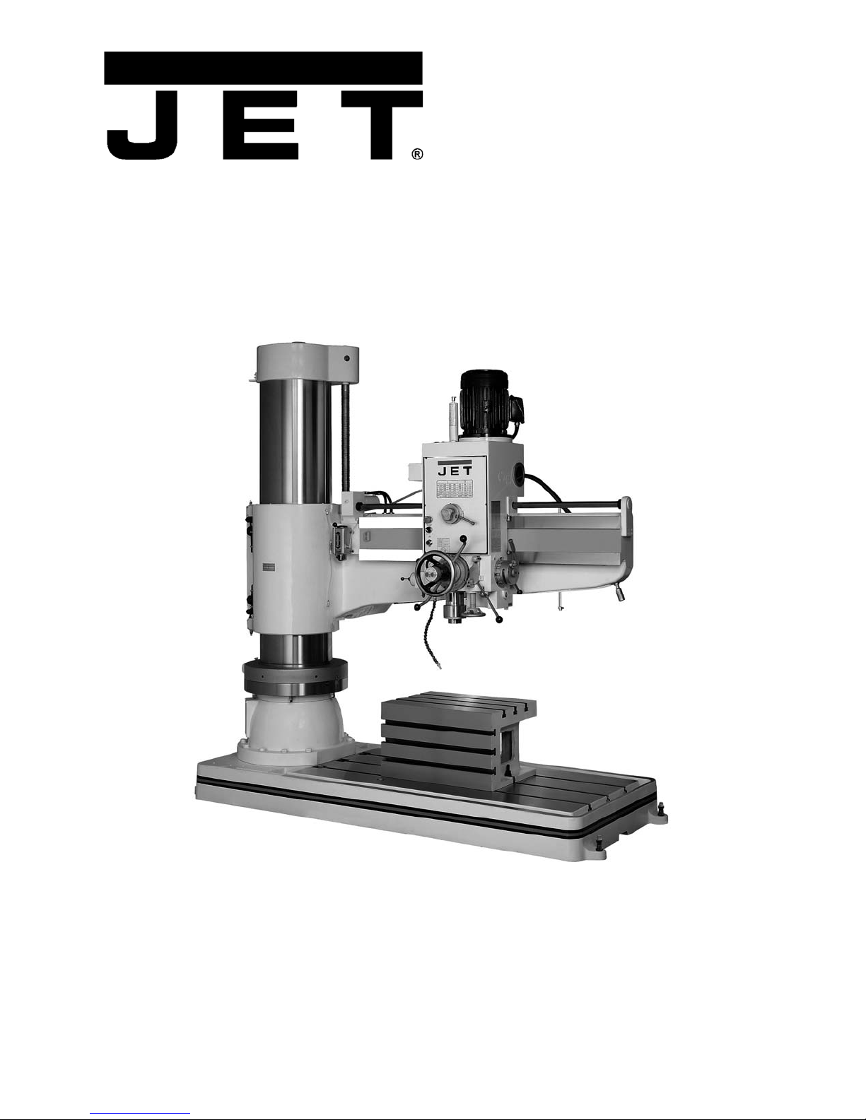
The JET Model J-1600R is a powerful and versatile radial arm drill press. The drill head is mounted on an arm
and can slide along the arm to position the spindle over the work piece. The arm itself can be rotated on its
support column to allow centering the spindle over the work piece.
Drilling can be performed manually or with power feed assistance. In addition, parameters of RPM, power feed
rate and drilling depth can be pre-set by the operator, using controls conveniently positioned on the drill head.
The drill has an automatic tool ejector, and hydraulic head and column clamping system.
The power train gears and spline shaft are made of high quality heat-treated and ground nickel chrome steel,
offering greater strength and smoothness to high-torque loads. The spindle is of case hardened steel and
supported by dual row taper roller and thrust ball bearings at the nose, with thrust and radial axis bearings at
the top. The frame is made of Meehanite® and high-tensile strength cast iron.
A precision machined box table allows convenient positioning and clamping of smaller work pieces. The box
table can be removed from the base to allow larger workpieces to be clamped on the base itself. Both table and
base have multiple T-slots for clamping set-ups.
Model number.......................................................................................................................................... J-1600R
(J-1600R-4 is the same machine but pre-wired for 460V operation)
Stock numbers:
J-1600R.................................................................................................................................................. 320038
J-1600R-4 .............................................................................................................................................. 320039
Head and Spindle:
Push button controls ..................................................................................................................................110V
Spindle motor (model J-1600R)......................................................... TEFC Induction, 7.5 HP (5.5 kW), 3 PH,
230/460V (pre-wired 230V), 19/9.5 A, 60Hz
Spindle motor (model J-1600R-4)...................................................... TEFC Induction, 7.5 HP (5.5 kW), 3 PH,
230/460V (pre-wired 460V), 19/9.5 A, 60Hz
Control circuits ...........................................................................................................................................115V
Spindle taper ..............................................................................................................................................MT-5
Spindle speeds..........................................................................................twelve speeds, within 40-1920 RPM
Quill (spindle) travel ............................................................................................................. 14-9/16” (370 mm)
Quill (spindle) travel with powerfeed engaged ............................................................................. 13” (330 mm)
Spindle travel along arm, total.............................................................................................. 44-7/8” (1140 mm)
Feed rates (distance per revolution) ..........................................................................six at 0.003 - 0.038 in/rev
Base surface to spindle, maximum (no tooling) ......................................................................... 63” (1600 mm)
Base surface to spindle, minimum (no tooling) ............................................................................ 15” (380 mm)
Column to spindle center distance, maximum ..................................................................... 62-1/4” (1580 mm)
Column to spindle center distance, minimum ......................................................................... 13-3/8” (334mm)
Noise emission (approx. 3-1/4 ft./1m from spindle head) * ..................... 82 dB at 1500 rpm; 79 dB at 88 RPM
Arm and Column:
Column diameter.......................................................................................................................... 17” (432 mm)
Arm vertical travel on column............................................................................................ 33-15/32”. (850 mm)
Arm elevating motor ....................................................TEFC, 2 HP (1.5 kW), 3 PH, 230/460V, 3.2/1.6A, 60Hz
Clamping motor..........................................................TEFC, 1 HP (0.75kW), 3 PH, 230/460V, 3.2/1.6A, 60Hz
Base and Table:
Box table dimensions ..........................................................27-1/2”L x 19-3/4”W x 16”H (700 x 500 x 415 mm)
T-slots in Table (6) ............................................................ 1-1/2”W x 3/4" D, 7/8” W opening (38 x 19, 22 mm)
Base dimensions..............................................................103-1/4”L x 40-1/4”W x 8”H (2623 x 1022 x 203mm)
T-slots in Base (3) .............................................................. 1-1/2”W x 3/4 D”, 7/8”W opening (38 x 19, 22 mm)
Additional specifications:
Coolant pump motor..................................................TEFC, 1/8 HP (0.1kW), 3 PH, 220/440V, 0.2/0.1A, 60Hz
Machine height (floor to motor at maximum elevation) ............................................................. 125” (3175mm)
Shipping Dimensions ..............................................................110”L x 57”W x 115”H(2794 x 1448 x 2921mm)
Net weight ........................................................................................................................... 11,000 lb / 4990 kg
Shipping weight................................................................................................................... 11,240 lb / 5098 kg
* Measured under test conditions SS41 material, 32mm thick, Ø32mm tool.

8
4.1 Machining Capacities
Drilling Tapping Boring
Mild Steel 2-1/2 in. (mm) 2” (mm) 5” (mm)
Cast iron 2-5/16 in. (58.75mm) 2-3/8” (mm) 7-3/8” (mm)
Table 2
4.2 Machine Environment
1. Do not position the machine where it receives direct sunlight.
2. Normal ambient temperature should be between +5°C (41°F) and 40°C (104°F).
3. Humidity: Between 30% and 95%. At maximum temperature of 40°C/104°F, relative humidity should not be
over 50%. Higher humidity is acceptable at relative lower temperatures (e.g. 90% humidity at 20C°).
4. Keep machine away from gasoline, chemical substances, dust, acid, sulfides, magnetic interference and
explosive environments.
5. Keep machine away from electrical interference sources such as welding machines and EDM (Electric
Discharge Machining).
6. Illumination of work area should be greater than 500lux.
7. Work area must have adequate ventilation.
8. Floor must be flat.
9. Keep floor around machine free of hydraulic splash to prevent hazard of slipping and falling.
4.3 Power Supply Requirements
1. Acceptable voltage fluctuation: normally +/- 10%
2. Acceptable frequency fluctuation: +/- 1Hz (50/60Hz)
3. Acceptable momentary power-off duration: less than 10m.sec
4. Acceptable voltage impulse:
Peak value: 200% or less than the line voltage of the actual value (rms.value).
Duration: 1.5m.sec or less.
5. Acceptable AC voltage of the waveform distortion.
6. Acceptable imbalance of the line voltage: 5% or less.
7. Power capacity:
Main motor: 5.625 Kw (7.5HP)
Arm elevating motor: 1.5kW (2HP)
Clamping motor: 0.75kW (1HP)
Coolant pump motor: 0.1kW (1/8HP)
Total power requirement: 20.203 KVA

9
4.4 Overall Dimensions, J-1600R
Figure 2
The specifications in this manual were current at time of publication, but because of our policy of continuous
improvement, Walter Meier reserves the right to change specifications at any time and without prior notice,
without incurring obligations.

10
5.0 General Features and Terminology, J-1600R
Figure 3
1. Column cover (encloses arm elevating motor)
2. Elevating lead screw
3. Column
4. Locking nuts
5. One shot lube unit
6. Machine identification plate
7. Column clamping indicators
8. Base
9. Box table
10. Coolant nozzle
11. Spindle
12. Work lamp
13. Arm rotation handle
14. Rack
15. Arm rail
16. Spindle speed chart
17. Sight glass (and clutch access)
18. Drill head/gearbox *
19. Spindle motor, 7-1/2HP
20. Leveling screws
21. Work lamp toggle switch
22. Support block (for shipping only)
23. Brace (for shipping only)
24. Coolant pump
25. Arm clamping cylinder
26. Guard panel
27. Electrical cabinet
28. Counterweight system
29. Hydraulic clamping motor, 1HP
30. Hydraulic tank
31. Pressure gauge
32. Solenoid valves
33. Clamping cylinder
34. Guide bar
*See Figure 10 for details on drill head controls.

11
General Features and Terminology, J-1600R (cont.)
Figure 4
Figure 5

12
6.0 Set-Up and Assembly
6.1 Floor Diagrams for J-1600R
Figure 6
Figure 6 shows spacing for the 360° rotational path of the arm, plus 1000mm (approx. 40 inches) of general
maintenance area on each side.
Distance column center to arm limi
t
Maintenance area (A) Total space required (B)
2087mm (82 in.) 1000mm (40 in.) 6174mm (243 in.
/
20-1/4 ft.)
Figure 7
(all dimensions in millimeters unless otherwise noted)

13
6.2 Unpacking
Remove any remnants of shipping crate and check
for shipping damage. Report any damage
immediately to your distributor and shipping agent.
Do not discard any shipping material until the
Radial Arm Drill Press is installed and running
properly.
Compare the contents of your container with the
following parts list to make sure all parts are intact.
Missing parts, if any, should be reported to your
distributor. Read the instruction manual thoroughly
for assembly, maintenance and safety instructions.
Contents of Shipping Container
(see Figure 8)
1 Radial Arm Drill Press (not shown)
6 Leveling Pads
1 Tool Box, containing:
1 Grease gun
1 Oil bottle
1 Tapered drift
1 Adjustable wrench
1 Set of hex keys
1 Flat blade screwdriver
1 Cross point screwdriver
1 Instructions and Parts Manual (not shown)
1 Warranty Card (not shown)
1 Manufacturer’s Test Chart (not shown)
Figure 8: Tools provided
Read and understand the entire contents of this manual before attempting set-up or
operation! Failure to comply may cause serious injury.

14
6.3 Machine Set-Up
1. After dismantling crate, remove toolbox and
any accessory items from around machine.
2. Place lifting straps as shown in Figure 9. Use
cushioning to protect machine surfaces.
Figure 9: Method of lifting
3. Remove the bolts holding machine to pallet.
All lifting equipment must
be rated appropriately to safely sustain
weight of drill press. Do not allow anyone
near or beneath machine while it is being
moved.
4. Lift machine and position it over anchor bolts
in an area with good lighting, and a level and
well-supported floor.
5. Place provided leveling pads beneath base,
using appropriate spacing. Place a level (its
tolerance should be within 0.02mm/m) on box
table and level the machine.
6. The drill press MUST be anchored to floor.
Use layout diagram in Section 6.1 as a guide,
and mount the nuts to the ground bolts.
Failure to anchor machine
properly, according to the diagrams, could
result in machine tipping over and
consequent damage to machine and
possible injury to machine operator and
bystanders.
7. Connect electrical service branch to machine
according to instructions which follow in
section 6.4, Electrical Connections. This work
should be done only by a qualified and
licensed electrician who is familiar with
machine service and national and local codes.
8. Turn on drill press (see section 8.0,
Operation), push the unlock button, and move
arm/spindle control lever to UP, until quill
clears the shipping block and the arm clears
the support brace. Remove shipping block and
wood platform from box table. Remove
shipping brace from base. (Retain these
support pieces if machine is to be transported
in future.)
9. Surfaces of the machine have been treated
with a protective coating for shipment; remove
this with mineral spirits or a cleaner/degreaser.
Then apply a light coating of oil to exposed
metal surfaces. See section 12.0 Maintenance,
for details.
10. Inspect all sight glasses on machine to be
certain they are filled to their level lines. If low,
add fluid as necessary according to
instructions in section 12.2 Lubrication.
11. Perform a lubrication check at all points
recommended in section 12.0.
Verify that the machine is
properly lubricated at all points before
operating.
12. Follow directions in section 8.0, Operation, to
check all operation functions of drill press. If
coolant is being used, put coolant in the sump
and test coolant delivery.
13. When all of the above operations are
complete, the machine is ready for service.

15
6.4 Electrical Connections
Electrical set-up should be
performed only by a licensed electrician who is
familiar with national and local electrical codes.
This machine must be properly grounded to
help prevent electrical shock and possible fatal
injury.
Model J-1600R radial drills are tested before
shipping for all functions and circuits under
electrical power specified for the machine and
motors. The only hook-up requirement should be
for correct connection to an appropriate cutout on
an appropriate service branch.
Where the following instructions do not agree with
local electrical codes and procedures, the
applicable codes and procedures should be
followed, exclusively.
Wiring diagram
A wiring diagram for the drill press is found inside
the door of the electrical cabinet. A similar diagram
is shown in back of this manual. This diagram is for
reference by your licensed installing or servicing
electrician.
All three motors on the J-1600R are 3-phase
motors of the same voltage value. All control
circuits are 110 volt circuits. The motor’s circuit is
NOT fused. Thus, fuses for each leg of the 3-
phase service branch must be supplied by the
installing electrician. If a service disconnect with
a fuse for each leg of the 3-phase branch is not
supplied, then none of the motors are protected
from electrical faults.
In addition to using a licensed electrician for
connection to the drill press service branch, the
servicing of components and circuits inside the
control box should be serviced only by a qualified
electrician. This includes fuse replacement, if
required. If any of these fuses, upon replacement,
should continue to fail at short service intervals, the
electrician should be asked to check all machine
components for excessive loads, short circuits or
other failures.
Electrical branch service
The machine is wired for either a 230V or 460V, 3-
phase service branch. The cable supplying the drill
press will be tagged with the voltage at which the
machine was tested and corresponding to the
customer's order.
If the tag has been lost, it will be necessary for you
to open the electrical cabinet on the rear of the drill
press and examine the connections on the
transformer found inside the box. The transformer
can be connected to either a 230 or 460 volt
source and its taps are labeled for voltage. By
locating the source tap on the transformer you will
be able to determine the branch voltage required.
A service disconnect is recommended. The use of
fuses or circuit breakers for each of the voltage
supply wires is required. Use fuses or circuit
breakers which are appropriate to the voltage for
the motor system delivered.
A positive cut-out/lock-out lever or rocker switch
should be located on the outside of the service
disconnect to allow the machine operator to
disconnect from the branch circuit when working
with tooling on the machine.
It is recommended that the 230 volt Drill Press be
connected to a dedicated 25 amp circuit with a 25
amp circuit breaker or time delay fuse. Connect the
460 volt drill press to a dedicated, 15 amp circuit
with 15 amp circuit breaker or time delay fuse.
Local codes take precedence over recommen-
dations.
Connecting branch to drill press
1. Disconnect service branch to machine by
moving lever or rocker switch on cutout box to
OFF.
2. Connect the green wire (or green with white
trace) to the branch ground.
3. Connect the remaining three wires in the cable
(labeled R, S and T) to the three power lines in
the branch.
4. Turn power to the machine ON at the cutout
box.
5. Turn coolant switch (See Figure 10) to ON
position.
Make sure there is coolant
in flood coolant system before operating
pump. Failure to comply may cause
damage to pump.
6. Observe rotation through glass atop pump.
The shaft should be rotating in direction of
arrow cast into pump assembly. If shaft is
rotating wrong direction, the power leads need
to be switched. Correct as follows:
7. Disconnect power to machine by turning it off
at cutout box.
8. Reverse any two of the power lead
connections, R, S or T.
9. Repeat steps 4, 5, and 6, above, and you
should observe pump shaft turning in proper
direction. Electrical service to machine is now
complete.

16
7.0 Operating Controls
Figure 10: Operating Controls

17
8.0 Operation
8.1 Clamping workpieces
To load/unload heavier workpieces, unlock arm
and rotate it out of the way. Lift the workpiece with
slings or other properly rated lifting equipment.
Both the box table and base surface are slotted to
accept a suitably sized T-slot clamp. Before
beginning any work on the drill press, anchor the
work piece, and box table if used, to be certain that
workpiece and/or box table will not move when tool
enters workpiece.
If box table will not be used, simply remove the
nuts at the base, and move table off using proper
lifting equipment.
Failure to properly anchor
workpiece and box table could result in
damage to machine, damage to workpiece, and
severe injury to machine operator. Never work
on drill press without clamping the materials
using a T-slot system set-up.
8.2 Tool insertion
The Model J-1600R uses a No. 5 Morse taper in
the spindle to secure tooling. Any drill, milling
cutter, or tool holder with an MT-5 can be inserted
into the quill.
The first step in removing or
inserting any tooling is to be absolutely certain
the machine cannot be accidentally started
during the insertion or removal operation. The
only way to be certain of this fact is to disconnect
power to machine. The service box should have a
cut-out switch or lever on the outside of the box.
Position switch or lever in the OFF position before
inserting or removing tooling.
To insert tooling:
1. Verify that machine is disconnected from
power.
2. Be certain the spindle is clean, free from oil,
and ready to accept the shank of any tooling.
3. Check the shank of tooling to be certain the
tooling is free from dirt, nicks or burrs. If nicks
or burrs are discovered, file or stone the shank
until it is smooth.
4. Pull the tooling ejection handle out to be
certain the tooling can be inserted. See Figure
10.
5. Be certain quill is in full UP position.
6. Slide shank of tooling into spindle until it seats.
7. Use a soft-faced mallet (such as lead, plastic,
brass, etc.) to give the tooling a sharp tap on
its tip. This will secure the tooling in the taper.
8. Re-establish power to machine, and the drill is
ready to use.
To remove tooling:
9. Verify that machine is disconnected from
power.
10. Place a wood block under the tooling in
spindle, to prevent it being damaged should it
fall out during the removal process.
11. Use the feed levers to lower quill enough to
allow tooling ejection handle to be pushed fully
inward.
12. While using leather gloves to hold the tooling
and prevent it from falling loosely out of the
spindle taper, use the feed levers to give the
quill a sharp upward stroke against the top of
its travel and the tooling will be released from
the taper in the spindle.
13. Remove tooling and pull tooling ejection
handle out to allow new tooling to be inserted.
8.3 Tool positioning over workpiece
After workpiece has been clamped to base or
table, position the tooling over workpiece, using
any or all of the following methods:
1. Adjusting height of arm on support column.
2. Moving drill head along arm.
3. Rotating column upon which arm and head are
attached.
8.4 Unlocking arm and column
mechanisms
A motorized locking system is used to lock the
head to the arm, the arm to the column, and the
column to the base.
The buttons which control the locks are located in
center of drill head handwheel (see Figure 10).
Press and hold UNLOCK (green) button until arrow
(Figure 11) points to “B”. Release button. Clamping
device is now disengaged. When locking, press
and hold LOCK (red) button until arrow points to
“A”. Clamping device is now re-engaged.
NOTE: When you push UNLOCK, all of the locks
are disengaged. When you push LOCK, all of the
locks are engaged.
Always be certain the locks
are engaged before using drill press. Pull on
arm handle and try to rotate handwheel at front
of head, before starting spindle. Failure to have
all locks secure may result in damage to
tooling, damage to workpiece, and possible
injury to operator.

18
Figure 11: Locking indicators
8.5 Raising and lowering radial arm
1. Power to drill press must be ON – then release
machine locks by pushing UNLOCK button in
center of handwheel.
2. Raise or lower arm to required height using
arm/spindle control lever (see Figure 10). See
also section 8.24, Arm/spindle control lever.
3. When arm is at required height and if no other
adjustments to spindle location are required,
press LOCK button to engage all machine
locks.
8.6 Moving drill head along arm
1. Power to drill press must be ON – then release
machine locks by pushing UNLOCK button.
2. Turn handwheel to move drill head along arm.
See Figure 10.
3. When drill head is at desired position on arm
and if no other adjustments to spindle location
are required, push LOCK button to engage all
machine locks.
NEVER swing drill press arm
on support column unless you are absolutely
certain the drill press base is firmly attached to
shop floor. You can tell if base is bolted to floor by
checking the mounting pads at the four corners of
base. There should be a securing bolt through
each mounting pad. If the arm is moved off its
position directly above base and base is not bolted
to floor, THE DRILL MAY TIP OVER AND CAUSE
SERIOUS INJURY TO THE DRILL PRESS
OPERATOR, and will certainly result in damage to
drill press itself.
8.7 Rotating arm on support column
1. Power to drill press must be ON – then release
machine locks by pushing UNLOCK button on
front of handwheel.
2. Swing arm using handle (see Figure 10) to
required spindle position.
3. When spindle is positioned correctly and no
other adjustments are required, push LOCK
button to engage all machine locks.
8.8 Setting spindle speed
Spindle speeds are established using gear change
levers on lower right-hand side of drill head. The
shorter of the two levers (C, Figure 12) operates a
two-speed mechanism which puts the gearbox in
either high or low gear. The longer gear change
lever (D) operates a three speed gearbox
mechanism. A detent in the middle of the three-
speed lever travel indicates when lever is in
intermediate gear position.
The spindle speed readout (F) is located on the
three-speed change mechanism housing.
Figure 12: Gear change levers
This gearbox set-up allows a total of six spindle
speeds which may be selected. Adding the two
speeds possible with the HI/LOW change lever (E,
Figure 12) increases the number of available
speeds to twelve.
A chart on front of drill head shows gear change
values required to select each speed. A similar
chart is included in Table 4 of this manual.
Also on the spindle speed chart are recommended
drill and tap sizes for the various speeds which are
selectable. These recommendations are only
approximate. With the wide variety of drill types
and coatings available, as well as cutting fluids,
and the even wider variety of workpiece materials
which you might be machining – you need to
consult with your tooling, coolant and/or workpiece
suppliers to determine best spindle speed to use
for any specific drilling operation.

19
Do not try to change gears
while spindle is turning. This may cause
serious damage to spindle drive system.
To select spindle speed:
1. Allow spindle to stop rotating.
2. Press emergency stop button.
3. Move short lever (C, Figure 12) to position “1”
or “2”.
4. Move long lever (D) to appropriate position. (If
lever C is in position “1”, refer to arrow marker
“1” for the reading. If lever C is in position “2”
refer to arrow marker “2” for correct reading.)
5. Move HI/LOW change lever (E) to desired
position. When this lever is in HI setting, use
the red numbers on the spindle speed readout
(F). When this gear is in LOW setting, use the
black numbers on the spindle speed readout.
Note: An instruction plate is located near the gear
change levers for quick reference to this
procedure.
Allow spindle to stop completely before attempting
to change gears. If gear change lever you want to
move does not slip easily into new position, jog the
motor for a second using the control lever. Then
allow spindle to come to a stop before attempting
to change gears again. Repeat this jogging
process, as necessary, until gears match up
properly for changing.
Plan for quill movement if
selecting high speed spindle rotation. High
speed rotation without quill travel will increase
spindle temperatures.
8.9 Feed rate and depth of cut
The J-1600R has limit switches on the quill which
cut power to drive motor when quill has reached
either upper or lower limit of its travel. This system
is designed to prevent gearbox damage if power
feed mechanism is engaged – damage which
would occur if quill were to bottom out against
upper or lower limit of quill travel. In the event of
failure of either limit switch there is also a safety
clutch mechanism which will slip when travel limits
are reached.
However, while you are able to use virtually full
travel of the quill for drilling or other operations, the
drill press operator typically sets both rate of feed
(travel-per-revolution of spindle), and depth of cut
(quill travel to make required cut).
These two operations are described here:
8.10 Setting feed rate
The feed rate is set using dial/lever combination on
front of drill head. See Figure 13. The dial can be
rotated to select different feed rates, and the lever
can be moved to two positions, thus providing six
different feed rates. The selected rate is displayed
in the readout window on the dial.
Figure 13: Feed rate setting mechanism
Any of three feed rates are available for selection
using any of the spindle speeds available. There
will be a recommended feed rate for any drilling or
boring operation, and this rate must be determined
by consulting appropriate machinery handbooks or
by consulting with your tooling, coolant and
workpiece suppliers.
8.11 Feed methods
The J-1600R has three feed methods: power feed,
hand feed and fine hand feed. When using the
power feed system it is possible to establish a pre-
set depth of cut.
8.12 Setting depth of cut using
power feed system
There is a mechanism for engaging power feed
and there is also a “trip” mechanism which can be
set to disengage power feed when a pre-set depth
has been reached.
1. Set feed rate according to instructions in
section 8.10; Setting feed rate.
2. Set spindle speed appropriate to desired cut
(section 8.8; Setting spindle speed).
3. Push power feed engagement lever to left to
engage power feed system.
4. Turn power switch to ON.
5. Move spindle/arm control lever to required
spindle rotation direction.
6. Pull feed levers outward, away from drill head,
to engage power feed clutch. In this power
feed position, quill and spindle will be driven
until one of the following happens:
•Spindle reaches limit of travel and the limit
switches disable power; or
•The “trip” mechanism automatically
disengages power feed; or
•Drill press operator pushes feed levers
into disengaged position; or

20
•Drill press operator pulls power feed
engagement lever into disengaged
(toward right) position.
To set depth of cut for power feeding:
Refer to Figure 14.
1. Unlock both levers (A, Figure 14).
2. Rotate feed levers (B) to lower drill until it
touches workpiece.
3. Rotate dial (C) until required feed depth on
scale is at zero reference mark (D).
4. Lock both levers (A).
5. Push power feed engagement lever (F) toward
the left.
6. Pull feed levers (B) out to engage power feed
clutch. The power feed mechanism will feed
drill into workpiece at the rate selected on feed
rate dial, until selected depth of cut is
complete.
Note: The depth limit for power feed drilling is
4.0 inches (100mm). If deeper holes are
needed, the machining must be done in steps.
IMPORTANT: Feed rate must be set (out of neutral
position) before power feed can be engaged.
Figure 14: Depth setting; power feed engagement
8.13 Spindle direction and power
feed
Spindle rotation direction is managed by the
arm/spindle control lever on left side of drill head.
See Figure 15.
Figure 15: Spindle/arm control lever
Clockwise or "forward" rotation is the direction of
rotation for right-hand tooling – the vast majority of
tooling used in machine operations. Reverse
spindle rotation for left hand tooling.
Power feed direction is determined by the spindle
direction. When spindle is set to its most common
direction – clockwise or forward – the quill and
spindle are driven downward. When spindle
direction is set counterclockwise (reverse), quill
and spindle are driven upward.
8.14 Hand feed – roughing
operations
When the feed levers are pushed toward the drill
head the power feed mechanism is disengaged. In
this position, the feed levers can be used to move
the quill and spindle and perform manual drilling or
other machining operations.
8.15 Fine hand feed using power
feed system
The fine feed handwheel is located on underside of
front of drill head. See Figure 10. The fine feed
control is used as follows:
1. Set feed rate lever to far right to disengage.
2. Pull feed levers out to engage power feed
clutch.
3. Turn drill press power switch to ON, and set
arm/spindle control lever to desired direction.
4. Manually turn fine feed handwheel. Quill and
spindle will move downward or upward
(depending upon which way you turn
handwheel and the direction spindle is turning)
until you stop turning the handwheel.
8.16 Tapping
1. Insert screw tap into spindle.
2. Move spindle into position.
3. Set spindle control to Forward.
4. Rotate feed levers counterclockwise until
desired tapping depth is reached.
5. Reverse spindle direction and allow tap to
withdraw completely from workpiece.
6. Stop spindle by moving spindle control switch
to center (neutral).
8.17 Power ON/OFF
If your J-1600R was connected to its service
branch correctly, there will be a service disconnect
with an external power cutoff lever or switch which
disconnects the drill press from the service branch.
This is your ultimate protection against accidental
machine start-up when clamping work pieces or
inserting and removing tooling. Always be certain
This manual suits for next models
1
Table of contents
Other Jet Power Tools manuals
Popular Power Tools manuals by other brands

Aimco
Aimco AcraDyne HT ABG Series Operation and service manual

BorMann
BorMann Technik BAI2500 owner's manual

Enarco
Enarco VIB-BAR E-BATT instruction manual

Bosch
Bosch 1507 - Tool 10 Gauge Unishear Shear Operating/safety instructions

Milwaukee
Milwaukee M18 PROPEX 2632-20 Operator's manual

Makita
Makita 6934 instruction manual