Jet HBS-1321W WMH Service manual

Operating Instructions and Parts Manual
Semi-Automatic Band Saw
Model HBS-1321W
WALTER MEIER (Manufacturing) Inc.
427 New Sanford Road
LaVergne, Tennessee 37086 Part No. M-414471
Ph.: 800-274-6848 Revision G2 01/2012
www.waltermeier.com Copyright © 2012 Walter Meier (Manufacturing) Inc.

2
Warranty and Service
Walter Meier (Manufacturing) Inc., warrants every product it sells. If one of our tools needs service or repair, one of
our Authorized Service Centers located throughout the United States can give you quick service. In most cases, any
of these Walter Meier Authorized Service Centers can authorize warranty repair, assist you in obtaining parts, or
perform routine maintenance and major repair on your JET® tools. For the name of an Authorized Service Center in
your area call 1-800-274-6848.
MORE INFORMATION
Walter Meier is consistently adding new products to the line. For complete, up-to-date product information, check with
your local Walter Meier distributor, or visit waltermeier.com.
WARRANTY
JET products carry a limited warranty which varies in duration based upon the product (MW = Metalworking, WW =
Woodworking).
WHAT IS COVERED?
This warranty covers any defects in workmanship or materials subject to the exceptions stated below. Cutting tools,
abrasives and other consumables are excluded from warranty coverage.
WHO IS COVERED?
This warranty covers only the initial purchaser of the product.
WHAT IS THE PERIOD OF COVERAGE?
The general JET warranty lasts for the time period specified in the product literature of each product.
WHAT IS NOT COVERED?
Five Year Warranties do not cover woodworking (WW) products used for commercial, industrial or educational
purposes. Woodworking products with Five Year Warranties that are used for commercial, industrial or education
purposes revert to a One Year Warranty. This warranty does not cover defects due directly or indirectly to misuse,
abuse, negligence or accidents, normal wear-and-tear, improper repair or alterations, or lack of maintenance.
HOW TO GET SERVICE
The product or part must be returned for examination, postage prepaid, to a location designated by us. For the name
of the location nearest you, please call 1-800-274-6848.
You must provide proof of initial purchase date and an explanation of the complaint must accompany the
merchandise. If our inspection discloses a defect, we will repair or replace the product, or refund the purchase price,
at our option. We will return the repaired product or replacement at our expense unless it is determined by us that
there is no defect, or that the defect resulted from causes not within the scope of our warranty in which case we will,
at your direction, dispose of or return the product. In the event you choose to have the product returned, you will be
responsible for the shipping and handling costs of the return.
HOW STATE LAW APPLIES
This warranty gives you specific legal rights; you may also have other rights which vary from state to state.
LIMITATIONS ON THIS WARRANTY
WALTER MEIER (MANUFACTURING) INC., LIMITS ALL IMPLIED WARRANTIES TO THE PERIOD OF THE
LIMITED WARRANTY FOR EACH PRODUCT. EXCEPT AS STATED HEREIN, ANY IMPLIED WARRANTIES OR
MERCHANTABILITY AND FITNESS ARE EXCLUDED. SOME STATES DO NOT ALLOW LIMITATIONS ON HOW
LONG THE IMPLIED WARRANTY LASTS, SO THE ABOVE LIMITATION MAY NOT APPLY TO YOU.
WALTER MEIER SHALL IN NO EVENT BE LIABLE FOR DEATH, INJURIES TO PERSONS OR PROPERTY, OR
FOR INCIDENTAL, CONTINGENT, SPECIAL, OR CONSEQUENTIAL DAMAGES ARISING FROM THE USE OF
OUR PRODUCTS. SOME STATES DO NOT ALLOW THE EXCLUSION OR LIMITATION OF INCIDENTAL OR
CONSEQUENTIAL DAMAGES, SO THE ABOVE LIMITATION OR EXCLUSION MAY NOT APPLY TO YOU.
Walter Meier sells through distributors only. The specifications in Walter Meier catalogs are given as general
information and are not binding. Members of Walter Meier reserve the right to effect at any time, without prior notice,
those alterations to parts, fittings, and accessory equipment which they may deem necessary for any reason
whatsoever. JET® branded products are not sold in Canada by Walter Meier.

WARNING
•Read and understand the entire instruction manual before attempting assembly or operation.
•All JET bandsaws are designed and intended for use by properly trained and experienced
personnel only. If you are not familiar with the proper and safe operation of a bandsaw, do
not use until proper training and knowledge have been obtained.
•Always wear approved safety glasses/face shields while using this machine.
•Make certain the machine is properly grounded.
•Before operating the machine, remove tie, rings, watches, other jewelry, and roll up sleeves above
the elbows. Remove all loose clothing and confine long hair. Do NOT wear gloves.
•Keep the floor around the machine clean and free of scrap material, oil and grease.
•Keep machine guards in place at all times when the machine is in use. If removed for maintenance
purposes, use extreme caution and replace the guards immediately.
•Do NOT over reach. Maintain a balanced stance at all times so that you do not fall or lean against
blades or other moving parts.
•Make all machine adjustments or maintenance with the machine unplugged from the power source.
•Use the right tool. Don't force a tool or attachment to do a job which it was not designed for.
•Replace warning labels if they become obscured or removed.
•Make certain the motor switch is in the OFF position before connecting the machine to the power
supply.
•Give your work undivided attention. Looking around, carrying on a conversation, and "horse-play"
are careless acts that can result in serious injury.
•Keep visitors a safe distance from the work area.
•Use recommended accessories; improper accessories may be hazardous.
•Make a habit of checking to see that keys and adjusting wrenches are removed before turning on the
machine.
•Always keep hands and fingers away from the blade when the machine is running.
•Never hand hold the material. Always use the vise and clamp it securely.
•Keep belt guard, blade guards, and wheel covers in place and in working order.
•Always provide adequate support for long and heavy material.
•Use a sharp blade and keep machine clean for best and safest performance.
•Failure to comply with all of these warnings may cause serious injury.
•Some dust created by power sanding, sawing, grinding, drilling and other construction activities
contain chemicals known to cause cancer, birth defects or other reproductive harm. Some examples
of these chemicals are:
Lead from lead based paint.
Crystalline silica from bricks, cement and other masonry products.
Arsenic and chromium from chemically treated lumber.
Your risk of exposure varies, depending on how often you do this type of work. To reduce your
exposure to these chemicals, work in a well-ventilated area and work with approved safety
equipment, such as face or dust masks that are specifically designed to filter out microscopic
particles.

4
Specifications:
Model: HBS-1321W
Stock Number....................................................................................................................414471
Capacity:
Round at 90°(in).................................................................................................13” (330 mm)
Round at 45°(in)...........................................................................................10-1/2” (268 mm)
Rectangle at 90°(in)...............................10” x 21” (254x533 mm) and 13” x 19” (330x483 mm)
Rectangle at 45°(in)................................................................11-1/2” x 10-1/2” (292x268 mm)
Throat Depth (in)......................................................................................................13” (330 mm)
Blade Size (in)...................................................1-1/4” x 0.042” x 161-1/2” (31.75x1.07x4102 mm)
Blade Wheel Diameter (in)........................................................................................18” (457 mm)
Blade Speeds (SFPM)........................................................................................................80-260
Floor Space Required (in).................................................................84” x 32-1/2” (2134x826 mm)
Bed Height (in).........................................................................................................32” (813 mm)
Motor..................................................................................3 HP, 3 PH, 230/460 (Prewired 230V)
Coolant Motor.....................................................................................................................1/6 HP
Net Weight (approx.)........................................................................................... 1,276 lb (579 kg)
Table of Contents
Warranty .....................................................................................................................................2
Warnings.....................................................................................................................................3
Specifications..............................................................................................................................4
Table of Contents........................................................................................................................4
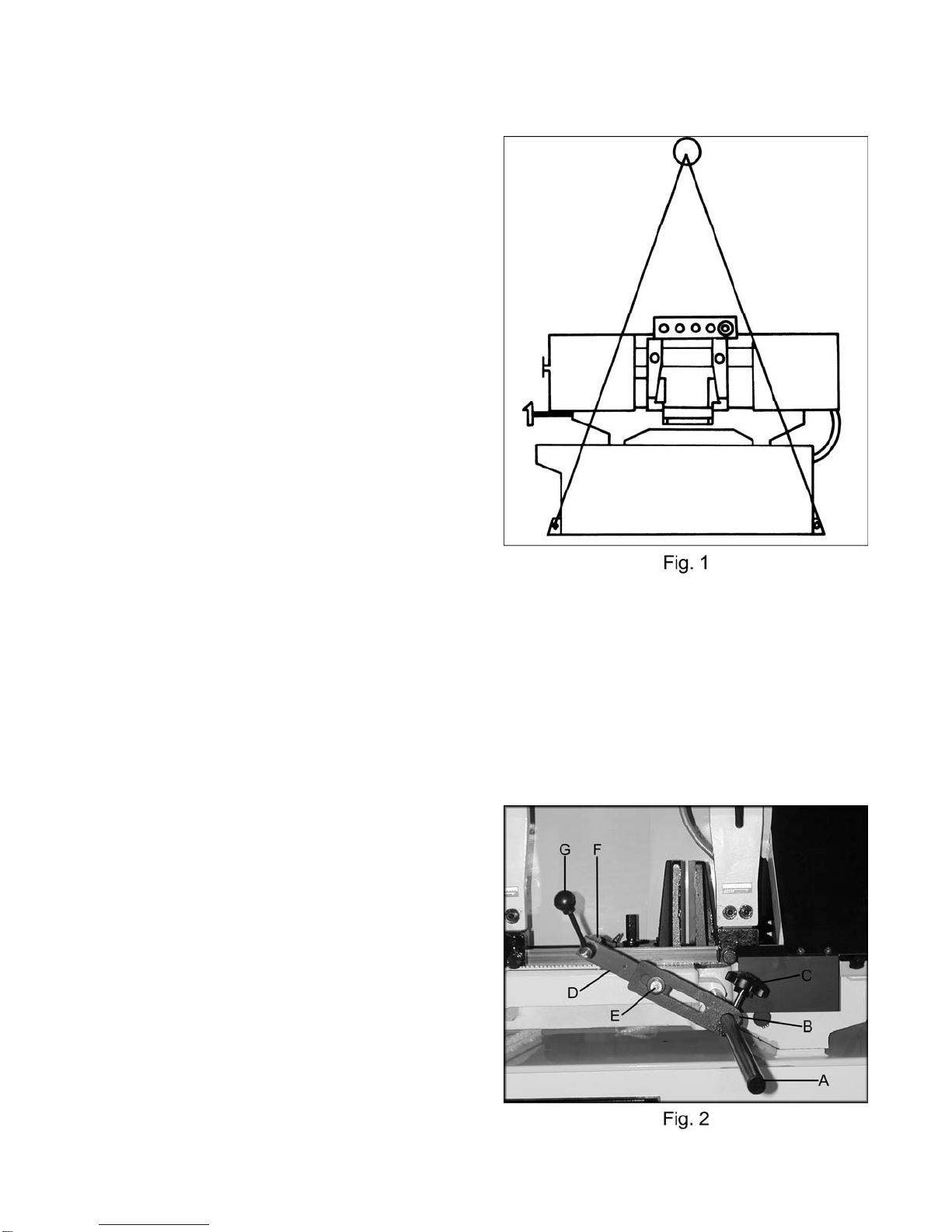
Uncrating and Cleanup................................................................................................................5
Installation...................................................................................................................................5
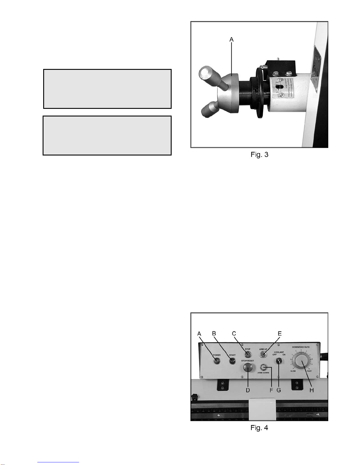
Assembly .................................................................................................................................5-6
Electrical Connections.................................................................................................................6
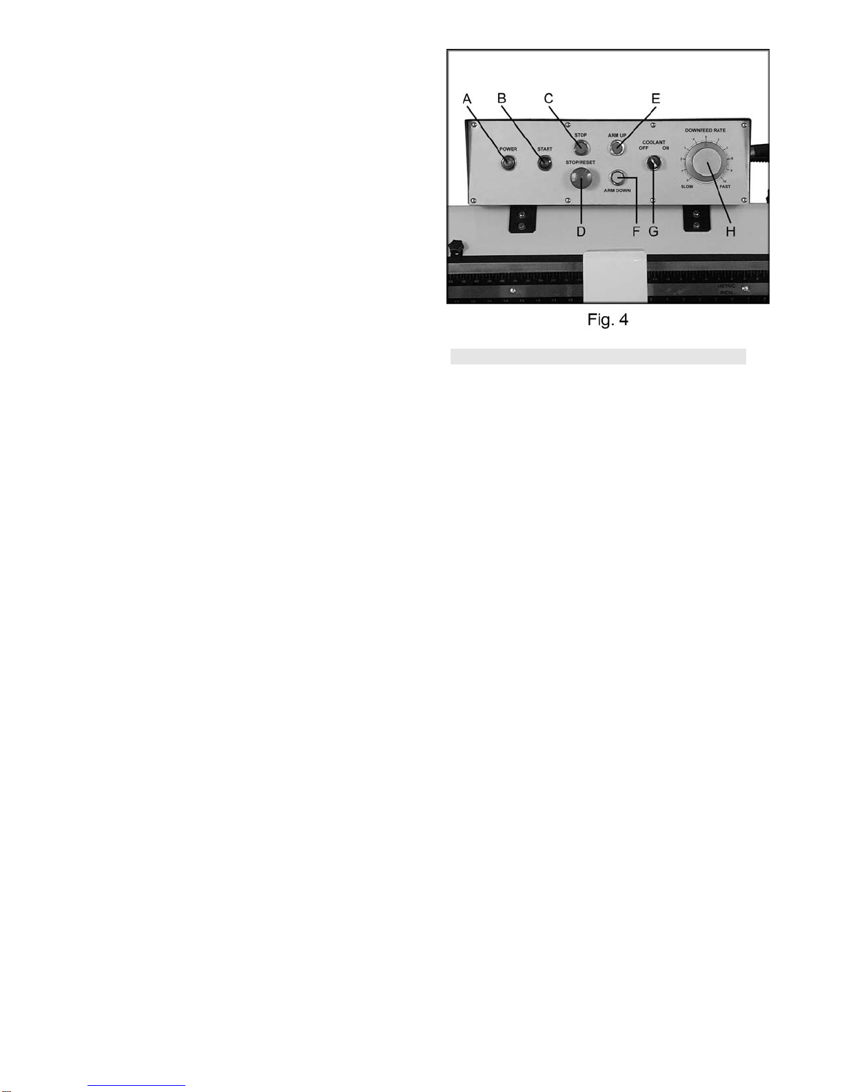
Controls....................................................................................................................................6-7
Prior To Operation.......................................................................................................................7
Adjusting Vise Square to Blade....................................................................................................8
Adjusting Vise for Miter Cuts........................................................................................................8
Positioning Vise...........................................................................................................................8
Changing Blade Speeds..............................................................................................................9
Semi Automatic Arm....................................................................................................................9
Automatic Shut Off ......................................................................................................................9
Adjusting Feed Rate....................................................................................................................9
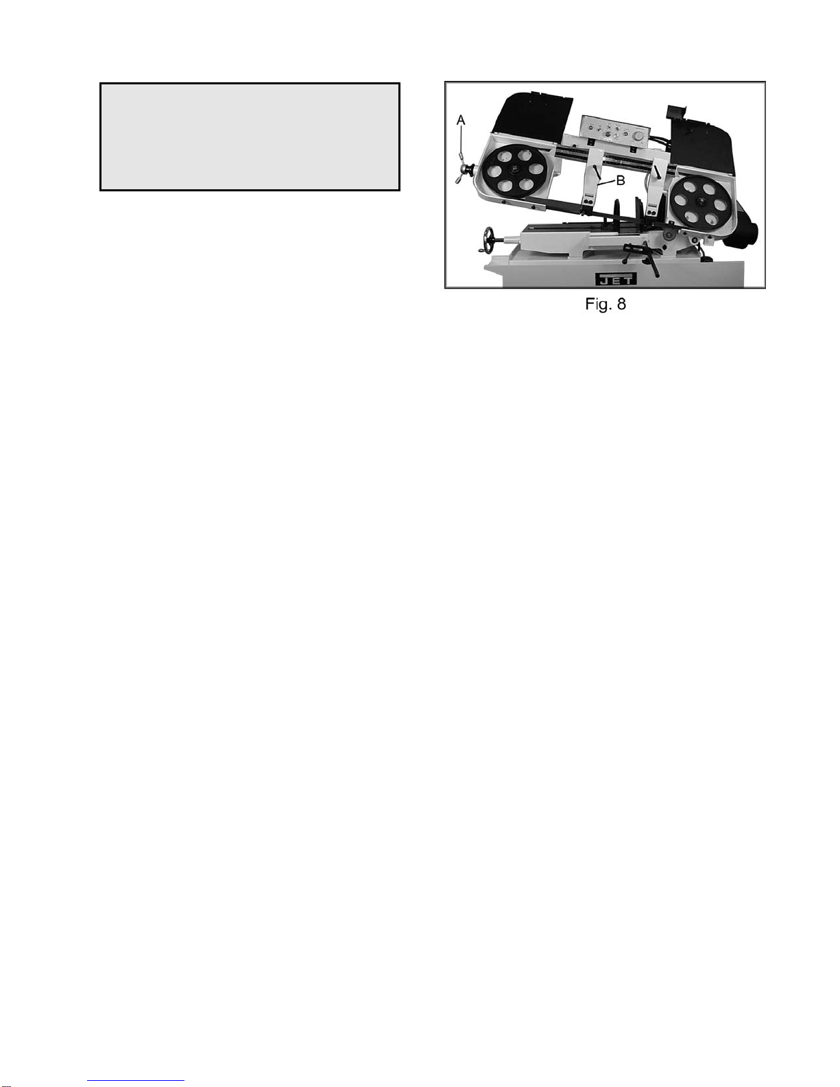
Changing Blades.......................................................................................................................10
Guide Roller Adjustment............................................................................................................11
Blade Guide Adjustment............................................................................................................11
Blade Tracking Adjustment........................................................................................................12
Lubrication & Gearbox..........................................................................................................12-13
Hydraulic Pump.........................................................................................................................13
Coolant Pump............................................................................................................................13
Replacing Variable Speed Belt ..................................................................................................13
Bed and Base Assembly Breakdown & Parts List..................................................................14-17
Arm Assembly Breakdown & Parts List.................................................................................18-22
Gearbox Assembly Breakdown & Parts List...............................................................................22
Wiring Diagram and Symbols................................................................................................23-24
The specifications in this manual are given as general information and are not binding. Walter Meier
(Manufacturing) Inc., reserves the right to effect, at any time and without prior notice, changes or
alterations to parts, fittings, and accessory equipment deemed necessary for any reason whatsoever.

5
Uncrating and Cleanup
1. Read and understand the entire manual
before attempting setup or operation.
2. Finish uncrating the saw and inspect for
damage. If any damage has occurred,
contact your local distributor.
3. Remove all bolts attaching machine to
shipping base.
4. Leave packing material between vice
clamps and saw head intact until bandsaw
has been lifted to its final position.
5. Clean all rust protected surfaces with
kerosene or diesel oil to remove protective
coating. Do not use gasoline, paint thinner,
mineral spirits, etc. These may damage
painted surfaces.
6. Lubricate all slideways with a light film of
Mobil DTE®Oil Heavy Medium.
Installation
For best performance, the bandsaw should be
located on a solid and level foundation. Allow
room for servicing and for moving large stock
around the bandsaw when deciding a location
for the machine.
1. Using lifting straps of adequate lifting
capacity, that are isolated from the
bandsaw's finished surfaces, lift machine
and place in desired location. See Figure 1
for strap placement.
2. Install four leveling bolts with lock nuts on
both sides of the base.
3. Place a level on the bed surface and check
side to side and front to back.
4. Adjust leveling screws until machine is level
in both directions and tighten locking nuts.
Assembly
1. Insert stop rod (A, Fig. 2) into the base
below the vise. Place stop bracket (B, Fig.
2) onto stop rod and tighten lock knob (C,
Fig. 2). Attach the connecting plate (D, Fig.
2) to stop bracket with hex cap bolt and
washer (E, Fig. 2), and tighten. Attach the
work stop (F, Fig. 2) to the connecting plate
with lock handle (G, Fig. 2), and tighten.
Other manuals for HBS-1321W WMH
1
Table of contents
Other Jet Saw manuals