TFP2272
Page 7 of 10
Installation
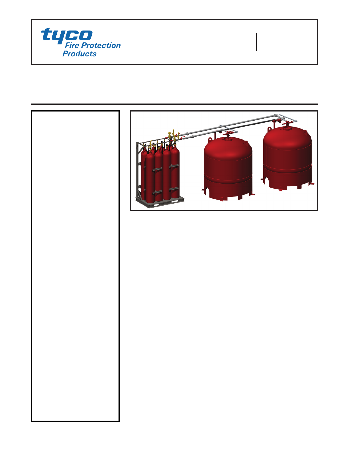
The TYCO AQUAMIST Red-E Mist
Supply Skid must be installed in accor-
dance with this section. For success-
ful performance, the entire Red-E Mist
Supply Skid must be installed in a loca-
tion within a temperature range of 40°F
to 130°F (4°C to 54°C).
NOTE: The following items are not
included when purchasing the AQUA-
MIST Red-E Mist Supply Skid and must
be purchased separately:
• 1-1/2 Inch Nitrogen Discharge Piping
• 1-1/2 Inch Water Discharge Piping
• Nitrogen Drain
• 1-1/2 Inch Wye connector (required
in 1200 Gallon (4542 Liter) systems)
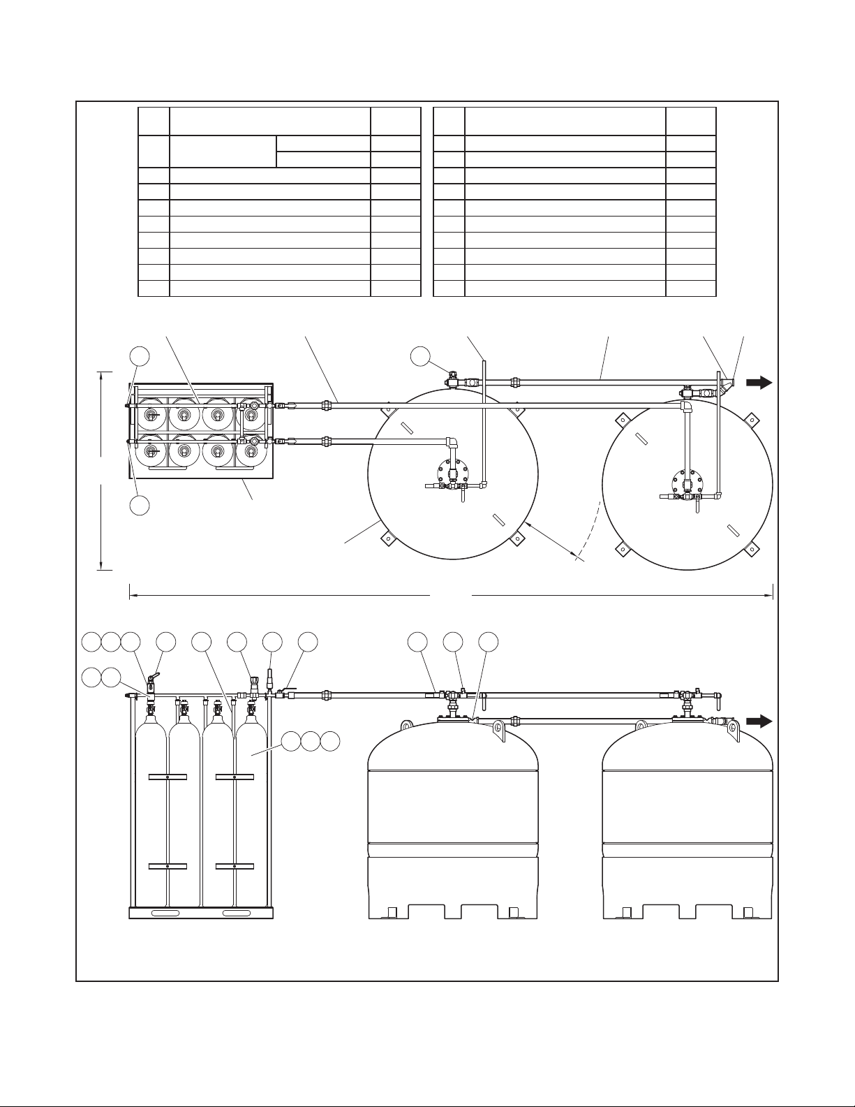
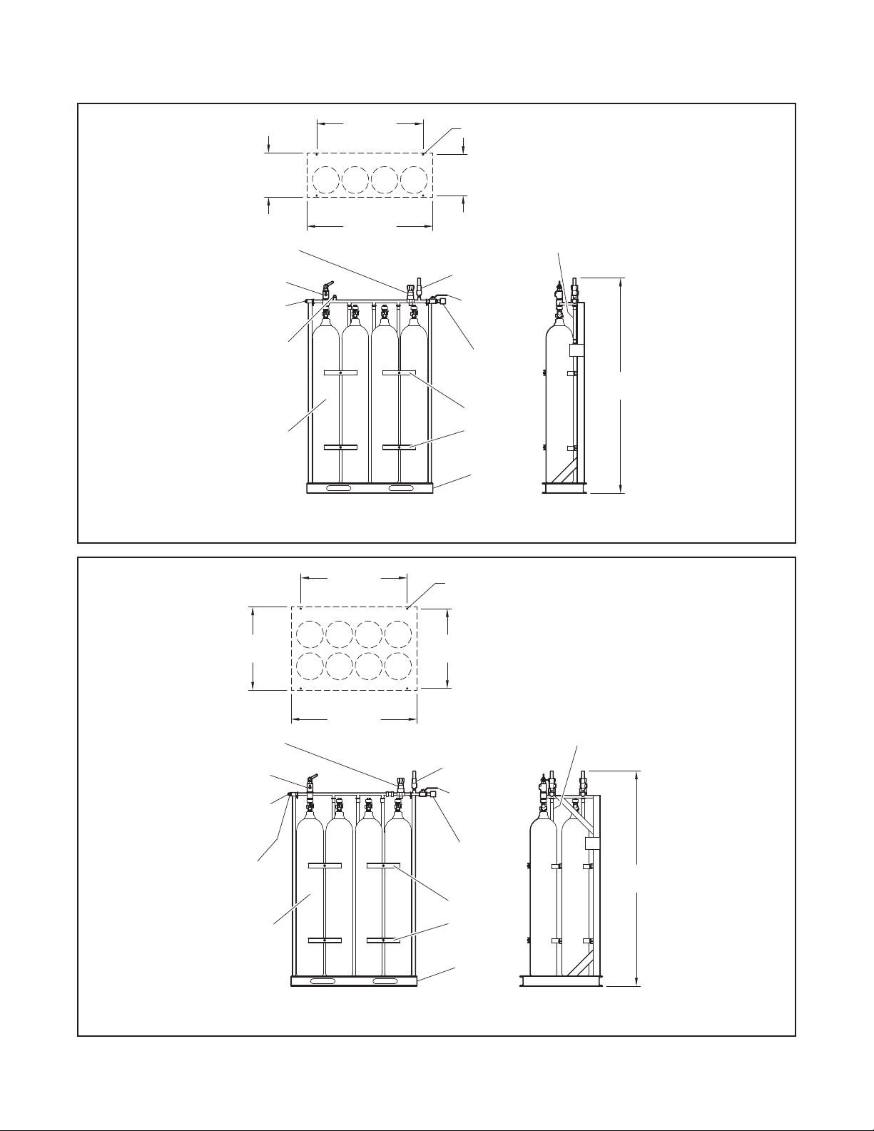
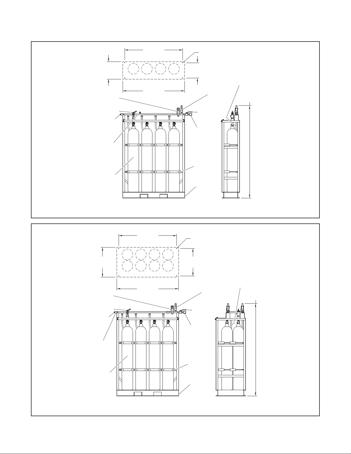
Nitrogen Supply Skid
The Nitrogen Supply Skid should
be located in an area with adequate
space to ensure access to all service-
able components. The skid must be
securely mounted or otherwise fas-
tened on a smooth, level, hard surface
capable of supporting the full weight
of the unit.
The weight of a 4 cylinder Nitrogen
Supply Skid is 1360 lbs. (617 kg) and
the weight of an 8 cylinder Nitrogen
Supply Skid is 2425 lbs. (1100 kg).
In cases where it is necessary to bring
the Nitrogen Supply Skid in through
openings with limited height, the high
pressure nitrogen manifold may be
removed. Remove the 1/4 inch (6,35
mm) U-bolts and lift the manifold off
the rack. After the Skid is located in its
final location, the high pressure mani-
fold must be re-installed in the proper
orientation by securing with the original
U-bolts with the lock washers and nuts.
Once the Nitrogen Supply Skid is
installed, the shipping caps can be
removed from the cylinders. Then
the Flexible Discharge Bends can be
installed onto the discharge port of the
CV-98 valve. Hand tighten, then tighten
one quarter of a turn with a wrench
(Ref. Figure 7 to locate the Outlet).
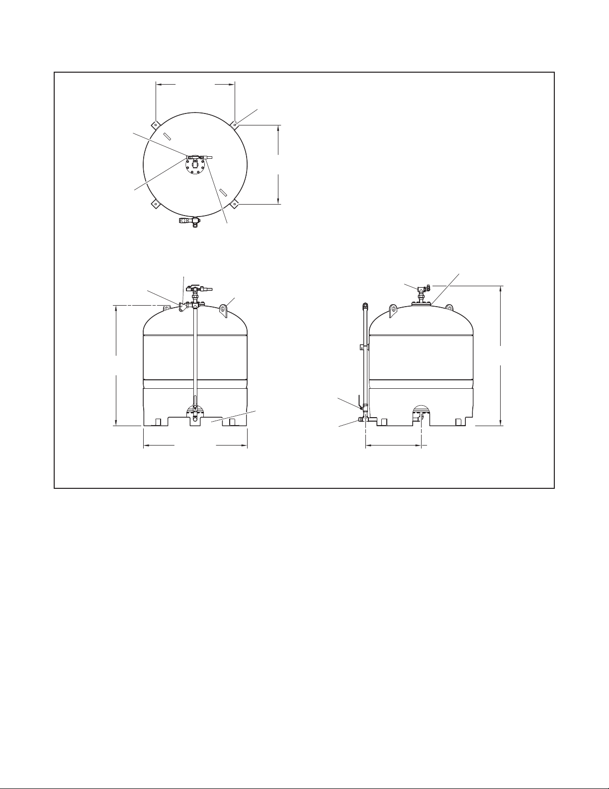
Water Supply Tank Assembly
The water supply tanks should be
installed so that they can be easily
refilled after use. Tanks must be
installed indoors or inside of a weather-
proof enclosure where operation tem-
perature limits are maintained. Secure
the tanks to the floor using four fasten-
ers through the mounting feet on the
water tank. Tanks should be spaced
at least 24 inches (0,61 m) apart to
allow for access during installation,
operation, and servicing procedures.
Ensure that the floor is strong enough
to support the weight of the water
tanks. The approximate weight of one
600 gallon (2271 liter) water tank filled is
7500 lbs. (3402 kg), approximate 2500
lbs. (1133 kg) when empty.
Nitrogen Discharge Piping
Each Nitrogen Discharge Connection
from the Nitrogen Supply Skid must be
piped to the inlet of a Water Tank Nitro-
gen Supply Connector using 1-1/2 inch
(3,81 cm) Schedule 40 Stainless 316
pipe. The connection must be made of
less than 19 feet (5,79 m) of pipe with
no more than three 90 degree elbows
and three unions.
Water Tank Discharge Piping
It is necessary to pipe the discharge of
the two water tanks together in a 1200
Gallon (4542 Liter) skid. The piping can
be completed using the same pipe as
the rest of the system. It is recom-
mended to complete the piping with
a Wye connecter to reduce the fric-
tion loss of the converging flows. (Ref.
Figure 1) Regardless of piping configu-
rations, hydraulic calculations must be
completed to include all of the pipe and
fittings from both tank assemblies.
Water Tank Nitrogen Drain Valve
Discharge Piping
The high velocity of nitrogen through
the Water Tank Nitrogen Drain Valves
when emptying a discharged system
can cause damaging levels of sound,
and the large volume of nitrogen can
deplete the oxygen concentration
inside a room where it is being dis-
pensed. It is recommended to pipe the
discharge from the Water Tank Nitro-
gen Drain Valves into an area where
high sound levels are acceptable and
where the nitrogen can be vented to
the outside.
Piping
Pipe, tube, and nipples are to have the
burrs and fins removed after cutting.
Apply pipe thread sealant to male
threads only. When using TEFLON tape
or paste sealant, do not apply the tape
or sealant any closer than one thread
from the inlet of any pipe connection.
Prior to installation, each pipe or tube
section is to be swabbed internally by
running a clean rag, sponge, or other
absorbent material, through the pipe
or tube as needed to meet the internal
cleanliness requirements of NFPA 750,
Standard on Water Mist Fire Protection
Systems.
Hangers
Selection and installation of the piping
system hangers on all piping added
to the TYCO AQUAMIST Red-E Mist
Supply Skid must be in accordance
with the specifications of NFPA 13,
Standard for the Installation of Sprin-
kler Systems, and NFPA 750, Standard
on Water Mist Fire Protection Systems.
Install FM Approved pipe hangers in
accordance with good piping practices
as well as the following standards:
•
Refer to ASME B31.1, “Power Piping
Code,” and any appropriate local
codes and standards
•
A hanger should be installed
between ttings when the ttings
are more than 2 ft. (0,6 m) apart.
Setting the
Skid for Service
Use the following procedure when
setting the system for service the first
time, or after service which involves
complete draining of the system:
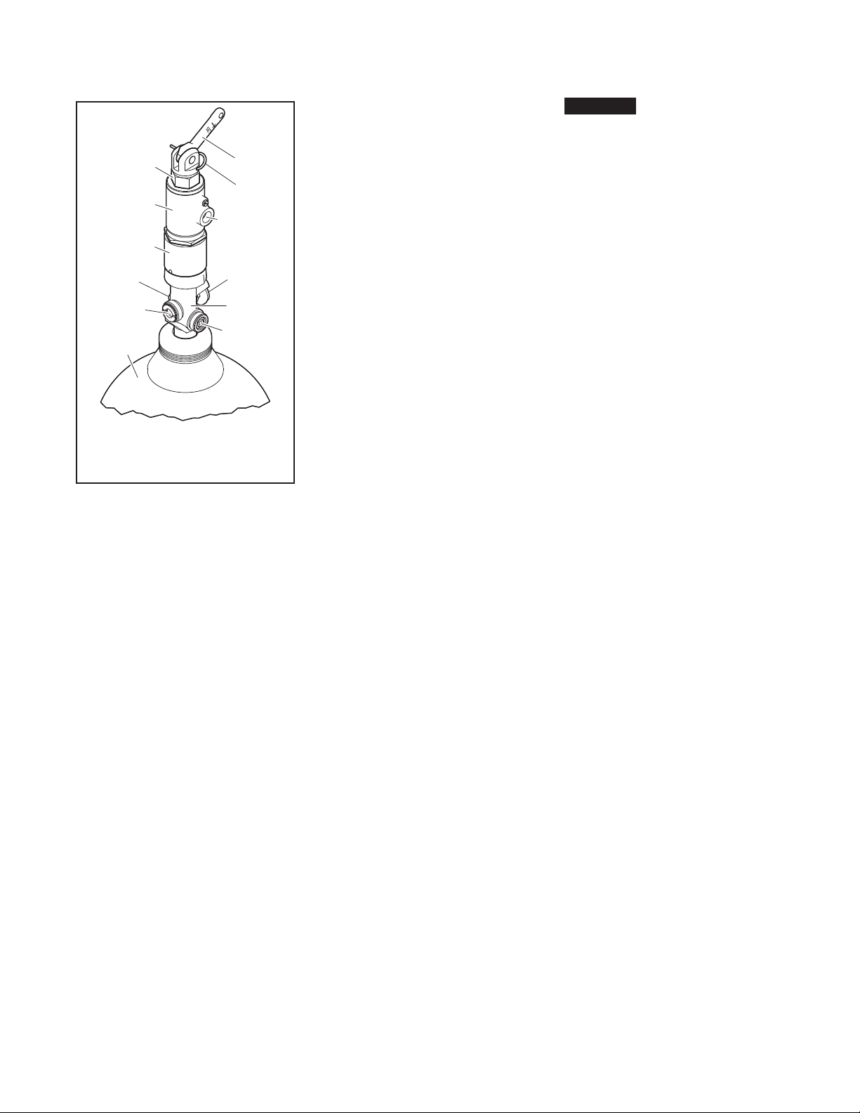
Step 1. Test HF Electric Actuator and
Booster Actuator.
When testing the HF Electric Actuator
and Booster Actuator they must not be
installed on the CV-98 cylinder valve. If
installed, testing the electronic detec-
tion system will cause actuation and
discharge of the system. In order to
properly test the electric detection and
actuation, attach the Booster Actuator
to the HF Electric Actuator and ener-
gize the release circuit.
When the HF Electric Actuator/Booster
Actuator is actuated correctly, the
piston in the bottom of the actua-
tors will be locked in the down posi-
tion. Reset the HF Electric Actuator
and Booster Actuator by following the
instructions in the Skid Reset after Dis-
charge section.
Step 2. Install HF Electric Actuator and
Booster Actuator.
The Actuator Stack can be installed on
any of the four or eight nitrogen cylin-
ders on the Nitrogen Supply Skid (Ref.
Figure 7). To install the actuator stack,
make sure that the Booster Actuator
is set to the armed position. This can
be confirmed by visually checking the
position of the top and bottom pins.
When in the set position, the top pin
will be approximately flush with the
top of the actuator. The bottom pin will
be flush with the inside surface of the
actuator.
If the Booster Actuator requires setting,
use the Arming Tool and follow the
instructions listed in the Skid Reset
after Discharge section. Then, hand-
tighten the actuator onto the cylinder
valve. Next, make certain that the HF
Electric Actuator is in the armed posi-
tion. When in the set position, the top
pin will be flush with the actuator.
If the Electric Actuator requires reset-
ting, use the Arming Tool and follow the
instructions listed in the System Reset
after Discharge section. Then hand-