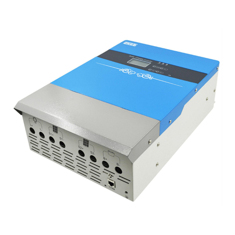
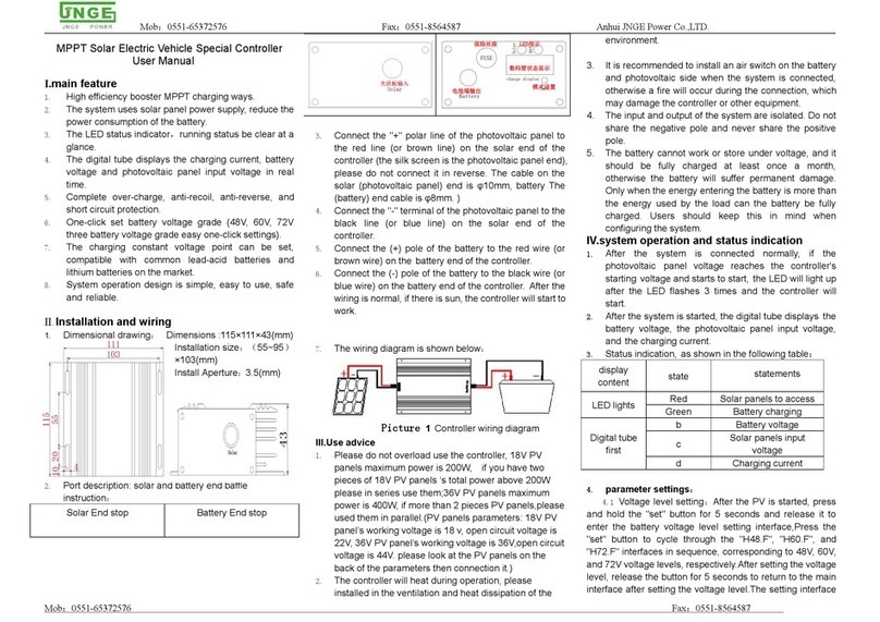
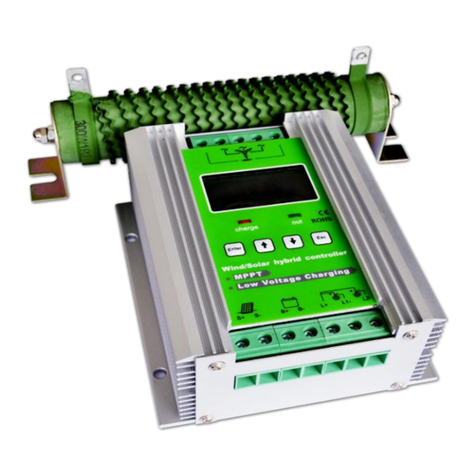
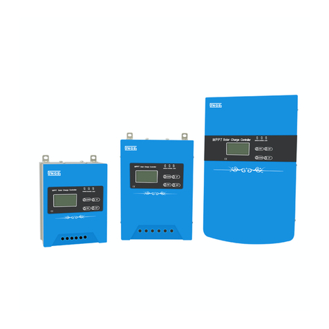
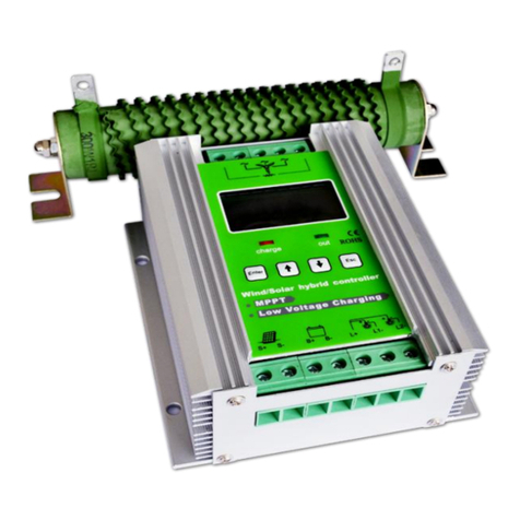
JNGE Power JN-K Series User manual

Anhui JNGE Power Co., LTD
JN-K、JN-R Series PWM Solar Charge
Controller
Product manual
Anhui JNGE Power Co.,LTD
ADD:No.99 Yonghe Rd,High-Tech Zone,Hefei,Anhui Phone:0551-65372576

PWM Mode Solar Charge Controller Manual
ADD:No.99 Yonghe Rd,High-Tech Zone,Hefei,Anhui Phone:0551-65372576 http://www.hfjnge.com
- 1 -
Catalog
1.Safety instructions..................................................................................................................................... - 2 -
1.1 Security identity............................................................................................................................- 2 -
1.2 Safety instructions....................................................................................................................... - 2 -
2.Product features.........................................................................................................................................- 3 -
2.1 Overview..................................................................................................................................... - 3 -
2.2 Product features.........................................................................................................................- 4 -
2.3 Product appearance.................................................................................................................... - 4 -
3.Installation instructions............................................................................................................................. - 5 -
3.1 Installation precautions.............................................................................................................. - 5 -
3.2 Installation instructions................................................................................................................- 6 -
3.3 Wiring.............................................................................................................................................- 7 -
3.4 Photovoltaic array requirements...............................................................................................- 8 -
3.5 Cable type selection requirements...........................................................................................- 8 -
4. Instructions for operation.........................................................................................................................- 9 -
4.1 LCD display...................................................................................................................................- 9 -
4.2 Key............................................................................................................................................... - 10 -
4.3 Setting operation....................................................................................................................... - 11 -
5.Equipment parameters........................................................................................................................... - 12 -
5.1 Protection function................................................................................................................... - 12 -
5.2 Troubleshooting......................................................................................................................... - 13 -
5.3 System maintenance................................................................................................................- 14 -
6.Warranty commitment.............................................................................................................................- 14 -
7.Equipment parameters........................................................................................................................... - 15 -
8.Installation dimension............................................................................................................................. - 17 -
9. Packing list and communication module accessories...................................................................... - 18 -

PWM Mode Solar Charge Controller Manual
ADD:No.99 Yonghe Rd,High-Tech Zone,Hefei,Anhui Phone:0551-65372576 http://www.hfjnge.com
- 2 -
1.Safety instructions
1.1 Security identity
The following safety symbols may appear in this manual with the following meanings
Safety symbols
meaning
dangerous
ignoring safety warnings,it can lead to serious accidents that could result in
personal injury.
warning
Indicates that if safety warnings are ignored, there is a risk of serious injury
accident, serious damage to equipment or interruption of major business
attention
Indicates the risk of moderate injury accident, moderate equipment damage or
partial business interruption if safety warnings are ignored.
instructions
Indicates that the content is additional information to the body.
For electrical and electronic equipment, safety involves the whole process of installation,
commissioning, operation and maintenance。So,Improper use or improper operation will endanger the
life and personal safety of operators or third parties as well as the safety of equipment。In order to avoid
casualties and equipment damage, the operation and maintenance process must strictly comply with the
following dangerous, warning and attention to the safety information tips.
1.2 Safety instructions
Warning!
All installation of the controller must be performed by a professional technician。The professional
technical personnel must go through the special training, read the manual completely and master the
operation related safety matters.
The company shall not be liable for any injury caused by non-professional installation operation.
Failure to install and operate the controller according to the instructions in this manual will not be
covered by our warranty.
①Before installation
Attention !
When receiving the product, please check whether controller is damaged in the process of
transportation. If there is any problem, please contact the company or the transportation company
immediately.
②During installation
Before installing the controller, make sure that the controller is not electrically connected or
energized.
Warning!
The controller damage caused by the following circumstances or other losses will not be covered by
our warranty.
When the photovoltaic array is configured, ensure that the maximum short-circuit current of the dc
side is within the allowable range of the controller, otherwise the controller may be damaged
irrecoverable.
When the photovoltaic array is configured, it is important to ensure that the open circuit voltage of
each photovoltaic cluster string does not exceed the maximum input range of the controller, otherwise it
will cause non-recoverable damage to the controller.。

PWM Mode Solar Charge Controller Manual
ADD:No.99 Yonghe Rd,High-Tech Zone,Hefei,Anhui Phone:0551-65372576 http://www.hfjnge.com
- 3 -
③During operation
④Maintenance
2.Product features
2.1 Overview
First of all, thank you for buying and using our JN-K and JN-R PWM mode solar
controllers, in order to better understand and use our products.Please read the manual
carefully before installing and using this product and keep it properly.The installation and
debugging of the product shall be conducted in accordance with this manual.Improper
installation and operation may cause personal injury, equipment damage and property
damage.
This series of controller adopts the most advanced CNC technology design, LCD display,
automatic operation。Using pulse width modulation (PWM) type battery charging mode and
unique control technology will greatly improve the battery life.
The charging current of the selected controller should not be greater than 0.3 times the battery
capacity. If it is greater than 0.3 times the battery capacity, the battery will be damaged or the battery life
will be reduced.
Improper installation environment of controller will affect machine performance and may cause
machine damage.
Do not install the controller in flammable or explosive places or storage places for flammable or
explosive materials.
Do not install the controller where there is explosive danger.
Do not install the controller where lightning may strike.
Do not install the controller where there is a lot of salt spray.
When controller is running, it is necessary to ensure the normal air convection around it.
The controller shall be installed in an upright position and shall ensure that the air duct is free from
obstruction.
Warning!
Before all devices are fully connected, be sure to disconnect the photovoltaic array end, battery
end, load end and other open (circuit breaker) or fuse.
Prevent water from entering controller.
Attention!
All electrical installations must comply with local and national electrical installation standards.
To ensure safe operation, proper grounding, proper conductor size and necessary short circuit
protection are required.
The connection cable must choose suitable specification, the connection is firm and the insulation is
good.
Check all wiring connections are tight after installation to avoid the risk of heat accumulation due to
virtual connections.
Dangerous!
Do not open the machine cover when the controller is live!
Dangerous!
Maintenance work shall be carried out by professional maintenance technicians.
The controller needs power off before maintenance. After power off, it can be removed after 5
minutes.

PWM Mode Solar Charge Controller Manual
ADD:No.99 Yonghe Rd,High-Tech Zone,Hefei,Anhui Phone:0551-65372576 http://www.hfjnge.com
- 4 -
2.2 Product features
This controller is applicable to solar off-grid system and can automatically control the
charging and discharging process。Its comprehensive self-test function and electronic
protection function can avoid controller damage caused by installation error and system
failure.
◆Using CPU processor with high speed and superior performance, the high precision A/D
sampling ensures the accuracy of sampling;
◆Intelligent temperature control descending current charging
◆12V/24V battery system voltage automatic identification, 48V separate battery system
◆Efficient PWM charging method prolongs the battery life and improves the system
performance
◆Adopt imported power MOSFET as electronic switch, low loss, high reliability
◆LCD and button interface are adopted to facilitate the display and operation
◆With temperature compensation control algorithm, the system automatically adjusts
charging and discharging parameters to improve the service life of battery
◆Using RS485 communication bus, communication speed is fast, communication
protocol compatibility is good, realize PC background direct connection monitoring
◆The controller can connect to upper computer through RS485 and support expansion of
WIFI module and GPRS module to realize APP cloud monitoring (optional)
◆The controller has automatic protection functions of over temperature, over discharge,
over charge and short circuit
◆Photovoltaic array and battery reverse connection automatic protection function
◆5V dc output, can be used to power mobile phones or digital products
2.3 Product appearance
Figure 2-1 JN-K, JN-R Product Appearance Dimensions

PWM Mode Solar Charge Controller Manual
ADD:No.99 Yonghe Rd,High-Tech Zone,Hefei,Anhui Phone:0551-65372576 http://www.hfjnge.com
- 5 -
2-1:Product dimension
Name
Weight/Dimension
Note
Model
JN-K
JN-R
Weight(kg)
0.41
1.4
As reference only
Dimensions L*D*H(mm)
166*98*47
207*134*70
3.2 Interface definition
Figure 2-2 Product Interface Definition Diagram
2-2 Product interface definition
NO.
Name
Function
Explain
1
PV+
PV array positive pole
PV array input terminal
2
PV-
PV array negative pole
3
BAT+
Battery positive pole
Battery terminal
4
BAT-
Battery negative pole
5
LOAD+
DC load positive pole
Battery load output terminal
6
LOAD-
DC load negative pole
7
Temp sensor
External temperature test
terminal
Measure external battery temperature
8
RS485
Communication port
Realize upper computer, WIFI, GPRS
communication monitoring
9
USB
DC5V output
5V-USB output 0.5A
3.Installation instructions
3.1 Installation precautions
(1) Read the entire installation section and familiarize yourself with the installation steps before
installing
(2) Be very careful when installing battery, for installation of open lead-acid battery should wear a
protective lens once in contact with the battery acid, please rinse in time with clean water.

PWM Mode Solar Charge Controller Manual
ADD:No.99 Yonghe Rd,High-Tech Zone,Hefei,Anhui Phone:0551-65372576 http://www.hfjnge.com
- 6 -
(3) Avoid placing metal objects near the battery to prevent short circuit of the battery.
(4) Battery charging may produce acid gas, ensure good ventilation around the environment
(5) Please install indoors and outdoors to avoid direct sunlight and rain infiltration.
(6) The connection point of virtual connection and the corroded wire may cause great heat to melt the
insulation layer of the wire, ignite the surrounding materials, and even cause fire. Therefore, it is
necessary to ensure that the connecting head is tightened, and the wire is better fixed with the tie
belt, so as to avoid the loose connecting head caused by the shaking of the wire during mobile
application.
(7) The installed battery should match the charging voltage of the controller and the recommended
charging current range.
Danger!
Explosion danger!Never install controller and battery in the same confined space!Do not install in
a confined space where battery gas may accumulate
3.2 Installation instructions
Step 1:Select installation site
Avoid installing controller in direct sunlight, high temperature and water easily, and ensure good
ventilation around the controller.
Step 2:Unpacking and inspection
(1) Check outer packing for breakage or distortion;
(2) Open box inspection: one controller, one manual, one attachment, etc;
(3) Check whether appearance and accessories of the main machine are in good condition;
Please contact us for any of the above exceptions.
Step 3:Fixed controller
Fix controller to the installation platform or installation bracket of the space plane through mounting holes
on both sides of controller with screws, and reserve enough natural convection heat dissipation space
around installation
Figure 3-1 Reserved schematic diagram around installation

PWM Mode Solar Charge Controller Manual
ADD:No.99 Yonghe Rd,High-Tech Zone,Hefei,Anhui Phone:0551-65372576 http://www.hfjnge.com
- 7 -
3.3 Wiring
Attention:For installation safety, we recommend a wiring sequence;
Attention:Controller is designed with common positive poles;
Warning:Do not connect load end to electrical equipment that exceeds surge power of controller
to prevent damage to controller!
Warning:When moving, make sure all connections are secured. Virtual connections can lead to
heat accumulation and fire in severe cases;
Step 1:Connect battery, photovoltaic module, load, temperature sensor, monitoring background;
Connect the battery, load, photovoltaic module, temperature sensor, monitoring background (upper
computer, WIFI module or GPRS module) in turn, disconnect all switches in the wiring process, pay
attention to distinguish between positive and negative terminal cable access;
Before connecting battery, make sure battery is in a normal state to ensure the normal operation of
system.
Step 2: wiring
Lock cable to the terminal through hole on the lower side of housing,
Figure 3-2 Controller connections
Warning:Do not connect photovoltaic panel to battery end of controller, or it will burn out
controller.
Battery positive and negative terminal and the wire connected to the positive and negative terminal (such
as the exposed metal part of the cable terminal) if short circuit will cause fire or explosion risk, please be
careful to operate.

PWM Mode Solar Charge Controller Manual
ADD:No.99 Yonghe Rd,High-Tech Zone,Hefei,Anhui Phone:0551-65372576 http://www.hfjnge.com
- 8 -
Explain:monitoring background supports PC upper computer, supports WIFI module and GPRS
module to expand and realize APP cloud monitoring (optional). For details, please refer to operating
manual of PC upper computer and APP;
Step 3: checking connection
Check whether polarity of all wiring is correct and whether terminals are locked;
Step 4: Boot sequence
Recommended turn on, turn off sequence:close battery switch, photovoltaic switch or load switch in
turn;shut down photovoltaic and load switch, and then turn off battery switch.
3.4 Photovoltaic array requirements
Parameter
Model
JN-K
JN-R
System rated voltage
12V
24V
48V
12V
24V
48V
PV Max VOC
22V
44V
88V
22V
44V
88V
3.5 Cable type selection requirements
The following table is conversion of copper wire diameter size according to current level. The actual
diameter size of wire cable metal should be greater than or equal to the data in the table
Parameter
Model
JN-K
JN-R
Current/A
10
20
30
30
40
50
60
Wire dia/mm2
2
4
6
6
8
10
12
AWG
14
11
9
9
8
7
6
Warning!
1.Electric shock risk!Do not touch live parts of high voltage pv module with bare hands;
2.Please ensure that solar array voltage in the system does not exceed the maximum input voltage
range of controller;
3.The system needs to connect inverter, please connect inverter directly to battery, do not connect to
load end of controller;

PWM Mode Solar Charge Controller Manual
ADD:No.99 Yonghe Rd,High-Tech Zone,Hefei,Anhui Phone:0551-65372576 http://www.hfjnge.com
- 9 -
4. Instructions for operation
4.1 LCD display
The display of controller adopts segment code screen, and layout of display screen is shown below:
Figure 4-1 Display layout
4-1 Introduction to icon functions
4-2 Field function introduction
Name
Define
Functional specifications
V battery
Battery
voltage
field lights up to display current battery voltage in data display area
V PV
PV voltage
field lights up to display current pv panel voltage in data display area
I charge
Charging
current
field lights up to display current battery charging current in data display
area
I load
Discharging
current
field lights up to display current battery discharge current in data display
area
Under
under
voltage
field to set battery overdischarge voltage, when battery undervoltage, field
flashing
Under-R
Under
recover
voltage
field lights up to set battery overdischarge return voltage
OVD
Over
charging
voltage
field lights up, battery overcharge pressure can be set, when battery
overcharge field flashing
OVD-R
Over
charging
recover
field lights up, can set battery overcharge return voltage
Float
Float voltage
field lights up to set floating charging pressure of the battery, and in floating
Name
Define
Functional specifications
day
icon lights up to indicate daytime
night
icon lights up to indicate night
PV
icon is highlighted to check access to pv array
battery
icon is highlighted to indicate battery access, inside indicates
battery power
load
load lights up to indicate that the load has output
state
icon lights up and scrolls to indicate charging state and discharging
state respectively
error
icon flashes to indicate that system is in trouble

PWM Mode Solar Charge Controller Manual
ADD:No.99 Yonghe Rd,High-Tech Zone,Hefei,Anhui Phone:0551-65372576 http://www.hfjnge.com
- 10 -
charging stage, field flashes
BCV
Boost
charging
voltage
When field lights up, battery charging voltage can be set to rise, and in
stage of rising charging, field flashes
Time
Time 1 set
When field lights up, you can set first time period of time control (first light
of the light control). When setting 24, controller is in user mode.The default
value is 24.
Time1
Time 2 set
field lights up. In street lamp mode, second time period of time control can
be set (light control time of lights on and off).。
Time2
Time 3 set
field lights up, in street lamp mode, can be set time control third period
(light control the second light。
L-CON-V
Light-control
voltage set
field lights up, first display area shows 1, can set light on (light on)
voltage;After light control on setting is completed, first display 2 can set
light control off (light control off) voltage。
ERROR
Alarm
indication
field lights up when there is a failure
4.2 Key
4-3 Key function
Key
Function
Model
SET,function 一:main menu,function 二:parameter set save
key;
JN-K/JN-R
UP,function 一:turn page on display parameters,function 二:
parameter setting plus;
JN-K/JN-R
DOWN,function 一:turn page on display parameters,function
二:parameter setting minus;
JN-R
Set exit ESC key;
JN-R
UP and DOWM(JN-K does not have a "DOWN" button)function switch:
Figure 4-2 UP, DOWM switching interface

PWM Mode Solar Charge Controller Manual
ADD:No.99 Yonghe Rd,High-Tech Zone,Hefei,Anhui Phone:0551-65372576 http://www.hfjnge.com
- 11 -
4.3 Setting operation
4.4.1、General parameter setting:
Press SET button in standby mode to enter undervoltage setting interface,continue to press
SET key to enter other Settings interface,press ESC button in any interface to exit setting interface
(JN-K no ESC,stop in Settings interface for 5 seconds to exit the Settings interface),back to
standby screen, other general parameter Settings are similar to undervoltage Settings;
Figure 4-3 General parameter setting -- flowchart of battery undervoltage point setting
4.4.2、Light control parameter setting
Figure 4-4 Light-control parameter set
4.4.3、Time control parameter setting
Figure 4-5 Time control parameter setting diagram

PWM Mode Solar Charge Controller Manual
ADD:No.99 Yonghe Rd,High-Tech Zone,Hefei,Anhui Phone:0551-65372576 http://www.hfjnge.com
- 12 -
4.4.4 、Device connection to PC upper computer or APP (WIFI or GPRS mode), please refer to
corresponding upper computer user manual and APP user manual respectively;
explain
PC upper computer or APP (WIFI or GPRS mode) are optional accessories,
equipment single communication can only take one way, can not use several
communication modes at the same time!
5.Equipment parameters
5.1 Protection function
5-1 Protection function reference table:
Protection
function
Explain
Photovoltaic array
short circuit
Short circuit at input end of photovoltaic array, controller does not charge. The
display shows that photovoltaic input voltage is 0V. When short circuit is cleared,
charging will continue automatically
PV module
polarity reversal
When polarity of pv module is reversed, controller will not charge. display screen
shows pv input voltage is 0V, controller will not be damaged. After correcting wiring
error,controller will return to normal operation.
PV Under voltage
protection
When charging voltage of photovoltaic array is lower than rated input voltage range
of controller, PV undervoltage alarm can be checked through upper computer or
APP, charging of battery group can be stopped.
PV Over voltage
protection
When charging voltage of photovoltaic array exceeds rated input voltage range of
controller,red alarm light flashes, PV over-voltage alarm can be detected through
upper computer or APP, controller stops charging battery.
Reverse polarity
of battery
When battery polarity is reversed, controller will not work and will not be damaged.
After correcting wiring error, switch will continue to work normally
Battery
undervoltage
protection
When battery voltage is lower than set undervoltage value, it will automatically stop
load output to prevent the battery from excessive discharge and damage.
Battery overload
protection
When battery voltage is lower than set undervoltage value, display screen displays
Under and ERROR alarm and automatically stops load output to prevent battery
from being damaged due to excessive discharge.
Battery
overvoltage
protection
When battery voltage reaches overvoltage protection set value, it will automatically
stop charging battery to prevent battery from overcharging and damage.
Night protection
Because battery voltage is larger than photovoltaic module voltage at night,
automatic protection prevents battery voltage from discharging through photovoltaic
module;
Equipment
overheating
protection
Controller is equipped with a temperature sensor inside. When temperature is
higher than set value, charging work will be stopped.
High voltage
surge
This controller can only protect high voltage surge with small energy. It is
recommended to install external lightning arrester in area with frequent lightning.

PWM Mode Solar Charge Controller Manual
ADD:No.99 Yonghe Rd,High-Tech Zone,Hefei,Anhui Phone:0551-65372576 http://www.hfjnge.com
- 13 -
5.2 Troubleshooting
If following failure occurs, please follow method below to check and troubleshoot:
5-2 Troubleshooting table
Error
Alarm icon
Possible reasons
Methods
Array
overvoltage
V PV and
showi
ng & flashing
number of pv array series
is more or some pv
modules are abnormal
Disconnect pv array, reduce number of pv array
groups in series or detect voltage value of each pv
module to ensure that open circuit voltage of pv
array does not exceed value set in the "pv electrical
parameters" table;
Battery
overvoltage
OVD and
showi
ng & flashing
1.overvoltage protection
point of controller is lower
than highest value of
charging range;
2. Aging or over
discharge of battery;
3. Overdischarge of
battery;
4.Large dynamic change
of load;
1.Reset battery overvoltage protection point through
device button or PC upper computer or APP;
2.The aging battery needs to replace battery;
3.Overdischarge requires manual setting of battery
voltage level;
4.Reduce large dynamic changes of load;
Battery
undervoltage
Under and
showi
ng & flashing
battery voltage is lower
than undervoltage
protection set
1. Reduce or disconnect load. If alarm is lifted and
battery voltage returns to normal, it means load
power is too large or battery voltage and capacity
are too low, overload may easily lead to under-
voltage protection;2. Disconnected load controller
still gives an alarm, battery voltage has not
recovered to over-discharge recovery set value. It is
necessary to charge battery group through
photovoltaic or other ways to make battery group
voltage reach set value of recovery point before
fault can be relieved
Indicator light
is not on,
display
screen is not
displayed
battery voltage is lower
than device starting
voltage
Use multimeter to test whether voltage at both ends
of battery is lower than 7V;
It is necessary to charge battery pack by other ways
to make battery pack voltage reach more than 8V;
Radiator
overheating
showi
ng & flashing
1. ambient temperature is
too high, heat dissipation
of equipment is poor, and
air convection is not
smooth
1.Check installation environment of equipment,
remove sundries around equipment, and ensure
smooth natural ventilation;
Charging flow
I charge and
showi
ng & flashing
Overcurrent protection
check current detection
abnormal, false action
Restart several times if not solved, need to return to
factory for maintenance;
Loading flow
I load and
showi
ng & flashing
load power is too high
1. Reduce load power;
2. Restart and remove fault;
3. Without excessive perceptual and capacitive
load;
Note:In addition to failure of battery to start up due to low voltage, other failures can refer to the failure
information through background of PC or mobile APP

PWM Mode Solar Charge Controller Manual
ADD:No.99 Yonghe Rd,High-Tech Zone,Hefei,Anhui Phone:0551-65372576 http://www.hfjnge.com
- 14 -
5.3 System maintenance
In order to maintain optimal long-term performance, it is recommended that following inspections be
performed twice a year.
• Verify that controller is securely installed in a clean, dry environment.
• Make sure airflow around controller is not blocked and remove any dirt or debris from radiator.
• Inspect all exposed wires for insulation damage due to sun exposure, friction with surrounding
objects, dry rot, insect or rodent damage.If necessary, repair or replace conductor.
• Tighten screws on all electrical connection terminals as recommended.
• Check grounding of all components of system to verify that all grounding wires are firmly and
correctly grounded.
• Check all terminals for signs of corrosion, insulation damage, high temperature or burning,
discoloration, and tighten terminal screws to recommended torque.
• Check for dirt, nesting insects and corrosion and clean as required.
• If arrester has failed, replace failed arrester in time to prevent lightning damage to controller or
even other equipment of user.
Attention:electric shock risk!
Make sure that all power supply of controller is disconnected when above operation is carried
out, and check or operate accordingly!
6.Warranty commitment
Controller is guaranteed free of charge for one year, starting from the date of sale.
• Maintenance procedures before requesting maintenance, check with the user's manual to determine
if there is a problem with the controller。If this cannot be resolved, return controller in question to us,
prepaid, and provide date and place information relevant to purchase。In order to enjoy quick repair
guarantee service, returned products must be marked with model number, serial number and detailed
reason for failure, as well as type and related parameters of components in system, battery and system
load;This information is important to quickly address your maintenance needs.
If controller is damaged due to improper use or failure to follow this manual, company shall not be
liable!Maintenance procedures refer to above procedure, only maintenance cost is charged.
Declaration:The company reserves right to change products without prior notice!
version number:V1.0

PWM Mode Solar Charge Controller Manual
ADD:No.99 Yonghe Rd,High-Tech Zone,Hefei,Anhui Phone:0551-65372576 http://www.hfjnge.com
- 15 -
7.Equipment parameters
1. Parameters list
7-1 Parameters table
Parameters
Model
JN-K
JN-R
Rated voltage
12V
24V
48V
12V
24V
48V
Max PV VOC
22V
44V
88V
22V
44V
88V
Min PV VOC
>Vbat+1V
>Vbat+1V
>Vbat+1V
>Vbat+1V
>Vbat+1V
>Vbat+1V
Rated charging current
10A、20A、30A
30A、40A、50A、60A
Charging drop
≤0.7V
Discharging drop
≤0.2V
Static loss
0.3W
Communications
RJ45 interface/RS485 communication
USB output
5V/0.5A
Operating environment parameters
Liquid crystal display
temperature range
-20℃~75℃
Ambient temperature
-20℃~50℃
Storage temperature
-30℃~70℃
Humidity(℃)
10% ~90%
Protection grade
IP30
Boost charge duration(min)
120
Working state
default is 24H user mode
Battery temperature compensation parameters
Temperature
compensation
Upper limit
0mV∕℃∕2V
Lower limit
-8mV∕℃∕2V
Default
-4mV ∕ ℃∕2V

PWM Mode Solar Charge Controller Manual
ADD:No.99 Yonghe Rd,High-Tech Zone,Hefei,Anhui Phone:0551-65372576 http://www.hfjnge.com
- 16 -
7-2 Battery parameters refer to table:
Lead Acid Battery
Rated voltage (v)
12V system(1
string)
24V system(2
string)
48V system(4 string)
12V default
Over voltage(v)
13~17V
26~34V
52~68V
15.5V
Overtvoltage recover (v)
13~17V
26~34V
52~68V
15V
Charging limit voltage(v)
9~15V
18~30V
36~60V
14.9V
Boost charging voltage(v)
9~15V
18~30V
36~60V
14.4V
Boost return voltage(v)
9~15V
18~30V
36~60V
13.9V
Floating voltage (v)
9~15V
18~30V
36~60V
13.8V
Over discharging voltage (v)
7~13V
14~26V
28~52V
10.8V
Over discharging return voltage(v)
9~15V
18~30V
36~60V
13.1V
Ternary lithium battery(single 3.7V)
Rated voltage v
12V system(default 3
string)
24V system(default 6
string)
48V system(default 12
string)
3 string default
Over voltage(v)
10.5~15V
21~30V
42~60V
13.05V
Overtvoltage recover (v)
10.5~15V
21~30V
42~60V
12.6V
Charging limit voltage(v)
10.5~15V
21~30V
42~60V
12.6V
Boost charging voltage(v)
10.5~15V
21~30V
42~60V
12.4V
Boost return voltage(v)
10.5~15V
21~30V
42~60V
12V
Floating voltage(v)
10.5~15V
21~30V
42~60V
12.4V
Over discharging voltage (v)
6~13.5V
12~27V
24~54V
9.6V
Over discharging return voltage(v)
6~13.5V
12~27V
24~54V
11.4V
Lithium iron phosphate battery(single 3.2V)
Rated voltage (v)
12V system(default 3
string)
24V system(default 6
string)
48V system(default 12
string)
3 string default
Over voltage(v)
9~12V
18~24V
36~48V
11.1V
Overtvoltage recover v
9~12V
18~24V
36~48V
10.5V
Charging limit voltage(v)
9~12V
18~24V
36~48V
11.1V
Boost charging voltage(v)
9~12V
18~24V
36~48V
10.6V
Boost return voltage(v)
9~12V
18~24V
36~48V
10.2V
Floating voltage (v)
9~12V
18~24V
36~48V
10.6V
Over discharging voltage (v)
6~12V
12~24V
24~48V
8.4V
Over discharging return voltage(v)
6~12V
12~24V
24~48V
9.9V

PWM Mode Solar Charge Controller Manual
ADD:No.99 Yonghe Rd,High-Tech Zone,Hefei,Anhui Phone:0551-65372576 http://www.hfjnge.com
- 17 -
8.Installation dimension
Figure 8-1 JN-K Installation structure diagram
Figure 8-2 JN-K Schematic diagram of appearance structure
Figure 8-3 JN-R Installation structure diagram
Figure 8-4 JN-R Schematic diagram of appearance structure

PWM Mode Solar Charge Controller Manual
ADD:No.99 Yonghe Rd,High-Tech Zone,Hefei,Anhui Phone:0551-65372576 http://www.hfjnge.com
- 18 -
9. Packing list and communication module accessories
Table 9-1 Accessories reference list
NO.
Name
QTY
Note
1
JN-K(R)solar controller
1
2
Product manual
1
3
External battery temperature probe
1
4
RJ45 To USB module
1
Communication
function of upper
computer (optional)
5
Cable
1
6
Upper computer installation CD
1
7
Host computer communication instructions
1
8
RJ45 To GPRS communication module
1
APP,GPRS
(optional)
9
0.2m Special network cable
1
10
APP User manual
1
11
RJ45 To WiFi communication module
1
APP,WiFi
(optional)
12
0.2m Special network cable
1
13
APP User manual
1
This manual suits for next models
1
Table of contents
Other JNGE Power Controllers manuals
Popular Controllers manuals by other brands

Huawei
Huawei APAA00001 user manual

ABB
ABB ACS880-37 Hardware manual

cashco
cashco CLEAN STEAM Installation, operation & maintenance manual

Ducasa
Ducasa Smart Command Installation and operating manual

elero
elero InDrive M30/1.6 RH Operating and assembly instructions

Extron electronics
Extron electronics Basic MediaLink Controllers MLC 52 IR user manual