TYPE 32
Installation, Operation & Maintenance Instructions
PAGE 3
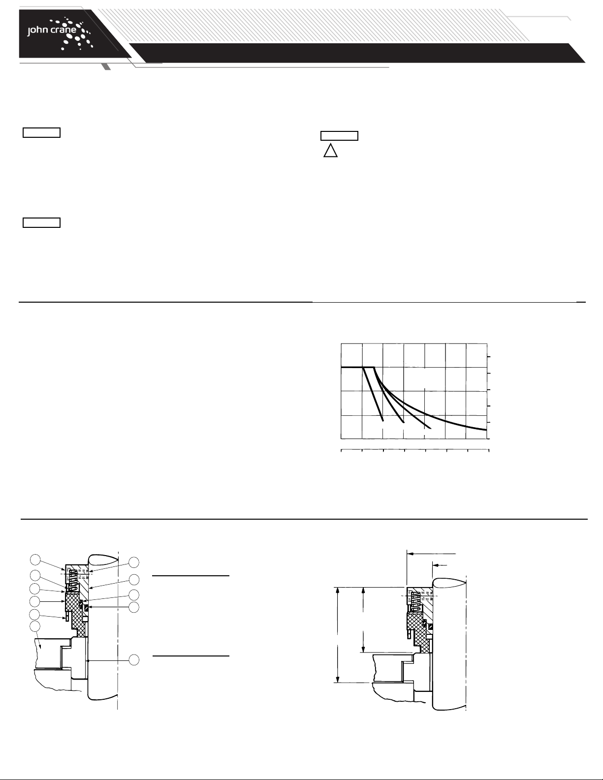
Setting the Seal
The seal must be installed to its correct working height within the tolerance allowed - refer to the installation dimen-
sion diagram. The procedure is the same for a shaft and a fitted sleeve.
If the working height is exceeded, the seal will be undercompressed and may leak: If the working
height is reduced, the seal will be overcompressed and this may cause high wear of the seal
faces.
1. Find the true seal position as follows:
a) Before the installation of the seat/mating ring. From the dimension tables find the dimension L39 for the size
of seal being fitted, and measure this distance from the seal housing/vessel face and mark the shaft; or,
b) After installation of the seat/mating ring. Using the standard working height dimension, measure this dis-
tance from the face of the seat/mating ring and mark the shaft.
The marked position is the point on the shaft where the back of the seal is to be located.
ATTENTION
Installing the Seal
Before starting the installation, read the following instructions carefully, both to be aware of special information, and because
the fitting sequence may be different depending on the construction of the vessel.
1. Remove the protective packaging from the seal; check for damage, and wipe clean.
2. Fit the seat/mating ring and the gland plate as described in the seat instruction manual. Incorporate the debris well at this
stage, if required.
NOTE: Use a suitable lubricant when fitting the seal. The recommended lubricants for an elastomer O-ring are soft hand soap
and water, glycerine, or silicone grease: do not use washing-up liquid, liquid soaps, or hand cleaning gels. Light min-
eral oil may be used with most elastomers.
Do not use hydrocarbon-based liquids on ethylene propylene elastomers.
3. Clean and sparingly lubricate the shaft.
4. Wipe the lapped surfaces of the seal and seat/mating ring perfectly clean.
Particular care should be taken when passing the seal over shaft shoulders to avoid impact and conse-
quent damage to the stepped bore of the seal face/primary ring.
5. Adjust the set screws until clear of the retainer bore. Slide the seal unit onto the shaft until the seal face rests on the
seat/mating ring; then compress the seal until the back of the retainer is in line with the seal setting mark, and, using the
Allen key provided, tighten the set screws sufficently to hold the seal in the setting position. Check that the seal is accu-
rately positioned, then continue to tighten the screws evenly and progressively to the torque recommended in the torque
table.
Accurate torque settings will avoid set screw damage and eliminate seal movement in operation.
ATTENTION
ATTENTION
ATTENTION
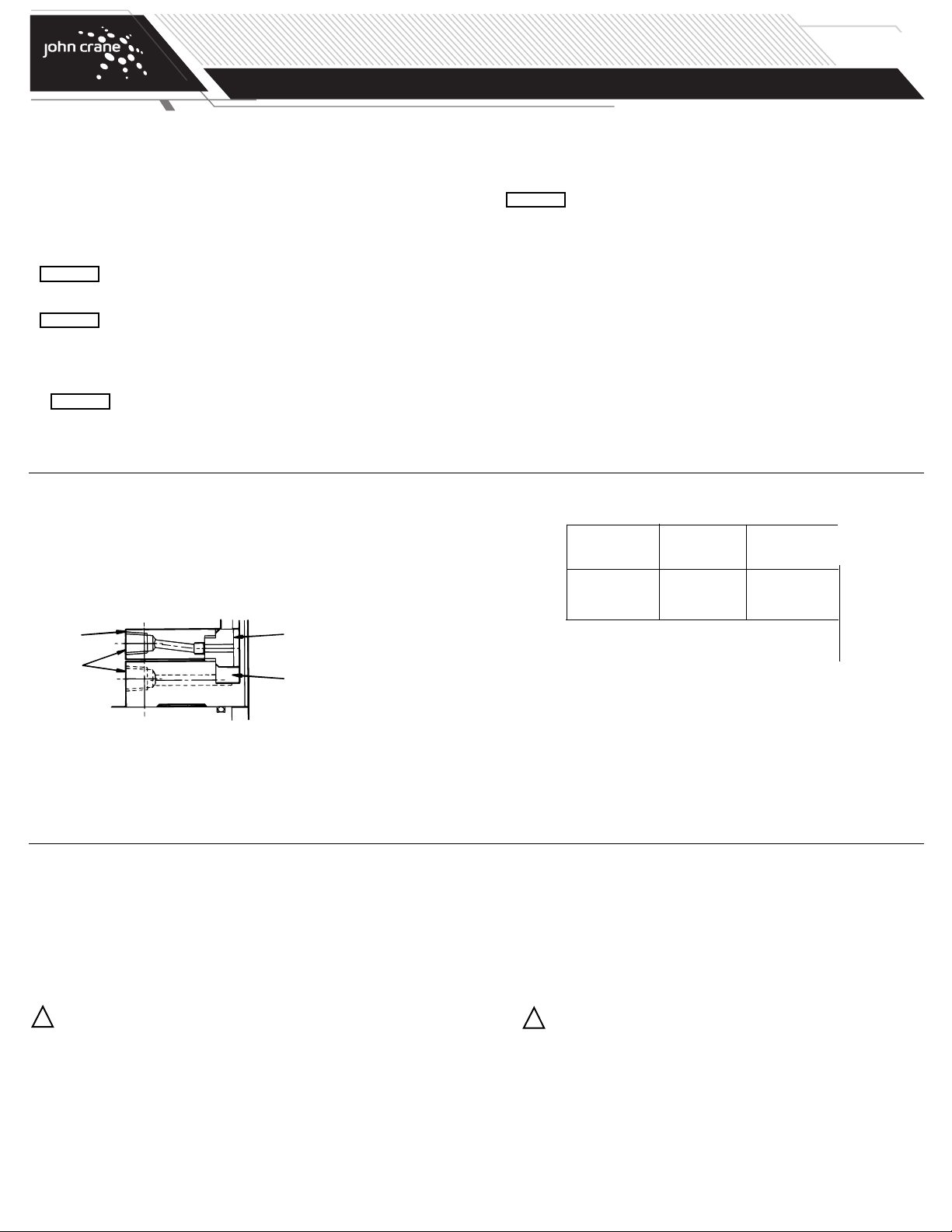
SEAT/
MATING
RING
DEBRIS
WELL
(OPTIONAL)
GLAND
PLATE
FLUSH/
PURGE
CONNECTIONS
Debris Well Option
Where the process liquid or gas must be protected from contamination by face wear particles, a debris well is available as
an option. In conjunction with the gland plate and seat/mating ring, the debris well forms a cavity to isolate and contain
face debris: tapped connections allow flushing of the cavity during the cleaning cycle.
The debris well is secured by the gland plate, and is therefore installed as part of the seat/mating ring installation
sequence - refer to the equipment and seat instruction manuals. Note that the inclusion of a debris well will affect seal
setting procedure 1a.
Before Commissioning the Equipment
1. Check the unit at the coupling for correct alignment of the motor or driver.
2. Complete the assembly of the equipment, and turn the shaft (by hand, if possible) to ensure free rotation.
The torque values given above are for stainless steel (001)
cup point set screws.
Set Torque
Seal Size Code Screw
Size Nm lbf ft
0250 to 0857 1/4 - 20 UNC 6 4.5
0889 to 1778 5/16 - 24 UNC 12 9.0
ecommended Torques for Set Screws
Maintenance
During operation, periodic inspection of the seal should be carried out. A measure of seal condition is the level of leakage,
and as no maintenance is possible while installed, the seal should be replaced when leakage becomes unacceptable. It is
recommended that a spare seal unit and seat/mating ring are held in stock to allow immediate replacement of a removed
seal.
Decommissioning the Equipment
1. Ensure that the vessel is electrically isolated.
If the equipment has been used on toxic or hazardous fluids, ensure that the equipment is correctly
decontaminated and made safe prior to commencing work. emember that fluid is often trapped during
draining and may be present inside the seal unit. The equipment instruction manual should be consulted
to check for any special precautions.
2. Ensure that the vessel is isolated by the appropriate valves. Check that the product is drained and pressure fully
released.
!
emoving the Seal
1. Referring to the vessel instruction manual, dismantle the equipment sufficiently to expose the seal.
2. Remove the seal, and then, if necessary, complete the removal of the gland plate and seat/mating ring in the
reverse order to installation.
NOTE: Although the original seal position may be marked on the shaft or sleeve as a reference point before seal
removal, the location must be checked even if the same seal and seat/mating ring specification is intended
as a replacement.
A seal unit should always be serviced after removal from duty. It is recommended that used seals are returned to a
ohn Crane service location, since rebuilding to as-new specification must be carried out by qualified personnel.
It is the responsibility of the equipment user to ensure that any parts being sent to a third party
have appropriate safe-handling instructions externally attached to the package.
!