John Crane API PLAN 74 User manual

Installation, Operation & Maintenance Instructions
1
API PLAN 74
SEAL SYSTEMS
1. General
1.1 Introduction
Plan 74 may only be installed, commissioned and maintained by an
authorized plant machinery specialist, paying close attention to these
instructions and all other relevant regulations. Failure to do this relieves
the manufactures from any liability or warranties.
This Instruction Manual is provided to familiarize the user with the
Plan 74 arrangement and its use. The instructions must be read and
applied whenever work is done on the Plan 74, and must be available to
operating and maintenance personnel.
These instructions will help to avoid danger and increase reliability. They
should be used with the appropriate mechanical seal Instruction Manual.
The following important terms and definitions are used in this document.
1.2 European and/or UK Declaration of Incorporation
(Machinery Directive 2006/42/EC, and UK SI 2008 No. 1597)
If appropriate this is attached.
1.3 European Declaration of Conformity
(Pressure Equipment Directive, 2014/68/EU)
This directive is not applicable to Plan 74.
1.4 European and/or UK Declaration of Conformity
(ATEX 2014/34/EU, and Equipment and UK SI 2016 No. 1107)
These instructions are intended for use with system operating in
Equipment Group II, category 2GD.
The Declaration covers the complete seal and system and the maximum
surface temperature is recorded in the Mechanical Seal Instruction Manual.
If appropriate this is attached.
2. Safety and Environment
The safety notes refer to the system supplied. They can never be exclusive,
and must be used in connection with the relevant safety regulations for the
machine, auxiliary equipment, plant and sealed product.
2.1 Warning symbols
The following symbols are used in this instruction manual to highlight
information of particular importance:
Danger
Mandatory instructions designed to prevent personal
injury or extensive damage.
Warning of electric current
ATTENTION Special instructions or information to avoid damage to
the system or its surroundings.
NOTE Information for easy installation and efficient operation.
Environmental note
Compliance is required with any additional warning signs affixed to the system.
2.2 Safety instructions
ATTENTION
Every working practice that compromises personal safety is to be
avoided. All safety requirements in this document must be strictly
adhered to.
In the event of an operating problem, the machinery must be switched off
immediately and made safe! Problems must be solved promptly.
Ensure suitable protective clothing is used when maintaining the system.
Plan 74 systems are commonly used with dual mechanical seal
configurations to reduce the hazard potential from flammable, explosive,
toxic or lethal process fluids. The intermediate, protective barrier gas, in
certain failure modes, may risk being contaminated by the process fluid.
During any maintenance operation operators must thus assume they will
be exposed to the liquid or gaseous properties of the process fluid and
have suitable protective gloves, clothing, respirators and equipment.
Particular note must be taken of the relevant guidelines for the electrical
installations.
A slight mechanical seal leakage will occur during normal seal operation.
Depending on the duty, this leakage can appear as a gas, a liquid or
a solid. In case of a worn or defective seal the leakage will increase.
The leakage may be hazardous or toxic, and a safe collection system is
required.
Surface temperatures above 60°C/140°F should be protected against
accidental contact.
The equipment sealed by this seal system must be operated within its
recommended design limits.
Compounds containing PTFE, fluorocarbons and perfluoroelastomers
should never be burnt as the fumes and residues are highly toxic. If this
accidentally occurs protective equipment should be worn as hydrofluoric
acid may be present.
Additional equipment/flanges/joint seals used within the system are to
be rated for the appropriate electrical and pressure requirements and are
to be chemically compatible with the barrier gas and process fluid.
• During venting or draining of the buffer region it should be piped to a
vent or reservoir where it can be safely contained or disposed.
• All above according to the local legislation.
• For further information and safe operating limits contact John Crane
• All periodical maintenance checks have to be in accordance with local
legislation and rules.
All welding or cutting operations are forbidden without permission from
John Crane.
If you are in any doubt please contact your local John Crane office for
further information before proceeding.
2.3 Environmental aspects
2.3.1 Company policy extract
“It is the policy of John Crane to manage its business activities in
an environmentally responsible manner, comply with all relevant
laws and regulations, prevent pollution, and continually improve its
environmental performance, certification to the latest issue of
ISO 14001 ensures compliance.”

Installation, Operation & Maintenance Instructions
2
API PLAN 74
SEAL SYSTEMS
John Crane adopts the ‘Design For the Environment’ (DFE)
principle in making this product. Using this product will benefit
the environment directly by:
• Reducing waste of precious resources through decreasing
the risk of leakage and minimizing energy consumption
• Preventing pollution through controlling harmful
emissions to the atmosphere and ground contamination
• Preserving valuable materials through the use of high
quality durable materials
2.3.2 Recycling
Product refurbishment
This product has been designed for long life.
Disposal
When the product is considered to be beyond economical repair and
potential reuse, it should be disposed of by environmentally beneficial
means. The product can be disassembled with ease.
Scrapped components
These should be handled with extra care due to possible contamination.
They should be recycled through local industrial recycling plants.
Packaging
All packaging materials used are made from recyclable,
environmentally friendly materials.
When in doubt or for further information and advice on this subject,
please consult John Crane.
3. Transportation and Storage
Transport and store the system where possible in its original packaging.
It is necessary to protect and preserve the integrity of the equipment
between shipment and installation/start-up at site. This is particularly
important when extended periods of storage are envisaged.
Plan 74 systems may be shipped first to the rotating equipment vendor
to be mounted on the rotating equipment baseplate complete with the
connecting pipework. In this event follow the instructions as given in the
rotating equipment IOM.
Plan 74 systems, which are to be mounted off the rotating equipment
baseplate, shall be shipped directly to site and shall be packed in
suitable crates or cases to protect them from damage during shipment.
All openings to the system are closed and sealed for shipping. In this
event follow the following instructions.
On arrival at site and before unloading for storage, a visual inspection
of the crate/case should be carried out for signs of damage during
shipment. In the event of any damage the crate/case must be opened,
and the contents thoroughly examined for signs of equipment damage.
If any seals are broken, then the system is assumed to be contaminated
and shall be cleaned accordingly.
If the parts are considered acceptable with no visual signs of damage,
the crate/case should be properly closed again prior to storage.
After checking for shipment damage, the following recommendations
should be undertaken to prevent deterioration arising from long term
storage.
• Plan 74 system should be replaced in their original packaging and if
possible the crate/case should be stored away from direct sunlight, in
a well-ventilated building with a hard floor.
• Temperature control is not normally necessary, but large temperature
fluctuations (>40°C/72°F) should be avoided.
• If stored outdoors, it is recommended that the crate/case be placed on
square timber bearers resting on a concrete or similar hard surface.
• The crate/case must then be wrapped with waterproof tarpaulin to
prevent ingress of water and dirt.
• Loose components or accessories in the case should be stored as
above, after proper itemization.
• A weekly visual external inspection of the protection and preservation
should be undertaken and any deficiencies noticed should be corrected
without delay.
• The system must be stored far from backwater to avoid the MIC
phenomenon (microbial corrosion).
NOTE Should water, condensation, sand, dirt or other contaminant
enter the system, through package/tarpaulin damage or
improperly positioned covers, the cause of the problem must
be eliminated and the equipment thoroughly dried and cleaned
before re-storing
If used system parts are to be transported to the manufacturer or a third
party they have to be cleaned, decontaminated and require safe handling
instructions externally attached.
ATTENTION The system normally does not require any preservatives;
it is resistant against most environmental conditions.
Ensure preservatives and cleaning agents do not affect
the elastomers.
4. Description of the System
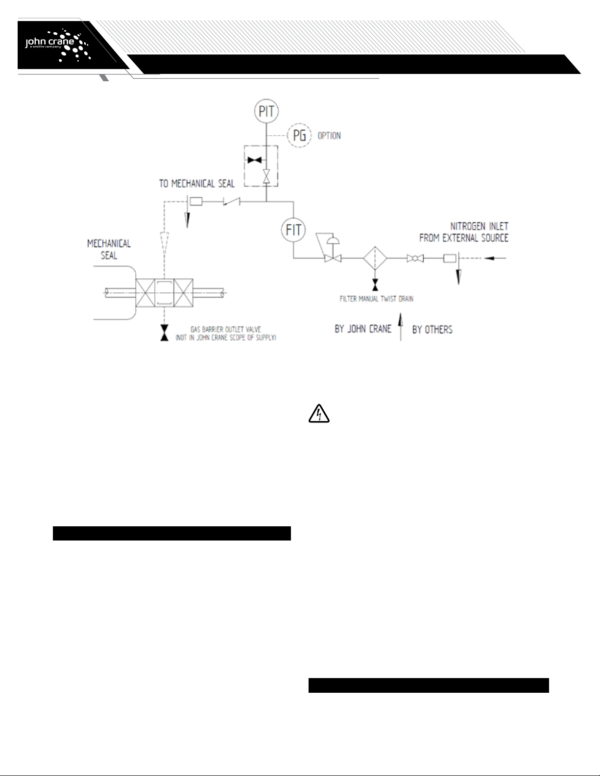
4.1 Function of the system
Where rotating machines (pumps, fans or mixers) work with hazardous
fluids, it is common practice to install double mechanical seals which
prevent leakage of the process fluid escaping into the surrounding
environment.
Non contacting dry running gas seals are frequently used for this
purpose.
The barrier fluid is a clean dry gas, normally Nitrogen, constantly
supplied to the mechanical seal inter-space from a reliable source at a
pressure greater than 2 bar (30 psi) above the product pressure.
The Plan 74 control panel includes a coalescing filter to ensure that the
final barrier gas supply to the seal is free of particulates and moisture.
Seal operating pressure is set by adjusting the control Plan 74 control
panel regulator in conjunction with the system pressure transmitter LCD
read-out (and/or pressure gauge if fitted).
Gas flows are visually monitored using the panel mounted flow
transmitter and pressure transmitter to provide a common signal
indicating either excess gas consumption and/or loss of gas supply
pressure.

Installation, Operation & Maintenance Instructions
3
API PLAN 74
SEAL SYSTEMS
4.2 Instrumentation and fittings
The system is usually supplied with the following:
• Barrier gas supply inlet (flanged or threaded)
• Panel outlet to seal (flanged or threaded)
• Pressure indicating transmitter (PIT)
• Flow indicating transmitter (FIT)
And, upon request with the following options:
• Pressure gauge (PG)
• Pressure switch (PS) instead of a PIT
• Flow indicator (FI) instead of FIT
• Flow switch (FS) with the flow indicator
5. Installation and Assembly
5.1 Before installation
Prior to installation ensure that internally all connecting pipe work
has been thoroughly cleaned. Remove protection caps from pipes and
connections. Check all fittings/connections for damage replacing if
necessary.
5.2 Control panel mounting
Refer to the appropriate arrangement drawing for mounting details.
It is recommended that piping between the Plan 74 control panel and
the mechanical seal should be kept below 2 metres (72 inches) in length
wherever possible. If this length is exceeded, consideration should be
given to increased frictional losses and, if necessary, allowances must be
made when setting the seal pressure.
It is advisable to install a vent connection in the interconnecting
pipe work close to the seal chamber.
With the gas supply isolated, connect the barrier gas supply piping to
the inlet connection on the Plan 74 control panel and connect the panel
outlet connection to the mechanical seal gas barrier in (GBI) connection.
Do not open gas supply at this time.
5.3 Electrical connections
Only authorized and qualified personnel are permitted to
carry out work on electrical systems. International and
local safety regulations must be followed in all cases.
Before connecting cables, check the electrical data on the name plate
matches the available power supply and complies with the area hazard
classification.
Refer to the diagrams in the terminal housing and the supplier's
instruction manual for wiring instructions. Connect the electrical
component using flexible conduit or armoured cable to assist removal of
the component for maintenance purposes.
If passive switching elements are installed in potentially explosive areas
you should add suitable protective devices, following the pertinent rules.
5.4 Leak check
During transit, tube fittings may work loose, check all fittings/
connections for tightness. First checking that the barrier gas supply
pressure is within the limits of the Plan 74 control panel, slowly open
the barrier gas supply line isolation valve allowing the control panel to
pressurize.
Using a suitable leak testing liquid check all joints and if necessary,
rectify any leaks found.
6. Commissioning and Decommissioning
6.1 Commissioning
Before starting the machine (pump or mixer) carry out the following
operations:

Installation, Operation & Maintenance Instructions
4
API PLAN 74
SEAL SYSTEMS
ATTENTION Before commencing the start-up procedure, review
and become familiar with all the available instructions
concerning the equipment, especially the safety
warnings.
a) Set the operating pressure to the ‘operating pressure’ on the
nameplate (typically 2 barg/30 psig greater than the process pressure)
by adjusting the regulator valve until the correct pressure is shown on
the pressure transmitter LCD (or pressure gauge if fitted). Turning the
regulator adjuster clockwise increases pressure and counter-clockwise
decreases pressure.
b) Purge the system of air by cracking open the vent connection (if fitted)
or by carefully cracking open the fitting at the seal and allowing barrier
gas to escape. After 10-15 seconds flow retighten the vent/fitting.
c) Recheck the operating pressure on the pressure gauge (if fitted) or
pressure transmitter LCD and fine tune if necessary.
d) Check that the pressure transmitter/switch and flow transmitter/
switch set points are correctly adjusted to suit the duty: Refer to the
table below.
TABLE 1. Alarm Signals
Alarm Name Instrument Set Point Notes
Low Pressure
/Shutdown
Required
Pressure Indicating
Transmitter (PIT) or
Pressure Switch (PS)
If barrier pressure drops
below the operating pressure
on the nameplate
REQUIRED
High Flow Alert
Flow Indicating
Transmitter (FIT) or
Flow Switch (FS)
If barrier flow rises
significantly above the value
indicated on the nameplate
RECOMMENDED
NOTE High flow alarms are recommended as indicators of significant
deviations from normal running conditions; some fluctuation
is expected during operation. The alarm value on the
nameplate is normally several times larger than the normal
running value, and is set based on the limits of barrier gas
that can safely be injected into the machine.
e) Start the machine
f) During initial start-up it is recommended that the gas pressure/flow is
regularly monitored for correct operation. Fine tune pressure setting if
necessary.
6.2 Normal running
The equipment shall be kept clean and free from debris to allow ease
of access and reading of the instrumentation. Care should be taken to
prevent damage to the system from accidental knocks and/or exposure
to excessive sources or heat. Disconnection of any part of the system
should not be undertaken without the appropriate authorization and until
all pressure has been completely discharged and system allowed to
cool. All joints broken for maintenance should be plugged off to prevent
ingress of dirt.
During normal operation the only attention required is to monitor the
barrier gas flow. Periodic visual checking (at least every 48 hours) of the
pressure/flow within the system is recommended.
If the consumption rate of the barrier gas is low, this can result in a
phenomenon where the check valve closes fully and does not open
again until the pressure difference across the valve exceeds its cracking
pressure. This results in sudden increases in flow when the valve opens,
and then zero flow once it closes again, which will appear as pulsations
in the flow indicator/indicating transmitter. This is normal and does not
indicate a failure mode for the equipment. If the pulsations are large
enough to trigger high flow alarms, these alarm values may need to be
raised to avoid nuisance alarms.
6.3 Decommissioning
Work on the seal or system must only be carried out
when the machine is stationary, depressurized, and
secured against any unforeseen start-up. Isolation from
connections to pressurization sources must be carried out.
Before carrying out any work on the seal or system, the equipment must
be shut down and the barrier region must be fully depressurized. Once
this has been done the barrier gas supply to the Plan 74 control panel
can be isolated.
Do not isolate the barrier gas supply before the pump is made
safe. Once the barrier gas supply is isolated carefully vent any residual
pressure from the panel and interconnecting pipe work and drain of any
liquids before carrying out any maintenance.
If the pump/panel is to be removed cover any open tubing fittings/
connections to prevent contamination.
NOTE It is recommended that a pressure test is carried out on
the system after any repair and before operation on the
equipment.
7. Maintenance
7.1 Routine maintenance
Check the following as part of regular site walk-around checks for
trouble-free operation:
• Check the condition of the coalescing filter element for contamination
(see Section 7.2).
• Barrier pressure. Compare with the operating pressure on the
nameplate.
• Barrier flow. Compare with the normal flow rate observed.
• Condition of alarm signals (see Section 7.3).
7.2 Filter
It is recommended that the element is checked after the first month
of operation and if no contamination is detected thereafter at 6-month
intervals.
Irrespective of visual condition it is recommended that the filter element
is replaced annually.
The filter bowl is pressurized and no attempt should be
made to remove it until the barrier gas supply has been
isolated and all residual pressure in the system safely
vented. Note that the machine must also be stopped and
depressurized before removing the barrier gas pressure.

Installation, Operation & Maintenance Instructions
5
API PLAN 74
SEAL SYSTEMS
7.3 Signals and alarms
A sudden or noticeably steady increase in the gas consumption should
be considered abnormal and may indicate a deteriorating seal. The
instrumentation on the system has the specific purpose of signalling
eventual malfunction of the mechanical seals. Possible alarm signals
indicating a malfunction are as shown in Table 2.
TABLE 2. Possible Alarm Signals Indicating a Malfunction
Effect Instrument Action Cause
Falling Pressure
Pressure Gauge (PG)
or Pressure Indicating
Transmitter (PIT)
A D to G
Low Pressure/
Shutdown Required
Pressure Indicating
Transmitter (PIT) or
Pressure Switch (PS)
B D to G
Falling Flow
Flow Indicating
Transmitter (FIT) or
Flow Indicator (FI)
C F or G
Rising Flow
Flow Indicating
Transmitter (FIT) or
Flow Indicator (FI)
A D or E
Pulsations
in the Flow
Flow Indicating
Transmitter (FIT) or
Flow Indicator (FI)
— H
High Flow Alert
Flow Indicating
Transmitter (FIT) or
Flow Switch (FS)
B D, E or H
Actions
A Investigate cause and monitor to ensure values do not breach
safe limits
B Shut down machine to prevent damage or loss of containment
C Check coalescing filter and gas supply
Causes
D Excessive leakage across the inboard seal or outboard seal
E Pipe work/joint failure
F Drop in the barrier gas supply pressure/flow
G Blockage of the coalescing filter
H Actuation of the check valve – see Section 6.2
The signal from the pressure transmitter can be used either:
• LOCALLY (with a Klaxon and/or beacon)
• REMOTELY (in the control room)
Consult the specific instrument manufacturers manual should there be a
malfunction.
If necessary for safety, the process the alarm signals could be used as a
trip function.
7.4 Instrument maintenance
All instruments require regular calibration, following local processes
and regulations. See the supplier's instruction manual for and additional
instructions for maintenance of electrical instruments.
7.5 Spare parts
Spare parts must conform to the established technical specifications of the
manufacturer. This is guaranteed with John Crane spare parts.
You are advised to stock the most important wear parts on site.
The following data is necessary for spare part orders:
• John Crane code/part number
• John Crane order/ref no.
• Part description
• Quantity
7.6 Annual maintenance checks
Disconnection shall be made by plant person in charge of authorization.
Before any maintenance operation the system, the machine must be
stopped and depressurized, then the barrier gas pressure must be fully
discharged, and the equipment allowed to cool to ambient temperature. A
suitable container should be available to contain any liquid drained from
the barrier system.
All parts requiring maintenance must be thoroughly decontaminated prior
to any work commencing.
All joints should be checked for tightness and signs of barrier gas leakage.
If present, all flange joints should be checked for tightness and, if
necessary, gaskets changed using replacements available from John Crane.
8. Accompanying Documents
Installation Drawing (job specific) or Typical Drawing and Operational
Data Sheet.
A name and data plate is fitted to each Plan 74 control panel. It contains
references and part numbers which must be quoted in any communication.
For replacement parts please contact your local John Crane
office, quoting the system code number.
9. Cold Environments
For environments with low ambient temperatures, winterization features
may be added to the Plan 74. These may include:
• The Plan 74 control panel may be supplied mounted in a heated
enclosure. The heating element requires electrical connection as part
of the installation and assembly procedure (see Section 6.2)
• Heat tracing and/or insulation may be required to maintain the
temperature of the barrier gas in the Plan 74. This heat tracing and/or
insulation may be supplied with the Plan 74 control panel, or may be
applied on site around all pipework and components during installation
and assembly, leaving room to read instruments and operative valves.
• Care must be taken during commissioning and operation, that the
Plan 74 is brought up to operating temperature before the machine is
started, and the correct temperature is maintained throughout operation.

6
Installation, Operation & Maintenance Instructions
If the products featured will be used in a potentially dangerous and/or hazardous process, your John Crane representative should be consulted prior to
their selection and use. In the interest of continuous development, John Crane Companies reserve the right to alter designs and specifications without
prior notice. It is dangerous to smoke while handling products made from PTFE. Old and new PTFE products must not be incinerated. ISO 9001 and
ISO14001 Certified, details available on request.
©2021 John Crane 02/22 johncrane.com IOM-APIPlan74
North America
United States of America
Tel: 1-847-967-2400
Europe
United Kingdom
Tel: 44-1753-224000
Latin America
Brazil
Tel: 55-11-3371-2500
Middle East & Africa
United Arab Emirates
Tel: 971-481-27800
Asia Pacific
Singapore
Tel: 65-6518-1800
API PLAN 74
SEAL SYSTEMS
Table of contents
Other John Crane Industrial Equipment manuals
Popular Industrial Equipment manuals by other brands

STOKVIS ENERGY SYSTEMS
STOKVIS ENERGY SYSTEMS ECONOPRESS EP 1 Operating and maintenance instructions

Web Tech
Web Tech AutoWeigh Masterweigh Novus Installation and operation manual

ABB
ABB HT576644 Operation manual

ABB
ABB HT578832 Operation manual

ubicquia
ubicquia ubigrid DTM+ Quick install guide

ABB
ABB ACS880-607LC Hardware manual

Knudson
Knudson KR Series GENERAL OPERATING AND MAINTENANCE INSTRUCTIONS

Yeti
Yeti SMARTBENCH V1.3 quick start guide

Hydac
Hydac IXU 1 Series Operating and maintenance instructions

ABB
ABB UZE Installation and commissioning guide

Syncronorm
Syncronorm SyncroDAC operating manual

Siemens
Siemens SIMATIC HMI IFP operating instructions