4610, 4615, 4620P, 5610, 5610D, 5610L, 5610P, 5610Q, 5610VL,
5610VQ, 5611, 5611L, 5611Q, 5615, 5615L, 5615Q, 5620, 5620D, 5620P,
5620VP, 5620V, 5625, 5625P, EZ-1, FFET, SB1, SB1A, SB2, SB2A, SBW
STANDARD CARTRIDGE SEALS
Installation, Operation & Maintenance Instructions
2
TYPE
In the event of an operating problem the machine must be switched off
immediately and made safe! Problems must be solved promptly.
Minor emissions will occur during normal seal operation. Depending
on the duty, this emission can appear as a gas, a liquid or a solid. For
emissions that are hazardous or toxic and a safe collection system is
required.
Hot surfaces have to be protected against accidental contact.
In order to avoid unforeseen hazards do not make unauthorised changes
to the sealed fluid, the specific duty or the seal parts.
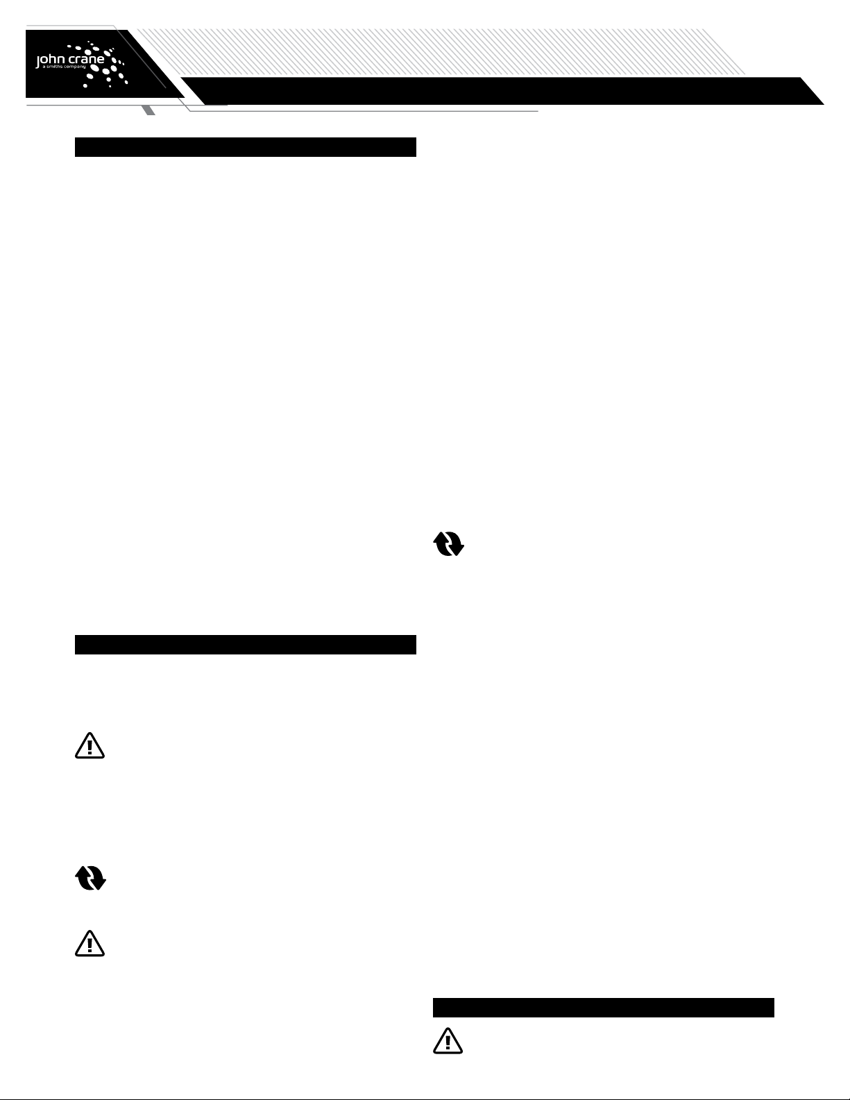
Some mechanical seals are used in conjunction with an ancillary support
system; this is clarified either by the flush plan description on the seal
arrangement drawing or by contacting John Crane (also see Section 10).
It is important for the safe function of the seal that the support system
is assembled and incorporated into the machine before operation. This
manual should be read in conjunction with the appropriate documentation
for auxiliary systems and rotating machinery.
Alarm systems are often included in the ancillary support
system and the operator must ensure appropriate action
is taken promptly in the event of an alarm.
Maintenance with steel tools must be avoided in the presence of
substances classed as explosive group IIc according to
EN 60079-0:2012+A11:2013.
If the machine is being used in a EN 60079-0:2012+A11:2013 Zone 21 or
22, regular cleaning of dust from exterior surfaces is required.
4. Declaration of Incorporation (2006/42/EC)
For each standard product supplied into the EU a Technical File is
required and a Technical Record Sheet, satisfying the needs of 2006/42/
EC. When requested, a Declaration of Incorporation (for which a Technical
File exists) will be raised and signed by a John Crane appointed
representative.
5. Transportation and Storage
Transport and store the seal in its original packaging. To ensure
seals remain in good condition they should be stored in the following
environment:
1. Dry and dust-free
2. Ventilated at room temperature
3. Protected from direct effects of heat and ultraviolet light
4. All the elastomers used in the mechanical seal have a minimum shelf
life of 5 years except for butyl rubber which has a minimum shelf life
of 2 years. We recommend that the elastomers be replaced at these
intervals. It is also recommended that the elastomer replacement be
carried out by John Crane personnel.
If used seal parts are to be shipped they must be
cleaned and decontaminated before shipping. It is the
responsibility of the machine user to ensure that any
parts being shipped have appropriate safe-handling
instructions externally attached to the package. Without
this information there will be a refusal to handle the
goods. If required a decontamination/transportation
certificate is available from John Crane. Refer to
document EDS1001.
For additional information on transportation and storage, contact your
local John Crane facility and request a copy of of document I-Storage.
If any machine with an installed component seal has been stored with
preservatives, before putting it back into operation the seal must be
removed, cleaned and dried. Particular attention must be applied to the
cleanliness of the faces and condition of the elastomers. For an installed
cartridge seal we recommend returning the complete cartridge to John
Crane for cleaning.
ATTENTION Ensure preservatives and cleaning agents do not affect
the elastomers.
ATTENTION Once the seal is fitted on the machine and the position
is set using setting devices do not re-engage them for
transportation and storage.
6. Seal Installation
Refer to the appropriate seal family installation instructions. Do not
excessively compress the seal before or during installation.
7. Before Starting the Equipment
1. Check the machine at the coupling for proper alignment of the driver
or motor.
2. Ensure that the gland plate nuts/bolts are securely tightened
according to the pump manual instructions, and all screws are
securely fastened.
3. Assemble the machine, ensure any setting spacers are removed from
the seal and turn the shaft (by hand if possible) to ensure free rotation.
4. Consult all available equipment operating instructions to check for
correctness of all piping and connections, particularly regarding seal
recirculation/flush, heating or cooling requirements, and services
external to the seal. See Section 10. Ensure all unused ports are
correctly plugged.
ATTENTION This mechanical seal is designed to operate in a liquid,
so the heat energy it creates is adequately removed.
The following check should be carried out not only after
seal installation, but also after any period of equipment
inactivity.
5. Check that the seal chamber fluid lines are open and free of any
obstruction, and ensure that the seal chamber is properly vented and
filled with liquid — refer to the pump instruction manual.
ATTENTION Except for dry running or gas lubricated seals which are
designed to operate without liquid, wet seals that are
operated without adequate liquid lubrication will often
give rise to a squealing noise from the seal area and
result in overheating and scoring or other damage to
the sealing surfaces, causing excessive emissions and a
reduced seal life.