5. If the pumped fluid is hazardous or toxic, appropriate precautions
must be taken to ensure that any seal leakage is adequately
contained. Further information on sealing hazardous or toxic fluids
should be obtained from John Crane prior to seal installation.
6. Fluorocarbon components should never be burned or incinerated
as the fumes and residues are highly toxic. If fluorocarbons are
accidentally heated above 400˚C/750˚F, they can decompose.
Protective gloves should be worn as hydrofluoric acid may be present.
7. PTFE components should never be burned or incinerated as the
fumes are highly toxic.
These instructions are for the installation and operation of
a seal as used in rotating equipment and will help to avoid
danger and increase reliability. The information required
may change with other types of equipment or installation
arrangements. These instructions must be read in
conjunction with the instruction manuals for both the
pump and any ancillary equipment.
If the seal is to be used for an application other than that originally
intended or outside the recommended performance limits, John Crane
must be contacted before its installation and use.
Any warranty may be affected by improper handling, installation, or use
of this seal. Contact John Crane for information as to exclusive product
warranty and limitations of liability.
If questions or problems arise, contact your local John Crane representative
or the original equipment manufacturer, as appropriate.
John Crane mechanical seals are precision products and
must be handled appropriately. Take particular care to
avoid damage to lapped sealing faces and to flexible
sealing rings. Do not excessively compress the seal
before or during installation.
Safety Instructions
1. The following designations are used in the installation instructions to
highlight instructions of particular importance.
NOTE: Refers to special information on how to install or
operate the seal most efficiently.
Refers to special information or instructions directed
towards the prevention of damage to the seal or its
surroundings.
Refers to mandatory instructions designed to
prevent personal injury or extensive damage to the
seal or its surroundings.
2. Installation, removal and maintenance of the seal must be carried out
only by qualified personnel who have read and understood these
installation instructions.
3. The seal is designed exclusively for sealing rotating shafts. The
manufacturer cannot be held liable for use of the seal for purposes
other than this.
4. The seal must only be used in technically perfect condition and
must be operated within the recommended performance limits in
accordance with its designated use set out in these installation
instructions.
Dry-running - often indicated by a squealing noise from
the seal area - will cause overheating and scoring or other
damage to the sealing surfaces, resulting in excessive
leakage or a much shortened seal life.
Before start-up, ensure that all personnel and
assembly equipment have been moved to a safe
distance so there is no contact with rotatin parts
on the pump, seal, couplin , or motor.
WARNING: Seal installation should be handled only by qualified
personnel. If questions arise, contact the local
John Crane representative. Improper use and/or
installation of this product could result in injury to
the person and/or harmful emissions to
the environment, and may affect any warranty
on the product. Please contact John Crane for
information as to exclusive product warranty
and limitations of liability.
Before Startin the Equipment
1. Check the pump at the coupling for proper alignment of the driver
or motor.
2. Ensure that the gland plate nuts/bolts are securely tightened
according to the pump manual instructions, and that all screws are
securely fastened.
3. Complete the assembly of the pump, and turn the shaft (by hand if
possible) to ensure free rotation.
4. Consult all available equipment operating instructions to check for
correctness of all piping and connections, particularly regarding seal
recirculation/flush, heating or cooling requirements, and services
external to the seal.
This mechanical seal is designed to operate in a liquid
so the heat energy it creates is adequately removed.
Therefore, the following check should be carried out
not only after seal installation, but also after any
period of equipment inactivity.
5. Check that the seal chamber fluid lines are open and free of any
obstruction, and ensure that the seal chamber is properly vented
and filled with liquid - refer to the pump instruction manual.
ATTENTION
ATTENTION
ATTENTION
!
ATTENTION
ATTENTION
!
Foreword
These instructions are provided to familiarize the user with the seal
and its designated use. The instructions must be read and applied
whenever work is done on the seal, and must be kept available for
future reference.
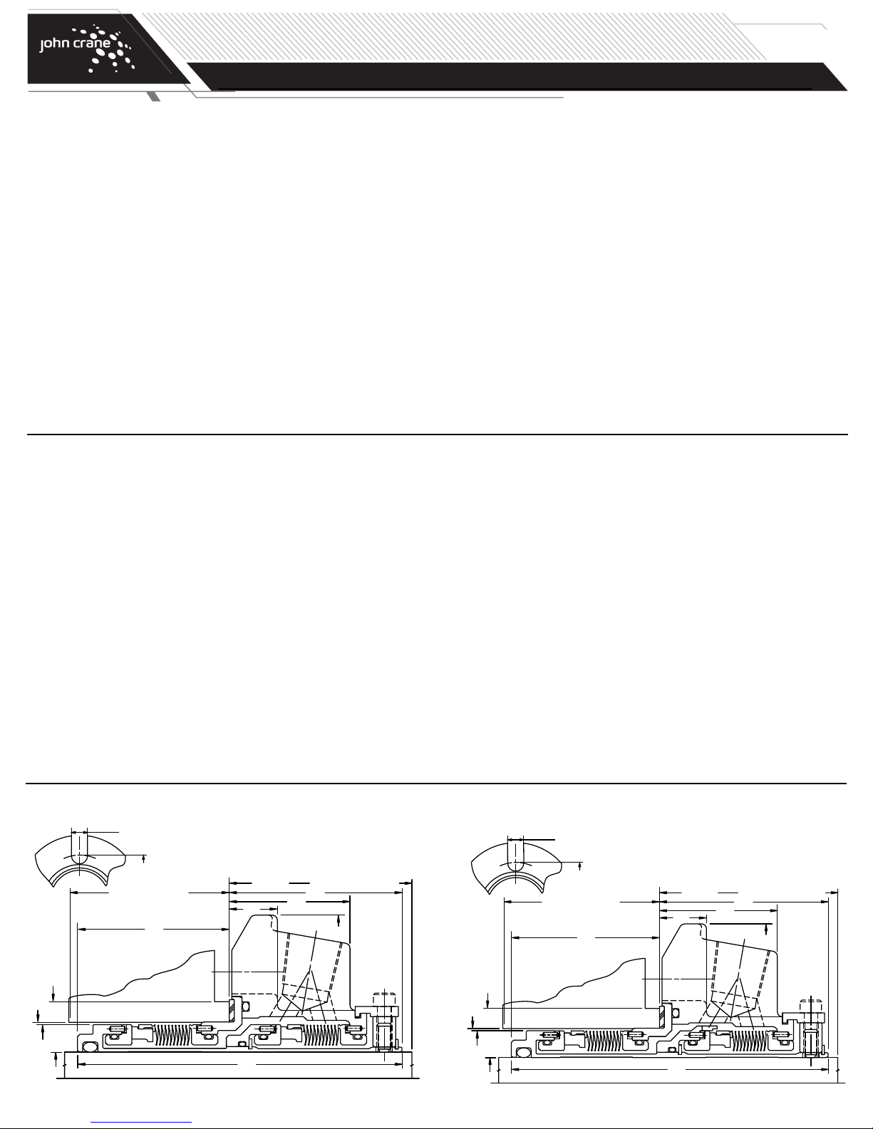
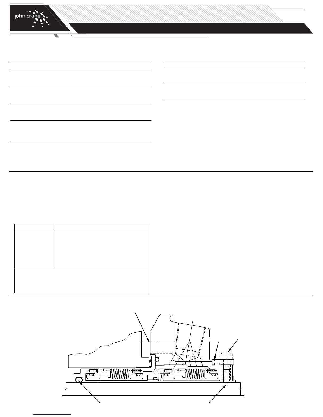
TYPE 5625/5625P
DUAL METAL BELLOWS CARTRIDGE SEAL
Installation, Operation & Maintenance Instructions
PAGE 1