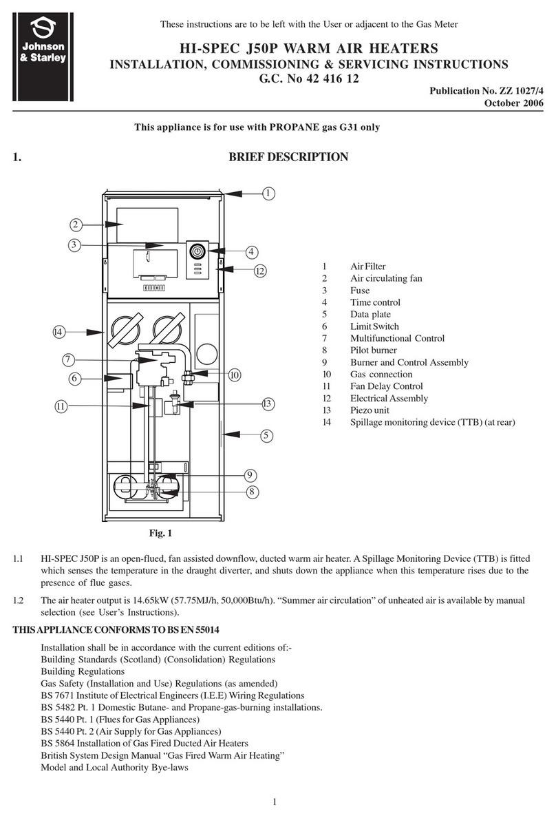
Installation shall be in accordance with the current editions of:-
Building Standards (Scotland) (Consolidation) Regulations
Building Regulations
Gas Safety (Installation and Use) Regulations (as amended)
BS 7671 Institute ofElectrical Engineers (I.E.E.) Wiring Regulations
BS 6891 Installation of Low Pressure Gas Pipework of up to 28mm (R1) in domestic premises (2nd family gases).
BS 5440 Pt. 1 (Flues for Gas Appliances)
BS 5440 Pt. 2 (Air Supply for Gas Appliances)
BS 5864 Installation of Gas Fired Ducted Air Heaters
British System Design Manual “Gas Fired Warm Air Heating”
Model and Local Authority Bye-laws
BS 5546 Installation of Domestic Hot Water Supplies.
IMPORTANT: STATUTE LAWDEFINES THATALLGAS APPLIANCES MUSTBE INSTALLED BYCOMPETENT
PERSONS, (i.e. CORGI REGISTERED INSTALLERS) IN ACCORDANCE WITH THE GAS SAFETY
(INSTALLATION AND USE) REGULATIONS (CURRENT EDITION). FAILURE TO COMPLY WITH THESE
REGULATIONSMAYLEADTOPROSECUTION.
2. HEATERCOMPARTMENTAND CLEARANCES(SeeBS5864)
2.1 IMPORTANT: If the heater is to be fitted to an existing base duct (warm air plenum), always ensure that installation is
carried out such that the rear left hand corner of the heater is aligned with the rear left hand corner of the base duct, so
that any overhang or blanking off will be at the front and/or right hand side. In any event, blanking plates must be
mechanically secured and all joints sealed.
2.2 When the heater is fitted into a compartment consideration should be given to the space required for the removal and
replacement of the filter tray and the entry of the gas and electrical supplies.
2.3 For service access, a minimum of 500mm (20ins) is required at the front of the heater. Space must also be allowed, in a
compartment installation, to permit the removal of the heater. The clearance between the appliance and the compartment
should be not less than 75mm (3 in). However, if clearances are less than 75mm, the internal surface of the
compartment must be lined with non-combustible material. The compartment must be of a fixed rigid structure.
2.4 In airing cupboard installations, the part used as the air heater compartment must comply with the relevant section of
BS5864 and must be completely separated by either a non-combustible partition or a perforated metal partition with the
perforations not exceeding 13mm (1/2in). The secondary flue must be a tight fit where it passes through the partition and
must be suitably protected (see BS 5440:Part 1).
2.5 In under-stairs installations, the compartment must comply with the relevant section of BS 5864, provided that in
addition, all internal surfaces, including the base, are non-combustible or lined with non-combustible material. This
requirement is applicable only to dwellings of more than two storeys. Combustible floors must be insulated from the
heater.
2.6 In free-standing installations, (see instructions packed with free standing kit), only one or two walls will be in contact
with the air heater and therefore complying with the relevant section of BS 5864.
2.7 If theAir Heater is to be installed onto a combustible surface, a suitable base tray (BT40) is required. However, when a base
duct is used, this provides sufficient insulation, and no insulation is required.
2.8 Fir Slot Fix applications (see instructions packed with the Slot Fix Kit), it is important to ensure that the draught diverter
relief is maintained on both sides of the application.
3. VENTILATIONANDCOMBUSTIONAIR
3.1 The room or internal space in which the heater is installed requires a permanent air vent of minimum effective area
62cm2 (9in2). The air vent should be either direct to outside air or to an adjacent room or internal space (other than a
toilet or bathroom) that itself has an equivalent air vent direct to outside.
Note: The above minimum area assumes that an ELJAN 6 circulator is fitted.
3.2 Combustion air may be introduced, via a 127mm (5in) nominal bore pipe, connected to a return air duct or plenum from
a ventilated area and fitted with a lockable damper. The damper should be adjusted to control combustion airflow to
0.0108m3/s (22.9cfm), (i.e. 0.95m/s[165ft/min] velocity in a 127mm[5in] bore pipe). Ifthisarrangement is used, anon-
closeable warm air register MUST be provided in the same area as the front of the air heater or heater compartment if a return
air grille is not located in that area.
3.3 When installed in a compartment, two permanent ventilation openings into the compartment are required, one at high
level and one at low level, both communicating either directly with outside air or with a ventilated room or space. The
minimum effective areas specified in Table 1 are related to the rated heat input of the Air Heater, and assuming that an
ELJAN 6 circulator is fitted.
3.4 If any room or area from which air is drawn for ventilation or combustion contains an extract fan, the permanent vents
must be sized to ensure that the operation of the appliance(s) at full rate is/are not adversely affected.A spillage test as
specified in sub-para 6.8 (Safety Checks) is carried out and any remedial work undertaken.
2
Fig.7b,BASICCONTROLFUNCTIONALDIAGRAM
Fig.6a,SYSTEME-TCIRCUITDIAGRAM
Fig.6b,BASICCONTROLCIRCUITDIAGRAM
Fig.8,PRINCIPALDIMENSIONS(mm)
10. SHORTLISTOFSPARES
HI-SPECJ40
KEY G.CNo MFR’SNo DESCRIPTION QTY
1 245502 1000-0516580 Fan Assembly 1
2 381627 1000-0701140 Multifunctional Control (S.I.T. Nova) 1
232903 BOS02061 O RingSeal 2
3 A432-0852000 Pilot Mounting Bracket 1
173096 1000-0704810 Pilot BurnerAssembly 1
381712 1000-0705140 Pilot Injector 1
S01496 Pilot Feed Pipe Kit 1
395676 1000-0701800 HookNut4mm 1
386775 1000-0701790 HookOlive 4mm 1
386775 BOS01970 Igniter Electrode 1
387819 BOS02394 Igniter Lead 1
381626 1000-0704830 Thermocouple 1
382775 1000-0701810 ShearOff 4mm 1
244898 BOS02406 Electrode Retaining Nut 1
4 378466 BOS02031 TimeControl 1
5 245526 A432-0760000 Burner and ControlsAssembly 1
245526 A4300/0751 Main BurnerArm 1
6 E00409 1000-0700270 MainInjector(Bray 23/1050) 1
7 395945 1000-0700570 PiezoUnit (High Energy) 1
8 245509 1000-0513820 Fuse T3.15A anti-surge 1
9 A432-0182000 FilterTray 1
10 364835 S00832 SolenoidValve 1
11 A4300/0300WE HeatExchanger 1
12 245542 1000-0515970 Capacitor15 uF 1
13 245500 1000-0516010 SpillageMonitor Device (TTB) upto (& inc) serialNo: 16001719 1
E83-211 1000-0521880 SpillageMonitorDevice(TTB)fromserial No: 16001720 1
A432-0161000 LowerCabinet Door 1
SystemE-TModelsonly
14 245513 ET004 Electronic PanelAssembly with daughter board 1
15 245514 1000-0515620 Thermista-stat 1
16 245516 1000-0516370 FanDelayControl/Limit Switch 1
17 E05328 1000-0515090 Mains Filter 1
A432-0157000 FanChamber Door 1
BasicModelsonly
18 245524 1000-0501000 ElectricalPanelAssembly 1
19 245521 1000-0516360 FanDelayControl/Limit Switch 1
20 245523 1000-0516540 Transformer Fan Speed 1
21 245525 1000-0515730 Transformer24 volt 1
22 245413 1000-0511760 Relay Module 1
245423 1000-0502240 Fuse T500mA anti-surge 1
A432-0156000 FanChamber Door 1
27
