manuals.online logo
Brands
  1. Home
  2. •
  3. Brands
  4. •
  5. Johnson Controls
  6. •
  7. Control Unit
  8. •
  9. Johnson Controls System 350 Y350R Service manual

Johnson Controls System 350 Y350R Service manual

FANs 930, 930.5, 125
Product/Technical Bulletin Y350R
Issue Date 0598
© 1998 Johnson Controls, Inc. 1
Part No. 24-7664-214, Rev. D
Code No. LIT-930090
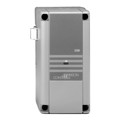
The Y350R is a rectified Class 2, 24 VAC power
supply module designed specifically for use with
System 350™ Modular Control Systems.
As with all System 350 products, the Y350R is housed
in a compact NEMA 1, high-impact plastic enclosure.
The modular design provides easy, plug-in
connections for quick installation and future
expandability.
Figure 1: Y350R Power Module
System 350Y350R Power Module
Features and Benefits
❑Modular Design Enables stage, display, and power modules to be
purchased and installed as necessary
❑Plug-in Connectors and
35 mm DIN Rail Mounting Eliminates wiring between modules and reduces
installation costs
❑Accepts Input Voltages of
120 or 240 VAC, 50/60 Hz Reduces inventory by encompassing the primary
voltage requirements
2 Y350R Power Module Product/Technical Bulletin
A
pplication
The Y350R Power Module provides the power
necessary to operate all System 350 controls and
add-on modules. For system capabilities, see Table 1.
Table 1: Maximum Number of Add-on
Modules when Powered by a Y350R
Control
Module Stage Module Display
Module
A350A
A350B
A350E
9 S350A’s or S350C’s
6 S350A’s or S350C’s with
1 S350P
4 S350A’s or S350C’s with
2 S350P’s
1 D350
A350P 4 S350A’s or S350C’s
2 S350A’s or S350C’s with
1 S350P
1 D350
A350R
A350S 9 S350A’s or S350C’s
6 S350A’s or S350C’s with
1 S350P
4 S350A’s or S350C’s with
2 S350P’s
2 D350
W351A 5 S351’s 1 D351
W351P 4 S351’s 1 D351
P352A 5 S352’s 1 D352
P352P No additional stages available 1 D352
R353 5 S353’s No
display
available
All System 350 add-on modules snap on to a DIN rail
and plug into the control and to each other via 5-pin
connectors. Add-on modules can be arranged in any
order and there is no wiring required to interconnect
the System 350 components.
O
peration
The Y350R operates from 240 VAC or 120 VAC
power. A 24 VAC, Class 2, step-down transformer
brings the voltage to a level which the System 350
modules will accept. There are no adjustments for the
power module.
IMPORTANT: All Series Y350R Power Modules
are designed for use only in
conjunction with operating
controls. Where an operating
control failure would result in
personal injury and/or loss of
property, it is the responsibility of
the installer to add devices
(safety, limit controls) that protect
against, or systems (alarm,
supervisory systems) that warn
of, control failure.
D
imensions
Mounting Slot (4)
for No. 6 Screws
Y350
Conduit
Hole
0.145
3.68
2.94
75
DIN Rail
Mount 2.40
61
1.20
31
0.85
21.6
0.42
1.56
40
0.5
13
5.00
127
2.40
61
0.875
22
Figure 2: Y350R Dimensions, mm/in.
I
nstallation and Wiring
The Y350R case has provisions for mounting to a
standard 35 mm DIN rail, or can be mounted using the
four key slot mounting holes located in the rear of the
case.
Mount System 350 modules in any convenient location
using either the DIN rail mounts or the mounting holes
located on the back of the control case. The
components are not position sensitive, but should be
mounted so they can be easily wired and adjusted.
Y350R Power Module Product/Technical Bulletin 3
IMPORTANT: All wiring must be installed to
conform to the National Electrical
Code and local regulations.
1. Secure the module to the DIN rail, wall, or panel.
!
WARNING:Electrical Shock Hazard.
Disconnect power supply before
modules are interconnected and
wiring connections are made to
avoid possible electrical shock or
damage to the equipment.
2. Connect input wiring to the Y350R power module.
Strip approximately 3/8 inch from the wire
insulation, insert the wire under each terminal
screw, and tighten. (See Figure 3.)
Note: If conduit is used when installing System 350
components, be sure to connect the hub to the
conduit before the hub is secured to the
enclosure.
Module
Connector
Module
Connector
240 VAC COM 120 VAC
Power Input Terminals
Figure 3: Interior of the Y350R Power
Module
C
heckout Procedure
Before applying power, make sure installation and
wiring connections are according to job specifications.
After necessary adjustments and electrical
connections have been made, put the system in
operation and observe at least three complete
operating cycles before leaving the installation.
T
roubleshooting
If the control system does not function properly and
the Y350R is suspect, proceed as follows:
1. Connect a Digital Voltmeter (DVM) between the
24V (+) and COM (-) terminals located on the
control module’s left-side connector. (Terminal
designations are marked on the control module.)
2. Select DC volts on the DVM and verify that the
voltage is between 16 and 38 VDC. If the DVM
reading is within range, the Y350R is functioning
properly.
Note: Consult the
Troubleshooting
section of the
appropriate control bulletin for a complete
system troubleshooting procedure.
3. If the DVM reading is not within the indicated
voltage range, check wiring and correct if
necessary. If the wiring is correct and the reading
remains out of range, replace the Y350R.
R
epairs and Replacement
Field repairs or calibration must not be made.
Replacement modules are available through the
nearest Johnson Controls representative. (See Table
2.)
O
rdering Information
Table 2: Product Available
Item Product Code Description
Power Module Y350R-1C Rectified, Class 2, 24 VAC Power Supply
4 Y350R Power Module Product/Technical Bulletin
S
pecifications
Product Y350R Power Module
Input Voltage 120/240 VAC, 50/60 Hz
Output Voltage Rectified 24 VAC, 10 VA, Class 2
Material Case and cover: NEMA 1 high-impact plastic
Ambient Temperature Operating: -34 to 66°C (-30 to 150°F)
Shipping: -40 to 85°C (-40 to 185°F)
Ambient Humidity 0 to 95% RH non-condensing
Mounting Wall or DIN rail
Agency Listing UL Guide No. XAPX, File E27734
CUL Guide No. XAPX7, File E27734
CSA Class No. 4813 02, File LR948
The performance specifications are nominal and conform to acceptable industry standards. For application at conditions beyond these specifications,
consult the local Johnson Controls office. Johnson Controls, Inc. shall not be liable for damages resulting from misapplication or misuse of its products.
Controls Group
507 E. Michigan Street
P.O. Box 423
Milwaukee, WI 53201 Printed in U.S.A.

Other Johnson Controls Control Unit manuals
Johnson Controls METASYS NU-XBN101-0 User manual

Johnson Controls

Johnson Controls METASYS NU-XBN101-0 User manual

Johnson Controls A19 Series User manual

Johnson Controls

Johnson Controls A19 Series User manual

Johnson Controls Tyco DV-5a Series User manual
Johnson Controls

Johnson Controls Tyco DV-5a Series User manual

Johnson Controls F4-XPM Series User manual

Johnson Controls

Johnson Controls F4-XPM Series User manual

Johnson Controls System 450 Series Operation and maintenance manual

Johnson Controls

Johnson Controls System 450 Series Operation and maintenance manual

Johnson Controls Penn A19K Series User manual

Johnson Controls

Johnson Controls Penn A19K Series User manual

Johnson Controls S300 Series Assembly instructions

Johnson Controls

Johnson Controls S300 Series Assembly instructions

Johnson Controls IOM3723 User manual

Johnson Controls

Johnson Controls IOM3723 User manual

Johnson Controls H Series User manual

Johnson Controls

Johnson Controls H Series User manual

Johnson Controls GH-5000 User manual

Johnson Controls

Johnson Controls GH-5000 User manual

Johnson Controls CKM-F8P Manual

Johnson Controls

Johnson Controls CKM-F8P Manual

Johnson Controls METASYS TC-9102 Series Service manual
Johnson Controls

Johnson Controls METASYS TC-9102 Series Service manual

Johnson Controls VP140 L Series User manual

Johnson Controls

Johnson Controls VP140 L Series User manual

Johnson Controls PENN P70 Series Manual

Johnson Controls

Johnson Controls PENN P70 Series Manual

Johnson Controls A19ZBC Series Service manual
Johnson Controls

Johnson Controls A19ZBC Series Service manual

Johnson Controls V43 Series Manual

Johnson Controls

Johnson Controls V43 Series Manual

Johnson Controls TYCO DPV-1 Instruction manual

Johnson Controls

Johnson Controls TYCO DPV-1 Instruction manual

Johnson Controls System 450 Series User manual

Johnson Controls

Johnson Controls System 450 Series User manual

Johnson Controls Penn System 450 Series User manual

Johnson Controls

Johnson Controls Penn System 450 Series User manual

Johnson Controls Tyco RSV-1 User manual

Johnson Controls

Johnson Controls Tyco RSV-1 User manual

Johnson Controls UL Listed GS-20 Series User manual
Johnson Controls

Johnson Controls UL Listed GS-20 Series User manual

Johnson Controls Tyco HSM3408 User manual

Johnson Controls

Johnson Controls Tyco HSM3408 User manual

Johnson Controls VG7000 Series User manual

Johnson Controls

Johnson Controls VG7000 Series User manual

Johnson Controls Mercury P2000 CKM-MR16IN Manual

Johnson Controls

Johnson Controls Mercury P2000 CKM-MR16IN Manual

Popular Control Unit manuals by other brands

Watts AMES LF920GD Series Specification, Installation, and Adjustments Manual

Watts

Watts AMES LF920GD Series Specification, Installation, and Adjustments Manual

Lumin LSPFN13WLAN instruction manual

Lumin

Lumin LSPFN13WLAN instruction manual

Pilz PIT es Set10u-5c PCB operating manual

Pilz

Pilz PIT es Set10u-5c PCB operating manual

PERSTA DRI 21 operating instructions

PERSTA

PERSTA DRI 21 operating instructions

Siemens SIMATIC ET 200SP manual

Siemens

Siemens SIMATIC ET 200SP manual

Ponar WE6 Series Operation manual

Ponar

Ponar WE6 Series Operation manual

Genius LYNX 06 manual

Genius

Genius LYNX 06 manual

PVA FCS300 Series Operation manual

PVA

PVA FCS300 Series Operation manual

Wöhner CRITO CrossBoard manual

Wöhner

Wöhner CRITO CrossBoard manual

Bticino F3N400 installation manual

Bticino

Bticino F3N400 installation manual

Renogy RNGBTCM001 user manual

Renogy

Renogy RNGBTCM001 user manual

Andrew ION-B Series user manual

Andrew

Andrew ION-B Series user manual

Duco DucoBox Focus quick start

Duco

Duco DucoBox Focus quick start

GEM 693 manual

GEM

GEM 693 manual

Tyco DV-5A manual

Tyco

Tyco DV-5A manual

Lindab Airy Assembly instructions

Lindab

Lindab Airy Assembly instructions

Honeywell VS8521 installation instructions

Honeywell

Honeywell VS8521 installation instructions

Exhausto VEX200 series Original instructions

Exhausto

Exhausto VEX200 series Original instructions

manuals.online logo
manuals.online logoBrands
  • About & Mission
  • Contact us
  • Privacy Policy
  • Terms and Conditions

Copyright 2025 Manuals.Online. All Rights Reserved.