manuals.online logo
Brands
  1. Home
  2. •
  3. Brands
  4. •
  5. Johnson Controls
  6. •
  7. Irrigation System
  8. •
  9. Johnson Controls tyco RFII-MRI Series User manual

Johnson Controls tyco RFII-MRI Series User manual

Series RFII-MRI — 5.6 K-factor
Non-Magnetic Concealed Pendent Sprinklers
Quick & Standard Response, Standard Coverage
Page 1 of 4 JULY 2020 TFP182
IMPORTANT
Refer to Technical Data Sheet
TFP2300 for warnings pertaining to
regulatory and health information.
Always refer to Technical Data
Sheet TFP700 for the “INSTALLER
WARNING” that provides cautions
with respect to handling and instal-
lation of sprinkler systems and com-
ponents. Improper handling and
installation can permanently damage
a sprinkler system or its compo-
nents and cause the sprinkler to fail
to operate in a fire situation or cause
it to operate prematurely.
Worldwide
Contacts
www.tyco-fire.com
General
Description
The TYCO Series RFII-MRI 5.6 K-fac-
tor, Non-Magnetic Concealed Pendent
Sprinklers Quick Response (3 mm bulb)
and Standard Response (5 mm bulb),
are decorative sprinklers featuring a
flat cover plate designed to conceal
the sprinkler.
The RFII-MRI Sprinkler is intended for
use inside of the MRI environment, that
is, in the MR system room and close to
the scanner unit. However, this sprin-
kler is not intended for use directly
inside of the MR system, such as within
the bore of the scanner unit. During
the intended use, the RFII-MRI Sprin-
kler must be mounted at the ceiling to
the fixed fire protection piping system
of the MR system room. Under these
conditions, per non-clinical testing to
ASTM F2052-15, the RFII-MRI Sprin-
kler was found to be acceptable for use
under a static magnetic field of 7-Tesla
or less. Standard MRI apparatus are
typically in the 3 Tesla range.
Each sprinkler is comprised of sepa-
rately ordered components: a Cover
Plate/Retainer Assembly and a Sprin-
kler/Support Cup Assembly. The sep-
arable, two-piece assembly design
provides the following benefits:
• Allows installation of the sprinklers
and pressure testing of the fire pro-
tection system prior to installation of
a suspended ceiling or application of
the finish coating to a fixed ceiling.
• Permits the removal of suspended
ceiling panels for access to building
service equipment without having
to first shut down the fire protection
system and remove sprinklers.
• Provides for 1/2 in. (12,7 mm) of ver-
tical adjustment to allow a measure
of flexibility in determining the length
of fixed piping to cut for the sprinkler
drops.
The RFII-MRI Sprinklers are shipped
with a Disposable Protective Cap. The
Protective Cap is temporarily removed
during installation and replaced to help
protect the sprinkler during ceiling
installation or finish. The tip of the Pro-
tective Cap can be used to mark the
center of the ceiling hole into plaster
board or ceiling tiles by gently pushing
the ceiling product against the Pro-
tective Cap. When ceiling installa-
tion is complete, the Protective Cap is
removed and the Cover Plate/Retainer
Assembly is installed.
As an option, the RFII-MRI Standard
Response (5 mm bulb) Sprinkler can
be fitted with a silicone Air and Dust
Seal, see Figure 5. The Air and Dust
Seal is intended for sensitive areas
where it is desirable to prevent air and
dust from the area above the ceiling to
pass through the cover plate.
NOTICE
The RFII-MRI Sprinklers described
herein must be installed and main-
tained in compliance with this docu-
ment and with the applicable standards
of the NATIONAL FIRE PROTECTION
ASSOCIATION (NFPA), in addition to
the standards of any authorities having
jurisdiction. Failure to do so may impair
the performance of these devices.
The owner is responsible for maintain-
ing their fire protection system and
devices in proper operating condition.
The installing contractor or sprinkler
manufacturer should be contacted with
any questions.
Sprinkler
Identification
Number (SIN)
TY3530 — 3 mm bulb
TY3550 — 5 mm bulb
TFP182
Page 2 of 4
Technical
Data
Sprinkler Approvals
TY3530 (3 mm bulb)
• UL Listed, C-UL listed as quick
response
• FM approved as standard response
TY3550 (5 mm bulb)
• UL listed, C-UL listed, and FM approved
as standard response
Note: FM does not approve concealed
sprinklers for quick response.
Note: Approvals apply only to the service
conditions indicated in the Design Criteria
section.
Air and Dust Seal Approvals
UL and C-UL Listed
Standard Response (TY3550) application
only
Maximum Working Pressure
Maximum 175 psi (12,1 bar)
Temperature Rating
155°F (68°C) Sprinkler with
139°F (59°C) Plate
200°F (93°C) Sprinkler with
165°F (74°C) Plate
Discharge Coefficient
K= 5.6 GPM/psi½(80,6 LPM/bar½)
Adjustment
1/2 in. (12,7 mm)
Finishes
See the Ordering Procedure section.
Physical Characteristics
Frame . . . . . . . . . . . . . . . . . . . . . . . . . . . .Bronze
Support Cup . . . . . . . . . . . . . . . . . . . . . . . .Brass
Guide Pins. . . . . . . . . . . . . . . . . . Stainless Steel
Deflector . . . . . . . . . . . . . . . . . . . . . . . . . .Bronze
Compression Screw . . . . . . . . . . . . . . . . . .Brass
Bulb . . . . . . . . . . . . . . . . . . . . . . . . . . . . . . . Glass
Cap .....................Bronze or Copper
Sealing Assembly ..Beryllium Nickel w/TEFLON
Cover Plate . . . . . . . . . . . . . . . . . . . . . . . . .Brass
Retainer. . . . . . . . . . . . . . . . . . . . . . . . . . . .Brass
Ejection Spring . . . . . . . . . . . . . . Stainless Steel
Design
Criteria
The Series RFII-MRI Concealed
Pendent Sprinklers are intended for
fire protection systems designed in
accordance with the standard installa-
tion rules recognized by the applicable
Listing or Approval agency; for example,
UL Listing is based on NFPA 13.
The RFII-MRI Sprinklers are only listed
with the Series RFII-MRI Concealed
Cover Plates having a factory applied
finish.
NOTICE
Do not use the RFII-MRI Sprinklers in
applications where the air pressure
above the ceiling is greater than that
below. Down drafts through the Sprin-
kler/Support Cup Assembly can delay
sprinkler operation in a fire situation.
Operation
When exposed to heat from a fire, the
Cover Plate, normally soldered to the
Retainer at three points, falls away to
expose the Sprinkler/Support Cup
Assembly.
The Deflector — supported by the
Guide Pins — then drops down to its
operational position.
The glass bulb contains a fluid that
expands when exposed to heat. When
the rated temperature is reached, the
fluid expands sufficiently to shatter the
glass bulb, activating the sprinkler and
allowing water to flow.
Installation
The Series RFII-MRI Concealed
Pendent Sprinklers must be installed
in accordance with this section.
General Instructions
Do not install any bulb-type sprin-
kler if the bulb is cracked or there is
a loss of liquid from the bulb. With the
sprinkler held horizontally, a small air
bubble should be present. The diam-
eter of the air bubble is approximately
1/16 in. (1,6 mm) for the 155°F (68°C)
and 3/32 in. (2,4 mm) for the 200°F
(93°C) temperature ratings.
A leak-tight 1/2 in. NPT sprinkler joint
should be obtained by applying a
minimum to maximum torque of 7 to
14 lb-ft (9,5 to 19,0 N·m). Higher levels
of torque can distort the sprinkler Inlet
with consequent leakage or impairment
of the sprinkler.
Do not attempt to compensate for
insufficient adjustment in the Sprinkler
SPRINKLER/SUPPORT CUP
ASSEMBLY
COVER PLATE/RETAINER
ASSEMBLY
GUIDE
PINS (2)
DEFLECTOR
(DROPPED
POSITION)
COMPRESSION
SCREW
DEFLECTOR
SUPPORT
CUP WITH
ROLL FORMED
THREADS
FRAME
1/2" NPT
CAP
BULB
SEALING
ASSEMBLY
RETAINER
WITH THREAD
DIMPLES
EJECTION
SPRING
SOLDER
TABS (3)
COVER
PLATE
THREAD INTO
SUPPORT
CUP UNTIL
MOUNTING
SURFACE IS
FLUSH WITH
CEILING
FIGURE 1
SERIES RFII-MRI CONCEALED SPRINKLER
ASSEMBLY
TFP182
Page 3 of 4
A: 3-1/4 inches (82,6 mm) C: 2-3/8 to 2-5/8 inches (60,3 to 66,7 mm)
B: 3/16 inches (4,8 mm) D: 1-3/4 to 2-1/4 inches (44,5 to 57,2 mm)
by under- or over-tightening the Sprin-
kler/Support Cup Assembly. Re-adjust
the position of the sprinkler fitting to
suit.
Step 1. Install the sprinkler only in the
pendent position with the center-line
of the sprinkler perpendicular to the
mounting surface.
Step 2. Remove the Protective Cap.
Step 3. With pipe thread sealant
applied to the pipe threads, hand-
tighten the sprinkler into the sprinkler
fitting.
Step 4. Wrench-tighten the sprinkler
using only the RFII Sprinkler Wrench,
see Figure 3. Apply the RFII Sprinkler
Wrench to the Sprinkler as shown in
Figure 3.
Step 5. Replace the Protective Cap by
pushing it upwards until it bottoms out
against the Support Cup, see Figure
4. The Protective Cap helps prevent
damage to the Deflector and Arms
during ceiling installation and/or finish.
You can also use the Protective Cap to
locate the center of the clearance hole
by gently pushing the ceiling material
up against the center point of the Pro-
tective Cap.
NOTICE
As long as the Protective Cap remains
in place, the system is considered “Out
of Service”.
Step 6. After the ceiling has been
completed with the 2-1/2 in. (63,5 mm)
diameter clearance hole and in prep-
aration for installing the Cover Plate/
Retainer Assembly, remove and discard
the Protective Cap. Verify that the
Deflector moves up and down freely.
If the Sprinkler is damaged and the
Deflector does not move up and down
freely, replace the entire Sprinkler.
Do not attempt to modify or repair a
damaged sprinkler.
Step 7. When installing an Air and Dust
Seal, see Figure 5; otherwise, proceed
to Step 8. To attach the Air and Dust
Seal, verify the angle of the outside
edge of the seal is oriented accord-
ing to Figure 5. Start the edge of the
Retainer in the grooved slot of the Air
and Dust Seal and continue around the
retainer until the entire Air and Dust
Seal is engaged.
Step 8. Screw on the Cover Plate/
Retainer Assembly until the Retainer,
shown in Figure 2, or the Air and Dust
Seal, shown in Figure 5, contacts the
ceiling. Do not continue to screw on the
Cover Plate/Retainer Assembly so that
it lifts a ceiling panel out of its normal
position. If you cannot engage the
Cover Plate/Retainer Assembly with
the Support Cup or you cannot engage
the Cover Plate/Retainer Assembly suf-
ficiently to contact the ceiling, you must
reposition the Sprinkler Fitting.
COVER PLATE
PROFILE DEPTH
DIMENSION B
1/2" (12,7 mm)
THREADED
ADJUSTMENT
D
FACE OF
SPRINKLER
FITTING
MANUFACTURER
PRESET GAP
3/32" (2,4 mm)
FACE
OF CEILING,
RETAINING RING
MOUNTING
SURFACE
SPRINKLER
SUPPORT CUP
ASSEMBLY
CLEARANCE HOLE
DIAMETER
DIMENSION C
DEFLECTOR
IN DROPPED
POSITION
3/16" to 11/16"
(4,8 to 17,5 mm)
REFERENCE
COVER PLATE
RETAINER
ASSEMBLY
COVER PLATE
DIAMETER
DIMENSION A
FRAME
ARM
SUPPORT
CUP
7/8" (23 mm)
SQUARE
ACCEPTS
1/2" SOCKET
DRIVE
ALIGN
ARROWS WITH
FRAME ARMS
FIGURE 2
SERIES RFII-MRI CONCEALED SPRINKLER
INSTALLATION DIMENSIONS
FIGURE 3
SERIES RFII-MRI SPRINKLER WRENCH
TFP182
Page 4 of 4
NATIONAL FIRE PROTECTION ASSOCIATION and NFPA are registered trademarks of National Fire Protection Association;
TEFLON is a registered trademark of DuPont
1400 Pennbrook Parkway, Lansdale, PA 19446 | Telephone +1-215-362-0700
© 2020 Johnson Controls. All rights reserved. All specifications and other information shown were current as of document revision date and are subject to change without notice.
Care and
Maintenance
The Series RFII-MRI Concealed
Pendent Sprinklers must be maintained
and serviced in accordance with this
section.
Before closing a fire protection system
main control valve for maintenance
work on the fire protection system
that it controls, obtain permission to
shut down the affected fire protection
system from the proper authorities
and notify all personnel who may be
affected by this action.
Absence of the Cover Plate/Retainer
Assembly can delay sprinkler opera-
tion in a fire situation.
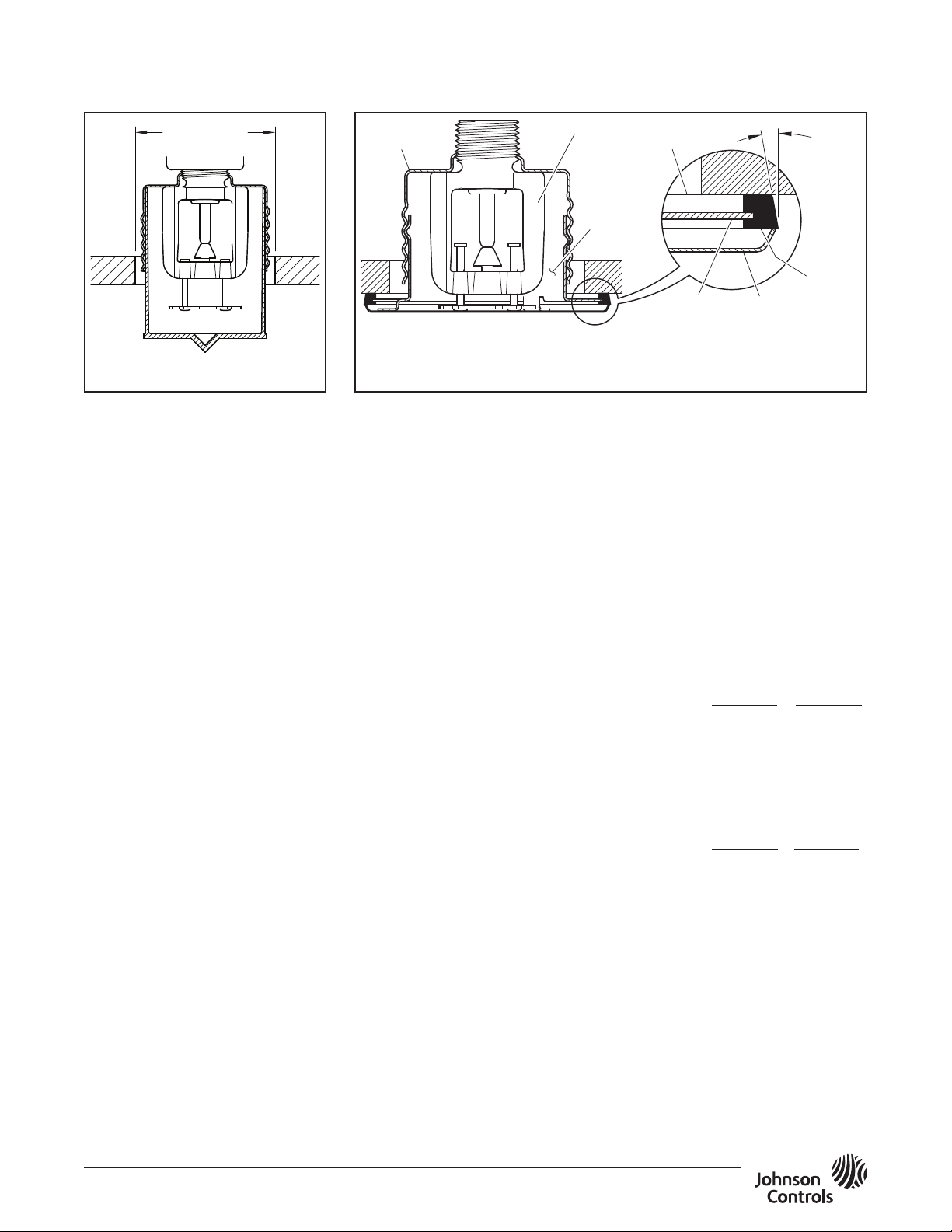
When properly installed, there is a
nominal 3/32 in. (2,4 mm) air gap
between the lip of the Cover Plate and
the ceiling, as shown in Figure 2.
This air gap is necessary for proper
operation of the sprinkler. If the ceiling
requires repainting after sprinkler
installation, ensure that the new paint
does not seal off any of the air gap.
Do not pull the Cover Plate relative to
the Enclosure. Separation may result.
Sprinklers which are found to be
leaking or exhibiting visible signs of
corrosion must be replaced.
Automatic sprinklers must never be
painted, plated, coated, or other-
wise altered after leaving the factory.
Modified sprinklers must be replaced.
Sprinklers that have been exposed to
corrosive products of combustion, but
have not operated, should be replaced
if they cannot be completely cleaned
by wiping the sprinkler with a cloth or
by brushing it with a soft bristle brush.
Exercise care to avoid damage to sprin-
klers before, during, and after instal-
lation. Replace sprinklers damaged
by dropping, striking, wrench twist-
ing, wrench slipping, or the like. Also,
replace any sprinkler that has a cracked
bulb or that has lost liquid from its bulb.
(See the Installation section.)
If you must remove a sprinkler, do not
reinstall it or a replacement without
reinstalling the Cover Plate/Retainer
Assembly. If a Cover Plate/Retainer
Assembly becomes dislodged during
service, replace it immediately.
The owner is responsible for the
inspection, testing, and maintenance of
their fire protection system and devices
in compliance with this document, as
well as with the applicable standards
of the NATIONAL FIRE PROTECTION
ASSOCIATION (NFPA) - for example,
NFPA 25 - in addition to the standards
of any other authorities having jurisdic-
tion. Contact the installing contractor
or sprinkler manufacturer regarding any
questions.
Automatic sprinkler systems should be
inspected, tested, and maintained by a
qualified Inspection Service in accor-
dance with local requirements and/or
national code.
Limited
Warranty
For warranty terms and conditions, visit
www.tyco-fire.com.
Ordering
Procedure
Contact your local distributor for
availability. When placing an order,
indicate the full product name.
Sprinkler/Support Cup Assembly
Specify: Series RFII-MRI (specify SIN),
K=5.6, Pendent Sprinkler, (specify)
temperature rating, P/N (specify):
155°F (68°C) 200°F (93°C)
TY3530 ........ 51-800-1-155 51-800-1-200
TY3550 ........ 51-801-1-155 51-801-1-200
Separately Ordered
Cover Plate/Retainer Assembly:
Specify: (temperature rating from
below) Non-Magnetic Series RFII-MRI
Concealed Cover Plate with (specify)
finish, P/N (specify):
139°F (59°C)a 165°F (74°C)b
Grey White
(RAL9002) .... 56-794-0-135 56 -794- 0-165
Brass.......... 56-794-1-135 56-794-1-165
Signal White
(RAL9003) .... 56-794-4-135 56-794-4-165
Jet Black
(RAL9005) .... 56-794-6-135 59-794-6-165
Custom ........ 56-794-X-135 56 -794-X-165
a. For use with 155°F (68°C) sprinklers.
b. For use with 200°F (93°C) sprinklers.
Sprinkler Wrench
Specify: RFII Sprinkler Wrench,
P/N 56-000-1-075
Air and Dust Seal
Specify: Air and Dust Seal,
P/N 56-908-1-001
SUPPORT
CUP
SPRINKLER
AIR
AND DUST
SEAL
COVER
PLATE
LIP OF
RETAINER
FACE OF
CEILING
ORIENT
SEAL
BEVEL AS
SHOWN
COVER
PLATE
RETAINER
ASSEMBLY
CLEARANCE
HOLE
FIGURE 5
OPTIONAL AIR AND DUST SEAL
FOR SERIES RFII-MRI (TY3550)
FIGURE 4
DISPOSABLE PROTECTIVE CAP

This manual suits for next models

2

Other Johnson Controls Irrigation System manuals

Johnson Controls tyco CHEC User manual

Johnson Controls

Johnson Controls tyco CHEC User manual

Johnson Controls tyco TY-FRL Series User manual

Johnson Controls

Johnson Controls tyco TY-FRL Series User manual

Johnson Controls tyco LFII Series Guide

Johnson Controls

Johnson Controls tyco LFII Series Guide

Johnson Controls tyco TY-FRB Series User manual

Johnson Controls

Johnson Controls tyco TY-FRB Series User manual

Johnson Controls tyco TY-FRL Series User manual

Johnson Controls

Johnson Controls tyco TY-FRL Series User manual

Johnson Controls tyco RAPID RESPONSE LFII Series User manual

Johnson Controls

Johnson Controls tyco RAPID RESPONSE LFII Series User manual

Johnson Controls tyco TY-FRB Series User manual

Johnson Controls

Johnson Controls tyco TY-FRB Series User manual

Johnson Controls tyco TY-FRB Series User manual

Johnson Controls

Johnson Controls tyco TY-FRB Series User manual

Johnson Controls tyco TY2334 User manual

Johnson Controls

Johnson Controls tyco TY2334 User manual

Johnson Controls TY5811 User manual

Johnson Controls

Johnson Controls TY5811 User manual

Johnson Controls tyco TY3334 User manual

Johnson Controls

Johnson Controls tyco TY3334 User manual

Johnson Controls tyco RFII Series User manual

Johnson Controls

Johnson Controls tyco RFII Series User manual

Johnson Controls tyco TY-FRB Series User manual

Johnson Controls

Johnson Controls tyco TY-FRB Series User manual

Johnson Controls tyco EC-5 Series User manual

Johnson Controls

Johnson Controls tyco EC-5 Series User manual

Johnson Controls tyco EC-25 User manual

Johnson Controls

Johnson Controls tyco EC-25 User manual

Johnson Controls SABROE SVER User manual

Johnson Controls

Johnson Controls SABROE SVER User manual

Johnson Controls C-9500 User manual

Johnson Controls

Johnson Controls C-9500 User manual

Johnson Controls tyco CC3 User manual

Johnson Controls

Johnson Controls tyco CC3 User manual

Johnson Controls Tyco TY720 User manual

Johnson Controls

Johnson Controls Tyco TY720 User manual

Johnson Controls tyco TY2234 User manual

Johnson Controls

Johnson Controls tyco TY2234 User manual

Johnson Controls tyco RFII Series User manual

Johnson Controls

Johnson Controls tyco RFII Series User manual

Johnson Controls DS-2 Series User manual

Johnson Controls

Johnson Controls DS-2 Series User manual

Johnson Controls Tyco RFIII User manual

Johnson Controls

Johnson Controls Tyco RFIII User manual

Johnson Controls tyco TY1234 User manual

Johnson Controls

Johnson Controls tyco TY1234 User manual

Popular Irrigation System manuals by other brands

Viking VK960 Technical data

Viking

Viking VK960 Technical data

Tyco TY-B Series quick guide

Tyco

Tyco TY-B Series quick guide

Viking FREEDOM VK486 Technical data

Viking

Viking FREEDOM VK486 Technical data

Gardena OS 140 operating instructions

Gardena

Gardena OS 140 operating instructions

Toro OSMAC E-SERIES Specifications

Toro

Toro OSMAC E-SERIES Specifications

Tyco Fire Product Star StarMax S102 instruction manual

Tyco Fire Product

Tyco Fire Product Star StarMax S102 instruction manual

Viking VK3001 Technical data

Viking

Viking VK3001 Technical data

Hunter I-25 Ultra quick start guide

Hunter

Hunter I-25 Ultra quick start guide

Tyco TY-FRB Series quick start guide

Tyco

Tyco TY-FRB Series quick start guide

Viking VK503 Technical data

Viking

Viking VK503 Technical data

Hunter I-31 Plus instructions

Hunter

Hunter I-31 Plus instructions

G-Tools G-kit Bonanza 1m2 manual

G-Tools

G-Tools G-kit Bonanza 1m2 manual

Senju Sprinkler ZN-RES manual

Senju Sprinkler

Senju Sprinkler ZN-RES manual

Autopot easy2grow 24 Set-up guidelines

Autopot

Autopot easy2grow 24 Set-up guidelines

Viking MICROFAST VK310 Technical data

Viking

Viking MICROFAST VK310 Technical data

GREENLINE EcoAqua DripSystem EADS-12 manual

GREENLINE

GREENLINE EcoAqua DripSystem EADS-12 manual

Reliable GL 112 quick start guide

Reliable

Reliable GL 112 quick start guide

Orbit WaterMaster Voyager Installation instruction

Orbit

Orbit WaterMaster Voyager Installation instruction

manuals.online logo
manuals.online logoBrands
  • About & Mission
  • Contact us
  • Privacy Policy
  • Terms and Conditions

Copyright 2025 Manuals.Online. All Rights Reserved.