Johnson MC-J6900 User manual

JOHNSON
Issue Date
2018/4/23
Edition
01
Doc No.
Revision Date
Edition
Time
2018/1
0/10
Page
47
Johnson Industries (Shanghai) Co., Ltd
MC-J6900 MASSAGE CHAIR
Service Manual
Approval
Review
Editor
Allen Sun
Allen Sun
Hans Kong

FOREWORD
Precautions during repairs and faults:
A. When disassembling, unplugging connectors and replacing parts, make sure to unplug or turn
off the power.
B. As semiconductors (IC, etc.) are prone to being damaged by static electricity, please use human
body electrostatic discharge ground wire if it is required to directly contact the baseplate when
performing operations, or touch the ground wire (ground wires of fridges, washing machines, etc.)
with bare hands to discharge the static electricity of the human body before carrying out operations.
C. The circuit baseplate mixes high voltage (AC110V, AC220V) and low voltage (12V, 5V), which
may cause electric shock accident; so please do not have direct contact without preparations.

Content
CHAPTER 1:PRODUCT SPECIFICATIONS----------------------------------------------------------------- 1
CHAPTER 2:MAINTENANCE AND STORAGE------------------------------------------------------------- 4
CHAPTER 3:ENGINEERING MODE INSTRUCTION------------------------------------------------------5
3.1 Key Operation:---------------------------------------------------------------------------------------------5
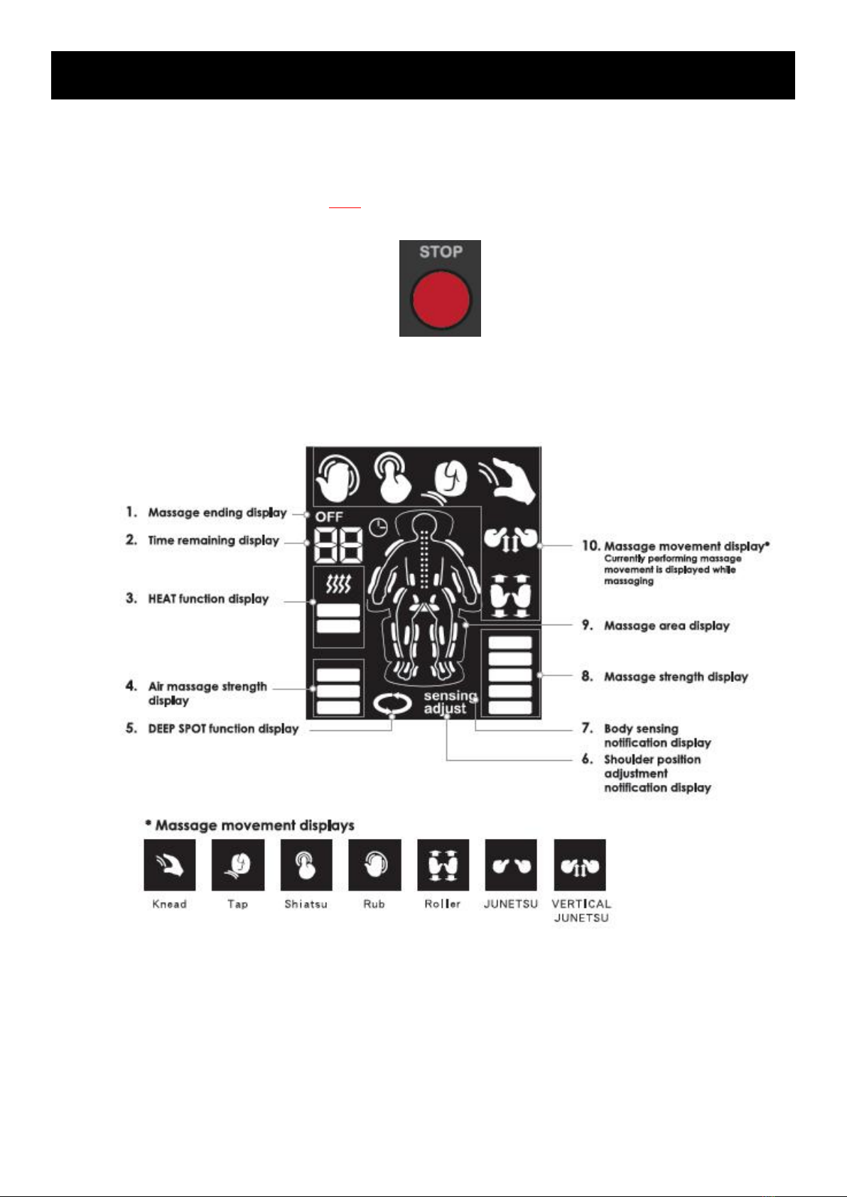
3.2 Display Information:-------------------------------------------------------------------------------------- 7
3.3 P1 Mode:---------------------------------------------------------------------------------------------------- 8
3.4 P2 Mode----------------------------------------------------------------------------------------------------- 9
3.5 P3 Mode--------------------------------------------------------------------------------------------------- 10
3.6 P4 Mode--------------------------------------------------------------------------------------------------- 11
3.7 PU Mode---------------------------------------------------------------------------------------------------12
CHAPTER 4:ERROR CODE------------------------------------------------------------------------------------ 13
CHAPTER 5:TROUBLESHOOTING-------------------------------------------------------------------------- 14
5.1 Wiring Schematic----------------------------------------------------------------------------------------14
5.2 Fail To Start----------------------------------------------------------------------------------------------- 16
5.3 Fail To Start - Continue-------------------------------------------------------------------------------- 17
5.4 Pushrod Motor Does Not Work---------------------------------------------------------------------- 19
5.5 Speak Has No Sound---------------------------------------------------------------------------------- 19
5.6 Individual Air Bag Can Not Be Inflated Or Inflated Sufficiently------------------------------19
5.7 All Air Bags Do Not Work----------------------------------------------------------------------------- 19
5.8 Abnormal Warming Function------------------------------------------------------------------------- 20
5.9 Machine Core Motor Does Not Work-------------------------------------------------------------- 22
5.10 Abnormal Key Function------------------------------------------------------------------------------ 23
5.11 Chair Back Reclines Abnormally------------------------------------------------------------------ 24
5.12 Machine Core Movement Issue--------------------------------------------------------------------24
5.13 E5 Error Code------------------------------------------------------------------------------------------ 26
CHAPTER 6:PARTS REPLACEMENT----------------------------------------------------------------------- 32
6.1 Air Pump--------------------------------------------------------------------------------------------------- 32
6.2 Machine Core-------------------------------------------------------------------------------------------- 35
6.3 Master Control Panel----------------------------------------------------------------------------------- 40
6.4 Footrest---------------------------------------------------------------------------------------------------- 41
6.5 Software Update-----------------------------------------------------------------------------------------44
6.6 Machine Breakdown Drawing------------------------------------------------------------------------ 45
CHAPTER 7:PARTS LIST--------------------------------------------------------------------------------------- 46

1
CHAPTER 1:PRODUCT SPECIFICATIONS

2
CHAPTER 1:PRODUCT SPECIFICATIONS

3
CHAPTER 1:PRODUCT SPECIFICATIONS

4
CHAPTER 2:MAINTENANCE AND STORAGE
To keep the appliance working and looking its best, please follow these cleaning guidelines
once a week.
Area covered with synthetic leather:
For cleaning, wipe the unit with a dry cloth moistened in diluted neutral detergent and
thoroughly wrung out. and then use a dry cloth to wipe the unit again. Thereafter, allow the unit to
dry naturally.
(Excessive use of detergent may harm the synthetic leather surface).
Keep the unit clean and place it in a location with appropriate temperature and avoid moisture
and dust.
Prior to the maintenance work, make sure to disconnect the power cord. Be careful that hands
must not be wet to prevent electric shock or injury.
Do not use benzene, thinner or alcohol to clean the choir, nor spray any liquid containing any
chemical agents to prevent the risk of electric shock or catching fire.
Main body:
Use a dry cloth moistened with diluted neutral detergent and thoroughly wrung out to clean the
plastics or the pipes, and then wipe with a dry cloth to completely remove the residual detergent.
Wipe the coated surface with a dry cloth.
Do not use benzene, thinner, alcohol solvents or abrasives to avoid scratch, discoloration or
cracks on the surface.
Remote controller:
Use a dry cloth to clean the remote controller.
Never use a wet cloth for cleaning to avoid malfunction.
Back pad,pillow,seat cushion and other fabric parts:
Wipe the parts with a dry cloth moistened in diluted neutral detergent and thoroughly wrung out,
and then use a dry cloth to wipe the parts again. Thereafter, allow the parts to dry naturally.
Do not iron to prevent damage to the fabric.
Do not use benzene, thinner, or alcohol for cleaning, nor spray any liquid containing any
chemical agents to prevent damage to the fabric.
Storage:
After cleaning, keep the unit away from humidity. When the unit is not being used for a long
period of time, place a cover over the unit to protect it from dust.
Do not place the unit in areas exposed to direct sunlight, or near heaters, hot air blowers or any
other heating devices to avoid discoloration or deterioration on the surface of the holster.

5
CHAPTER 3:ENGINEERING MODE INSTRUCTION
3.1 Key operation:
A. When the power is on and manual controller is not yet activated(before enter the main
interface), press point and heat on the manual controller at the same time for 5 seconds and the
controller will display “ - - ”
+ =

6
CHAPTER 3:ENGINEERING MODE INSTRUCTION
B.Then press full back key to enter engineering mode
C.In the engineering mode,“ P0 ” will be displayed
D.Use up and down to select 8 modes, including P0~P4+P7+P8+PU
&
E.In mode selection state, press OK to enter the mode to operate the massage chair
F.After mode selection, use up and down again to select the element to be controlled, such as
A0~A5
G.After element selection, use massage intensity strong and weak to adjust the element speed,
and the intensity will be displayed as the air pressure strength, with one to three representing from
weak to strong

7
CHAPTER 3:ENGINEERING MODE INSTRUCTION
H.strong or weak air pressure strength will make the selected element forward or reverse (if
such element has no forward and reverse states, it will be in motion state)
I.After entering the mode, press stop key to return to the previous layer of menu; this key has
the same function as the ESC key of the computer keyboard
3.2 Display information:

8
CHAPTER 3:ENGINEERING MODE INSTRUCTION
Mode list:
3.3 P1 Mode:
Motor test mode is mainly used to test if each motor works normally and to adjust chair angle
when replacing elements.

9
Upper limit is
triggered.
Tens and ones of
returned values
Hundreds of
returned value
Current speed of
motor motion
CHAPTER 3:ENGINEERING MODE INSTRUCTION
3.4 P2 Mode
Sensor testing is mainly used to test and indicate limits and counts. When operating motor in
this mode, LCD time window will display the digit returned by the sensor. When the digit exceeds
100, the carrying digit will display “massage intensity” (100~500) and “motion menu”.
LCD sensing position display window will indicate whether the limit switch is triggered.
The left figure shows that the upper limit
is reached when the selected machine core
(C0) rises.
When the upper limit light is, it means
that the machine core is unable to move
upward; when the lower limit light is on, the
machine core is unable to move downward.
The lamp signal 1 of massage intensity
represents 100, 2 represents 200, and so on.
We can tell by the above rules that the
returned value on the left figure is time
window (49) + motion menu lamp signal
(200) =249.

10
CHAPTER 3:ENGINEERING MODE INSTRUCTION
3.5 P3 Mode
Current testing is mainly used to test if the motor current is too high.
When the returned number exceeds 100, the carrying digit will display “massage intensity”
(100~500).
D3 is a major test item; if the intensity is set to medium (air bag strength 2) and machine core
forward value is greater than 50, it is likely to generate error code D0 because the current is too
high to lower the sensitivity of induction mechanism.

11
CHAPTER 3:ENGINEERING MODE INSTRUCTION
3.6 P4 Mode
Air bag testing is mainly used to test if the air bag works normally, the inflation rate is normal,
there is leakage, etc.
It can also distinguish the position of the air bag to be tested via the pattern on the manual
controller.

12
CHAPTER 3:ENGINEERING MODE INSTRUCTION
3.7 PU Mode
Software version check mode is generally used to confirm current version of massage chair
and confirm again if the update is successful after updating software
a. Press “up” or “down” key to make the time window display “PU” to enter software version
check function
b. Press “OK” function, and the time window displays “U0” to enter manual controller software
version check function
c. Press “air pressure strength” key, and the time window displays in a jumping loop of
“v1”-“04”-“v1”-“04”...... indicating that the manual controller software version is v104
d. Press “up” or “down” key to make the time window display “U1” to enter lower control panel
software version check function
e. Press “air pressure strength” key, and the time window displays in a jumping loop of
“v1”-“05”-“v1”-“05”...... indicating that the lower control panel software version is v105
f. Then, the software version is 104105

13
CHAPTER 4:ERROR CODE
The error code will appear on the machine’s manual controller and the machine will stop.
Maintenance personnel can judge the fault conditions and anticipate maintenance materials
based on the error code reported by the customer.
Error code
area.

14
CHAPTER 5:TROUBLESHOOTING
5.1 Wiring Schematic

15
CHAPTER 5:TROUBLESHOOTING
Wiring Schematic
1
Machine Core Motor
2
Back chair motor
3
Foot motor
4
Foot heat
5
Power
6
Back chair heat
7
Air pump
8
12 ways air valve
9
5 ways air valve
10
Right speaker
11
Left speaker
12
Audio sub
13
Bluetooth board
14
Remote controller
15
Armrest buttons
16
Engineering test
17
Software input
18
Machine core signal

16
CHAPTER 5:TROUBLESHOOTING
5.2 Fail to start
Check points: 1) Check whether there is poor connection between the power plug and the
receptacle.
2) Check whether the switch has been turned on.
3) Check whether the on the remote controller has been pressed.
4) Check whether any massage function has been selected.
Solutions: 1) Ensure good connection between power plug and the receptacle.
2) Turn on the switch.
3) Press the button on the remote controller.
4) Select a massage function.
If the above mentioned make no effects,reset the machine.
1) After reset, the power led turns on,so it may be motor overload, keep on observing.
2) After reset, the power led turns on and then off immediately,so the circuit system may be
short circuited and requires attention. It is recommended to ask the personnel with electronic
background to check and repair. There may be broken covered wires, short circuits or breakdown
of electronic devices.
1.turn on the power supply.
2.Press the protector to reset.

17
CHAPTER 5:TROUBLESHOOTING
5.3 Fail to start - Continue
Check points: 1) EMC board issue.
2) Transformer issue.
3) Software issue.
4) Controller issue.
Solution: 1) Confirm if the power supply and EMC filter board are normal. Measure if AC110V
(AC220V in mainland China) power supply of output end of EMC board is normal.
Possible cause: EMC board fuse damage, EMC board damage or poor contact of connecting
line.
The main purpose is to measure if the input end voltage has output voltage (AC110V or
AC220V) after passing through the filter; if there is no voltage, check if the fuse is burned (The
power must be off when measuring the fuse).
When the fuse is not burned, and there is still no output voltage, replace the filter.
1.Turn on the power supply.
2.Remove screws and cover.
Put the probe on
the power supply
input end.
Switch to AC on
the power on the
power supply to
conform voltage.
Test if the output
end voltage
conforms to the
input end.
Turn off the
power,measure
if the fuse is
damaged.
Table of contents
Other Johnson Massager manuals